1
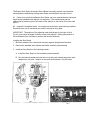
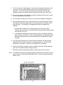
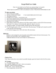
Technical Bulletin
Bulletin No.: PRO-05-01
Effective Date: 5/23/77
Cancels: PRO-05-01 dated 4/6/76
Page: 1 of 3
AUTOMATIC SLACK ADJUSTER INSTALLATION
INFORMATION
Subject:
Every Automatic Slack Adjuster sold through the Aftermarket Division includes
BWS-582 Installation Instructions which contain important information regarding a retrofit
installation. A copy of the instruction sheet was forwarded on Bulletin 05-1 and we
suggest that you retain and carefully review the procedures.
Of particular importance is the statement on page 2 which reads:
IMPORTANT: The position of the adjusting crank and linkage (to the right or left
in Fig. #1) must not be changed in relation to the slack adjuster. Altering the
position of this mechanism (from one side to another) will cause a malfunction.
Also, to insure proper operation, it is recommended that the Bendix Automatic Slack
Adjuster be used in retrofit installations only with chamber sizes of Type 16 or larger.
The Bendix “Sure Stroke” Automatic Slack Adjuster is a device with great sales potential
to the OE specification and retrofit market. However, as with any new device, proper
installation is of prime importance. If you have any questions regarding installation of
the “Sure Stroke”, please contact your Bendix HVSG representative.
The Bendix Sure Stroke Automatic Slack Adjuster can easily replace most standard
slack adjuster installations providing some simple considerations are kept in mind.
#1. Check to be sure that the Bendix Sure Stroke you have selected has the same arm
length as the standard slack adjuster it is replacing. (This measurement can be
determined by measuring from the center of the yoke pin to the center of the cam shaft
spline.)
#2. Inspect the foundation brake. All components should be in good working condition.
Excessive drum out of roundness may result in excessive lining wear.
IMPORTANT: The position of the adjusting crank and linkage (to the right or left in
Fig. #1) must not be changed in relation to the slack adjuster. Altering the position of
this mechanism (from one side to another) will cause malfunction.
Installing the Sure Stroke
1. Block the wheels of the vehicle and manually cage all Spring Brake Actuators.
2. Remove the standard slack adjuster and brake chamber yoke assembly.
3. Install the Sure Stroke in the following manner:
A. Install the Sure Stroke on the foundation brake camshaft.
B. Run the brake chamber push rod lock nut up the push rod and remove the yoke
adapter from the yoke. Install it on the push rod as shown in Fig. #2 below.
C. Turn the external ¾” adjusting hex in the direction indicated by the arrow on the
crank arm, until the brake chamber push rod enters the slack adjuster yoke
assembly. The end of the brake chamber push rod should enter the yoke
assembly and be even with the surface of the throat of the yoke. See Fig. #2.
D. Run the Sure Stroke yoke adapter up the brake chamber push rod until it enters
the yoke assembly fully and tighten.
E. Run the brake chamber push rod lock nut up to the yoke adapter and tighten it.
F. After installing the Sure Stroke, check that the arm of the slack adjuster forms a
90º angle with the brake chamber push rod at approximately mid stroke of the
brake chamber. The following is a suggested procedure to establish this
condition.
1. With the brake chamber in the released position and the Sure Stroke
installed, place a Square (or equivalent object) along the brake chamber push
rod as shown in Fig. #3.
2. If the distance measured is less than shown in Fig. #3, the Brake Chamber
push rod must be shortened. If the measured distance is greater than shown,
the brake chamber push rod must be replaced with an appropriately longer
assembly.
G. Once the proper positioning of the Sure Stroke is obtained, the initial manual
adjustment must be made using the ¾” manual adjuster hex. After the initial
adjustment is complete, no further manual adjustment is necessary.
H. With the “Sure Stoke” installed, check for sufficient clearance. (Brake chamber
push rod in the released and full stroke position.)
I.
Manually uncage the spring brakes before returning the vehicle to service.
Note: For additional information regarding operation, maintenance and testing, obtain a
copy of Instruction and Service Data Sheet SD-83, from the nearest authorized
Bendix outlet.