1
LEAKAGE TEST
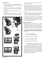
1. Park the vehicle on a level surface and block or chock
the wheels. Release the parking brakes and build the
air system to full pressure.
2. Turn the engine OFF and make 4 or 5 brake applications
and note that the service brakes apply and release
promptly.
3 1 2
3. Build system pressure to governor cut-out
and turn the
engine OFF.
1
2
3
4. After determining the pressure loss with the brakes
released (2 psi/minute allowed), make and hold a
5. Begin timing pressure loss for two minutes while
watching the dash gauges for a pressure drop. The
leakage rate for the service reservoirs should not exceed four (4) psi within two minutes for a single vehicle,
six (6) psi. within two minutes for a tractor/trailer, and
eight (8) psi within two minutes for a tractor with two
trailers.
6. If either circuit exceeds the leakage values above, apply
soap solution to the exhaust port of the modulators and
any other components in the respective circuit.
7. The leakage at the exhaust port of most Bendix
components, including M-40™ modulators, should not
exceed a one-inch bubble in three seconds. If leakage
at the modulator is determined to exceed the maximum
limits, replace the modulator.
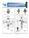
Bendix M-40HF
Modulator
®
full service brake application. Allow the pressure to
stabilize for one minute.
™
ELECTRICAL TESTS
1. Before testing the solenoid assembly of a suspect
modulator, its location on the vehicle should be
confirmed using the troubleshooting procedure for the
specific antilock controller in use. (See the Service Data
Sheet available on www.bendix.com document library.)
Twist-Lock
Connector
(Bayonet
Connector)
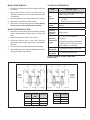
2. Proceed to the modulator in question and inspect its
wiring connector. Disconnect the connector and test the
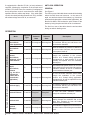
resistance between the pins on the modulator. Refer
to Figure 7.
Optional Adapter
HOLD to SOURCE (41-42):
A.
Bendix® M-40QR™
Modulator
12V systems: Read 4.8 to 5.6 Ohms.
2
1
Bayonet
Terminal Function
Name
1
Exhaust
2
Source
3
Hold
3
1
2
3
2
EXHAUST ro SOURCE (41-43):
12V systems: Read 4.8 to 5.6 Ohms.
24V systems: Read 13.9 to 16.3 Ohms.
C. Individually test the resistance of each pin to
vehicle ground and note there is NO continuity.
41
3
1
2
1
B.
3
Twist-Lock Connector
(Bayonet Connector)
Packard
Terminal Function
Name
41
Source
42
Hold
43
Exhaust
24V systems: Read 13.9 to 16.3 Ohms.
1
2
3
42
43
Packard Electric Connector
(280 Series)
FIGURE 7 - EXTERIOR VIEWS AND ELECTRICAL
CONNECTIONS
6
If the resistance readings are as shown, the wire
harness leading to the modulator may require repair or
replacement. Before attempting repair or replacement
of the wire harness, refer to the test procedures
specified for the antilock controller in use for possible
further testing that may be required to substantiate the
wire harness problem. If the resistance values are not
as stated, replace the modulator.