1
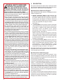
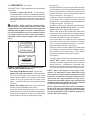
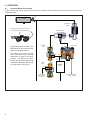
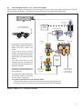
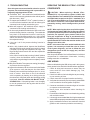
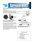
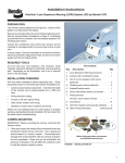
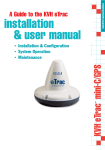
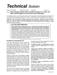
SD-13-21021
Bendix® eTrac™ Automated Air Pressure Transfer System
Drive axle
Steer axle
Wheel speed sensors
(All wheel-ends)
Air supply
Tag axle
Drive axle
suspension
air bags
(2)
Tag axle
suspension
air bags
(2)
See below for labeled
component descriptions
D
4
Bendix®
brand ABS
controller
S
E
C
SUP
EXH
1
2
S
D
D
DEL
S
D
(Premium or
Advanced)
D
5
Leveling
valve
D
3
When needed, the
system provides
the ability to add air
pressure to the drive
axle suspension air
bags, and remove
air pressure from the
tag axle suspension
air bags
6
Bendix® R-12®
relay valve
Bendix® brand ABS controller
(Premium or Advanced EC-60 designation or later)
1
D
Bendix® DC‑4®
double-check
valve
6
4
Two Bendix® RV-3™
valves
2
Bendix® FCS‑9700™
solenoid valve
5
Example of a
Simple 6x2
Air Suspension
Leveling
Control System
Leveling
valve
S
SUP
EXH
3
DEL
D
The air pressure is distributed equally to the
drive and tag axle suspension air bags
FIGURE 1 - BENDIX® eTrac™ SYSTEM WITH SYSTEM COMPONENTS AND A SIMPLE LEVELING SYSTEM SCHEMATIC
1.INTRODUCTION
The Bendix ® eTrac™ automated air pressure transfer
system is used on 6 x 2 semi-tractors that feature Bendix®
premium and advanced Antilock Brake Systems (ABS).
This system complements the Bendix ® Smart ATC ™
(
Automatic Traction Control) feature of our ABS system to
provide improved traction at low speeds (e.g. pulling away
on an inclined ramp, or in slippery conditions such as mud
or snow-covered surfaces, etc.)
When active, the Bendix eTrac system vents — or
“dumps” — the air pressure of the tag axle suspension
air bags, and increases the air pressure in the drive axle
suspension air bags to a pre-determined maximum. This
action helps the drive axle to gain more traction.
1
GENERAL SAFETY GUIDELINES
WARNING! PLEASE READ AND
FOLLOW THESE INSTRUCTIONS
TO AVOID PERSONAL INJURY OR DEATH:
When working on or around a vehicle, the following
guidelines should be observed AT ALL TIMES:
▲ Park the vehicle on a level surface, apply the parking
brakes and always block the wheels. Always wear
personal protection equipment.
▲ Stop the engine and remove the ignition key when
working under or around the vehicle. When working
in the engine compartment, the engine should be shut
off and the ignition key should be removed. Where
circumstances require that the engine be in operation,
EXTREME CAUTION should be used to prevent personal
injury resulting from contact with moving, rotating,
leaking, heated or electrically-charged components.
▲ Do not attempt to install, remove, disassemble or
assemble a component until you have read, and
thoroughly understand, the recommended procedures.
Use only the proper tools and observe all precautions
pertaining to use of those tools.
▲ If the work is being performed on the vehicle’s air brake
system, or any auxiliary pressurized air systems, make
certain to drain the air pressure from all reservoirs
before beginning ANY work on the vehicle. If the vehicle
is equipped with a Bendix® AD-IS® air dryer system, a
Bendix® DRM™ dryer reservoir module, or a Bendix®
AD-9si™ air dryer, be sure to drain the purge reservoir.
▲ Following the vehicle manufacturer’s recommended
procedures, deactivate the electrical system in a manner
that safely removes all electrical power from the vehicle.
▲ Never exceed manufacturer’s recommended pressures.
▲ Never connect or disconnect a hose or line containing
pressure; it may whip. Never remove a component or
plug unless you are certain all system pressure has
been depleted.
▲ Use only genuine Bendix® brand replacement parts,
components and kits. Replacement hardware, tubing,
hose, fittings, etc. must be of equivalent size, type
and strength as original equipment and be designed
specifically for such applications and systems.
▲ Components with stripped threads or damaged parts
should be replaced rather than repaired. Do not
attempt repairs requiring machining or welding unless
specifically stated and approved by the vehicle and
component manufacturer.
▲ Prior to returning the vehicle to service, make certain all
components and systems are restored to their proper
operating condition.
▲ For vehicles with Automatic Traction Control (ATC),
the ATC function must be disabled (ATC indicator
lamp should be ON) prior to performing any vehicle
maintenance where one or more wheels on a drive axle
are lifted off the ground and moving.
▲ The power MUST be temporarily disconnected
from the radar sensor whenever any tests USING A
DYNAMOMETER are conducted on a Bendix® Wingman®
Advanced™-equipped vehicle.
▲ You should consult the vehicle manufacturer's
operating and service manuals, and any related
literature, in conjunction with the Guidelines above.
2
2.DESCRIPTION
The system features two states (with or without the Mud/
Snow switch engaged) and three modes (Normal/inactive;
System Active, and Pressure-Limiting Modes):
Mud/Snow Dash Switch Not Engaged
When the Mud/Snow dash switch is not engaged, the three
modes of operation are:
● Normal (“automatic”) Mode is ready whenever the
vehicle is moving at less than 25 MPH. In this mode
the system behaves just like a typical air suspension
leveling system that adjusts for different loads by a
mechanical leveling (height control) valve that adjusts
all four rear suspension air bags as needed.
See Figure 3.
● The Active Mode occurs when the vehicle encounters
road conditions where automatic traction control (ATC)
is activated. In addition to the actions of the Bendix®
Smart ATC system, the Bendix ® eTrac ™ system
automatically vents (“dumps”) air pressure from the
tag axle air bags. See Figure 4.
With the drop in air pressure in the tag axle, the leveling
valve normal function adds air pressure to the drive axle
suspension air bags. When the air pressure reaches
a pre-determined maximum, the system enters the
Pressure Limiting Mode.
● The Pressure-Limiting Mode prevents system air
pressure delivery to the drive axle suspension air bags
above a pre-determined maximum pressure. The
system will then — using the backfeed valve — permit
the leveling valve to add air back into the tag axle
suspension air bags as needed. See Figure 5.
Automatic activations are terminated five (5) seconds after
the end of an ATC event, and are not able to be initiated at
vehicle speeds above 25 MPH.
Mud/Snow Dash Switch Engaged
This mode is sometimes called “semi-automatic” since
the driver engages the Bendix eTrac system, however the
system automatically terminates five (5) seconds after the
vehicle reaches ten (10) MPH.
By activating the Mud/Snow dash switch, the driver can be
proactive in anticipating slippery conditions. For example,
a driver — moving at five (5) MPH approaching a section of
road that is coated with mud — may anticipate this problem
zone and press the Mud/Snow switch. The Bendix eTrac
system will immediately enter the Active Mode described
above. When the drive axle reaches the pre‑determined
maximum pressure, the Pressure-Limiting Mode (described
above) will be entered.
[It is useful to note that other systems where the driver is
responsible for remembering to disengage the air transfer
(typically by using a dash button) can lead to significant
damage to the driveline if left active.]
3. COMPONENTS See Figure 1.
See Figure 3.
The Bendix® eTrac™ system installation uses the following
components:
• Electronic Control Unit (ECU): The specificallyconfigured Bendix® Premium, or Advanced, ABS ECU
monitors the speed sensor signals at each wheel-end
and during automatic traction control events under 25
MPH signals the Bendix® FCS-9700™ Solenoid Valve
to close.
CAUTION: When replacing a Bendix eTracenabled ECU, it is important to replace it ONLY with
another Bendix eTrac-enabled ECU as indicated by the
CAUTION label located on the ECU. Installation of a
non-eTrac-enabled ECU on an eTrac-equipped vehicle
can result in erroneous eTrac system interventions,
potentially causing vehicle damage and/or personal
injury.
During the Bendix eTrac system Active Mode, the relay
valve isolates the rest of the air suspension system from
the tag axle suspension air bags and “dumps” the air
pressure from them. The air is exhausted through the
relay’s exhaust port. See Figure 4.
During the Pressure-Limiting Mode, the control port
of the “dump” valve receives air pressure from the
backfeed valve. This re-inflates the tag axle suspension
air bags as required. See Figure 5.
• Bendix® DC-4® Double-Check Valve: This valve
toggles based on the higher supply pressure.
When in Normal Mode the double-check valve allows
the delivery from the solenoid valve to hold the tag axle
suspension air bags open to the same pressure as the
drive axle suspension air bags. See Figure 3.
In the Active Mode, the control air from the solenoid
valve to the “dump” valve ends, and the air is vented
back — through the double-check valve — and out of
the solenoid valve exhaust. See Figure 4.
During the Pressure-Limiting Mode, the double-check
valve allows air pressure from the backfeed valve to
the control port of the “dump” valve. This re-inflates
the tag axle suspension air bags as required.
See Figure 5.
See SD-03-2202 for more information about this valve.
CAUTION
REPLACE ONLY WITH
ETRAC ENABLED ECU
REFERENCE BW2921
Bendix® eTrac™
CAUTION
REPLACE ONLY WITH ETRAC
ENABLED ECU
REFERENCE SD-13-21021
FIGURE 2 - EITHER BENDIX® eTrac™ SYSTEM CAUTION
LABEL MAY BE LOCATED ON THE ECU
• Dash-Mounted Mud/Snow Switch (Not shown.)
• Bendix FCS-9700 Solenoid Valve: Energized by the
ECU, this normally-open valve moves to the closed
position when the Bendix eTrac system is active (and
remains on five (5) seconds after the traction event
ends). See SD-03-10433 for more information about
this valve.
• Bendix® R-12® Relay Valve: This is the “dump” valve
used for venting the Bendix eTrac system.
During the Normal Mode this relay valve is used to
provide an open channel for the inflation and deflation
of the tag axle suspension air bags (to maintain equal
pressure with the drive axle suspension air bags).
See SD-03-1064 for more information about this valve.
• Bendix® RV-3™ Valves: Typically used for pressure
reduction in air brake systems, this valve provides two
special functions: It operates as a backfeed valve,
and it also operates as a pressure-limiting valve. See
SD-03-3515 for general information about this valve.
NOTE: When replacing the valves used in this
system, it is important to replace ONLY like for like
part numbers (or direct replacement parts as verified
by Bendix.) In particular, the system upper pressure
limit for the drive axle suspension air bags is predetermined by the OEM, and this upper pressure limit
determines the specific Bendix RV‑3 valves that must
be used to avoid damage to the drive train.
NOTE: In the case of the valve used to backfeed the
Bendix eTrac system, it is necessary to install the valve
as shown in the system diagrams, and not to follow
the port designations (such as SUP for supply, etc.)
cast into the valve housings.
3
4.OPERATION
4.1
Automatic Mode: Normal Mode.
Figure 3 shows the normal system position where the leveling valve controls the delivery of air to the rear axle air
suspension bags.
Pressure protection valve
Air supply
D
Solenoid valve
(OPEN)
The leveling valve maintains equal pressure in
the drive and tag axle suspension air bags
Double check valve
EXH
SUP
DEL
EXH
Drive axle
Tag axle
•
The solenoid valve remains in the
OPEN position; this holds the relay
valve in the applied position.
•
The deliver y from the leveling
valve maintains the drive and tag
suspension air bags at the same
pressure. The delivery air travels
through the backfeed and limiting
valves to the drive axle, and through
the relay valve to the tag axle.
Backfeed
valve
“Dump” valve
SER
DEL
SUP
Limiting
valve
SUP
DEL
EXH
DEL
SUP
LEVELING
VALVE
DEL
SUP
Delivery to the
drive axle air bag
suspension
Delivery to the tag axle
air bag suspension
EXH
FIGURE 3 - BENDIX® eTrac™ SYSTEM NORMAL (“AUTOMATIC”) MODE
4
4.2
Automatic Mode: Bendix® eTrac™ System Active Mode.
Figure 4 shows the Bendix eTrac system in its Active Mode where the “dump” valve controls the delivery of air to the
rear axle suspension air bags. This diagram is for both automatic and semi-automatic applications.
Pressure protection valve
Air supply
D
Solenoid valve
(CLOSED)
The air is vented from the tag
axle suspension air bags
Bendix®
brand ABS
controller*
Double check valve
EXH
SUP
DEL
Drive axle
Tag axle
•
An Automatic Traction Control (ATC)
event is detected by the ABS ECU.
Bendix® Smart ATC™ works to aid
traction.
•
If the vehicle speed is below
25 MPH, the solenoid valve will be
energized by the Bendix® ABS ECU
and the valve moves to the CLOSED
position.
•
•
The relay valve moves to the
unapplied position, permitting the
air pressure from the tag axle to be
released (“dumped”).
The delivery from the leveling valve
maintains the drive axle suspension
air bag pressure.
“Dump” valve
Backfeed
valve
SER
DEL
SUP
Limiting
valve
SUP
DEL
DEL
EXH
SUP
LEVELING
VALVE
DEL
SUP
Delivery to the
drive axle air bag
suspension
EXH
•
The Bendix eTrac system intervention
automatically ends five (5) seconds
after the traction event ends.
•
*For vehicles with Bendix® EC‑80™ ATC/ESP ECUs:
When the eTrac system is in the semi-automatic mode, if the parking brake is set,
the ability to vent air pressure from the tag axle with the eTrac feature is disabled.
Air from the tag axle
air bag suspension
is vented through the
“dump” valve exhaust
FIGURE 4 - BENDIX® eTrac™ SYSTEM ACTIVE MODE
5
4.3
Automatic Mode: Bendix® eTrac™ System Active Mode with Pressure-Limiting Mode.
Figure 5 shows the Bendix eTrac system in its Pressure-Limiting Mode.
Pressure protection valve
Air supply
D
Solenoid valve
(CLOSED)
Bendix®
brand ABS
controller
Double check valve
The Bendix eTrac system adds up to a
pre‑determined amount of air pressure to the drive
axle suspension air bags
EXH
EXH
SUP
DEL
Drive Axle
“Dump” valve
Backfeed
valve
Tag Axle
SER
The system allows the leveling
valve to re-inflate the tag axle
suspension air bags as required
DEL
SUP
DEL
DEL
SUP
Limiting
valve
SUP
LEVELING
VALVE
DEL
Delivery to the drive
axle suspension air
bag held
• The Bendix ® Smart ATC™ continues to work
during the traction event.
• The air pressure in the drive axle suspension
air bags is increased up to the pre-determined
pressure limit.
• When the pre-determined pressure limit is
reached, the inner mechanism within the limiting
valve moves and this results in the air bag
pressure in the drive axle suspension air bags
being held at that pressure.
SUP
Air supply delivered
to the tag axle
suspension air bag as
required
EXH
• The inner mechanism of the backfeed valve also
moves at the pressure limit and delivers air to the
“dump” valve piston. The “dump” valve applied
position delivers air pressure to the tag axle
suspension air bags proportional to the pressure
applied to the dump valve piston.
• The Bendix eTrac system intervention (during
which the solenoid valve remains in the CLOSED
position) automatically ends five (5) seconds after
the traction event ends.
FIGURE 5 - BENDIX® eTrac™ SYSTEM PRESSURE-LIMITING MODE
6
EXH
5.TROUBLESHOOTING
Since this system uses some familiar valves for special
purposes, the troubleshooting guide is presented in a
frequently-asked-questions format:
Q:The Bendix® RV-3™ valve used for the backfeed function
seems to be incorrectly plumbed on the vehicle (and in
this document). Why?
A:To support special Bendix® eTrac™ system functions, it
is correct that the backfeed valve has its delivery port
connected to the leveling valve delivery port.
Q:What will happen if the backfeed valve’s supply is
connected to the leveling valve delivery?
A:An incorrectly installed backfeed valve will result in the
pressure-limiting function not working. The technician
may check if the backfeed function is working by
depressing the Mud/Snow switch on a fully loaded
vehicle; the vehicle’s tag axle should not drop down to
the suspension stops.
Q: How can I tell if the pressure-limiting function is
working?
A:With a fully loaded vehicle, depress the Mud/Snow
switch and verify that only a small amount of air is vented
(“dumped”) by the tag axle suspension air bags. The
tag axle bags should remain firm and the suspension
relatively level.
In the case of a vehicle that is running “bobtail” (without
a trailer), when the Mud/Snow switch is depressed,
verify that the tag axle bags become completely vented
(“dumped”).
Q:Why is the Bendix eTrac system not venting (“dumping”)
air pressure from the tag axle?
A:Inspect the exhausts of all the valves used in the Bendix
eTrac system to verify that they are free from debris.
Exhaust ports can develop blockages from ice, snow,
mud, or insects. Also check to see if the solenoid
valve is operating by listening for a clicking noise (as
the solenoid is energized) when the Mud/Snow switch
is activated. Note for vehicles with Bendix® EC‑80™
ATC/ESP ECUs: If the parking brake is set, the ability
to vent air pressure from the tag axle with the eTrac
feature is disabled.
SERVICING THE BENDIX® ETRAC™ SYSTEM
COMPONENTS
CAUTION: When replacing a Bendix eTracenabled ECU, it is important to replace it ONLY with
another Bendix eTrac-enabled ECU as indicated by the
CAUTION label located on the ECU. Installation of a
non-eTrac-enabled ECU on an eTrac-equipped vehicle
can result in erroneous eTrac system interventions,
potentially causing vehicle damage and/or personal
injury.
NOTE: When replacing the valves used in this system,
it is important to replace ONLY like for like part numbers
(or direct replacement parts as verified by Bendix.) In
particular, the system’s upper pressure limit for the
drive axle suspension air bags is pre-determined by
the OEM, and this upper pressure limit determines the
specific Bendix RV‑3 valves that must be used to avoid
damage to the drive train.
NOTE: In the case of the valve used to backfeed in this
system, it is necessary to install the valve as shown
in the system diagrams, and not to follow the port
designations (such as SUP for supply, etc.) cast into
the valve housings.
See the specific Bendix® Service Data Sheet for individual
components for maintenance information, including
leakage tests after re-installation.
ABS WIRING
When troubleshooting the ABS wiring used in this system,
some general rules should be followed where applicable.
1. Check all wiring and connectors to ensure they are
secure and free from visible damage (e.g. cuts,
abrasions, etc.).
2. Check for evidence of wire chafing due to poor routing,
or poor securing of wires.
3. Check connectors for proper insertion and locking.
4. Verify that the connector pins are properly greased with
a non-conductive electrical grease compound.
5. Connector terminals must not show signs of corrosion
or exposure to the environment.
6. Never pierce wire insulation when checking for
continuity.
7. Do not deform individual pins or sockets during probing
with a volt/ohm meter.
8. It is strongly recommended that all wiring harnesses and
sensor leads are properly secured at least every 18 inches.
9. Apply a moderate amount of non-conductive electrical
grease to each connector pin before reconnecting.
7
www.bendix.com
For the latest information, and for free downloads of literature
and the Bendix® ACom® diagnostics software, and its User
Guide, visit the Bendix website at www.bendix.com.
Bendix Technical Assistance Team
For technical support, call the Bendix technical assistance
team at 1-800-AIR-BRAKE (1‑800‑247-2725), Monday
through Friday, 8:00 a.m. to 6:00 p.m. ET.
Alternatively, you may e-mail the Bendix Tech Team at:
[email protected].
To better serve you, please record the following
information before you call the Bendix Tech Team, or
include this information in your e-mail:
• Bendix product model number, part number and
configuration.
• Vehicle make and model.
• Vehicle configuration. (Number of axles, tire size, etc.)
•
System performance symptoms: When do they occur?
• What DTCs have been identified using LEDs, blink
codes or diagnostic tools?
• What troubleshooting/measurements have been
performed?
• What Bendix service data literature do you have or
need?
Log-on and Learn from the Best
On-line training that's available when you are
Visit www.brake-school.com.
24/7/365.
SD-13-21021 © 2014 Bendix Commercial Vehicle Systems LLC, a member of the Knorr-Bremse Group • All Rights Reserved • 11/14
8