1
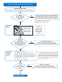
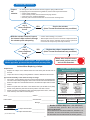
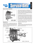
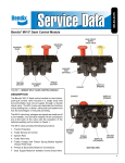
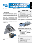
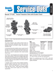
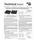
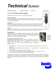
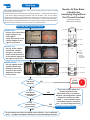
Start Here
All foundation brakes are designed to convert kinetic energy (energy of motion) into heat
and work (to stop the vehicle).
Air disc brakes work the same way and in everyday operation — compared to drum brakes
— will produce higher braking temperatures and cool off faster. Also, air disc brakes
will often have differences in temperatures at wheel ends on the same axle. The actual
temperatures reached will depend on the vehicle configuration, vocation and brake usage.
This document is intended to help technicians identify instances where an individual wheel
end has evidence of thermal overload, and check for potential causes.
Bendix Air Disc Brake
Checklist for
Identifying Single Wheel
End Thermal Overload
®
Follow all General Safety
Guidelines (see final page.)
SECTION ONE: Inspect the Vehicle
c L. Steer
Question One:
Do any of the rotors have
bright orange or red
color edges?
Check the box(es) on the
vehicle diagram to the
right for any found.
c L. Drive
Normal
Steer Axle
Drive
Axle
Question Three:
Are any tappets and/or
guide pin boots heat
damaged? Check the
box(es) on the vehicle
diagram to the right
for any found.
c R. Drive
Evidence of thermal overload
c L. Add’l.
Question Two:
Are any of the calipers
coated with a bright
orange or red colored
dust? Check the box(es)
on the vehicle diagram to
the right for any found.
c R. Steer
c R. Add’l.
Additional
Axle
Normal
Check
box(es)
where
Thermal
Overload is
suspected.
Evidence of thermal overload
c L. Trlr. Front
c L. Trlr. Rear
Typical
Evidence of thermal
overload
Are
any boxes
checked?
Trailer Front
Axle
Trailer Rear
Axle
c R. Trlr. Front
c R. Trlr. Rear
Evidence of thermal
overload
STOP!
Exit this
flowchart.
NO
YES
Are
both boxes
on a single axle
checked?
YES
NO
Only
one box has a
check mark?
YES
This is not a single wheel end
Thermal Overload event.
When both ends of an axle are
affected, a thorough brake system
diagnosis is needed, as other
factors — such as brake balance,
overloaded vehicles, or extreme
use — are more likely the source.
Go to Section Two (over)
NO
In cases where more than one wheel end is affected — but on different
axles — complete a separate checklist for each brake being examined.
SECTION TWO: Investigate Other Potential External Causes
• Follow all Safe Maintenance Practices (see final page.)
Inspect the brake pads.
(New pads have 21 mm of brake pad, plus a 9 mm backing plate.)
Is
there
2 mm, or less, of
brake pad friction
material?*
YES
*2 mm of friction material, plus a 9 mm
backing plate, for a total of 11 mm.
NO
Inspect the
caliper
Replace the pads (axle set recommended)
after performing all Section Two inspections.
(Not a Thermal Overload warranty condition.)
Push/pull
by hand to check the
caliper movement
[at least 0.75 Inch
(20 mm) with the
pads removed]
Does
the brake
caliper have
restricted movement in
the inboard/outboard
direction?
YES
Complete this
step on level
ground, with the
wheels chocked
and the parking
brake temporarily
released!
Service the guide pins.
Perform all Section Two inspections.
(Not a Thermal Overload warranty condition.)
NO
Inspect the
air hoses
(“jounce
lines”).
• Is air trapped in the hose?**
• Do the hose(s) pull or push on the caliper? (It is
important that the hoses permit the lateral motion of
the caliper, the vertical motion of the suspension, and
— for steering axles — the full turn of the wheels.)
• Are there any kinks, restrictions?
**Take full safety precautions during the inspection
for trapped air, to avoid the air hose whipping if air
pressure is found to be trapped. Conditions that
might cause trapped air include kinked lines, or
when an ABS modulator is malfunctioning and
not exhausting service air.
• Are the hoses in good condition?
Are
any of
these conditions
found?
Service as needed.
Perform all Section Two inspections.
(Not a Thermal Overload warranty condition.)
YES
NO
Go to the next page . . .
2
SECTION TWO Continued
Inspect
the
actuator.
On level ground, with the wheels chocked, cage the spring brake actuator
(if equipped) per the manufacturer’s guidelines, remove and inspect the actuator.
• Is there visible damage?
• In the installed position, was the lowest drain plug sealed?
• Is the seal in poor condition/damaged?
• Does the push-rod extend further than 15 mm from the mounting face?
Are
any of
these conditions
found?
YES
Service the actuator.
(Not a Thermal Overload warranty condition.)
NO
With the actuator removed, inspect
the internal caliper surfaces through
the actuator push rod opening.
Are
any of
these conditions
found?
• Is there visible damage, rust, water?
• With the pads removed, use a screw driver to depress the lever.
Does the lever have a restricted range of motion? (The lever
must touch the caliper body when fully retracted.)
YES
Replace the caliper. Inspect the rotor.
(Not a Thermal Overload warranty condition.)
NO
No Section Two external causes found? Replace the caliper.
Where applicable, process a thermal overload warranty claim.
Actions When Replacing a Caliper
Replacement:
c
Replace the caliper on the affected wheel end and all the pads at both ends of
the axle.
c
Inspect the rotor according to the guidelines in Service Data sheet SD‑23‑7541.
If the brake assembly is still under warranty coverage:
c
File a claim. Clearly state the claim is for a single axle thermally overloaded brake.
The claim must include photographs of the rotor from both ends of the affected axle.
c
Return the caliper from the affected wheel end, and label the caliper with the claim
number.
c
Return the pads from both sides of the affected axle (LH and RH set of pads).
Please clearly label the parts with the wheel position and claim number.
c
Please include this completed checklist, the photographs of the rotors, and a copy
of the warranty claim with the returned parts.
VIN #: __________________________________ Claim #: ________________________
Vehicle Make: ____________________________ Vehicle Model: ___________________
Mileage: ____________________
Where other external causes
were found, perform service
and exit this flowchart.
Bendix® ADB22X® Air Disc Brake
Replacement Part Numbers
Caliper/Carrier
Axial Bolt
12 degree
Right Fixed Pin
K081142
Left Fixed Pin
K081143
Vertical Bolt
12 degree
Right Fixed Pin
K081256
Left Fixed Pin
K081257
Left Fixed Pin
Right Fixed Pin
Please note that replacement caliper/carrier bolts (available
from the vehicle manufacturer) are recommended.
Caliper Only
12 degree
Right Fixed Pin
K081258
Left Fixed Pin
K081259
Bendix TechTeam Help Line: 1‑800‑AIR‑BRAKE,
<Part Number>
<Serial Number>
Caliper Part Number: _________________
Caliper Serial Number: _________________
(Air Disc Brake Label)
3
(1‑800‑247‑2725), option 2-1. Mon. - Fri., 8 a.m. - 6 p.m.
Reference Document:
Service Data: SD‑23‑7541 Bendix® ADB 22X™, ADB 22X‑V™ Air
Disc Brakes. Go to the document library at www.bendix.com for
free downloads of Service Data Sheets and warranty policies.
GENERAL SAFETY GUIDELINES
WARNING: Not all wheels and valve stems are
compatible with Bendix Air Disc Brakes. Use only wheels and
valve stems approved by the vehicle manufacturer to avoid
the risk of valve stem shear and other compatibility issues.
WARNING! PLEASE READ AND
FOLLOW THESE INSTRUCTIONS
TO AVOID PERSONAL INJURY OR DEATH:
When working on or around a vehicle, the following
guidelines should be observed AT ALL TIMES:
WARNING: AVOID CREATING DUST.
POSSIBLE CANCER AND LUNG DISEASE
HAZARD.
▲ Park the vehicle on a level surface, apply the parking
brakes and always block the wheels. Always wear
personal protection equipment.
▲ Stop the engine and remove the ignition key when
working under or around the vehicle. When working
in the engine compartment, the engine should be shut
off and the ignition key should be removed. Where
circumstances require that the engine be in operation,
EXTREME CAUTION should be used to prevent personal
injury resulting from contact with moving, rotating,
leaking, heated or electrically-charged components.
▲ Do not attempt to install, remove, disassemble or
assemble a component until you have read, and
thoroughly understand, the recommended procedures.
Use only the proper tools and observe all precautions
pertaining to use of those tools.
▲ If the work is being performed on the vehicle’s air brake
system, or any auxiliary pressurized air systems, make
certain to drain the air pressure from all reservoirs
before beginning ANY work on the vehicle. If the vehicle
is equipped with a Bendix® AD-IS® air dryer system, a
Bendix® DRM™ dryer reservoir module, or a Bendix®
AD-9si™ air dryer, be sure to drain the purge reservoir.
▲ Following the vehicle manufacturer’s recommended
procedures, deactivate the electrical system in a manner
that safely removes all electrical power from the vehicle.
▲ Never exceed manufacturer’s recommended pressures.
▲ Never connect or disconnect a hose or line containing
pressure; it may whip. Never remove a component or
plug unless you are certain all system pressure has
been depleted.
▲ Use only genuine Bendix® brand replacement parts,
components and kits. Replacement hardware, tubing,
hose, fittings, etc. must be of equivalent size, type
and strength as original equipment and be designed
specifically for such applications and systems.
▲ Components with stripped threads or damaged parts
should be replaced rather than repaired. Do not
attempt repairs requiring machining or welding unless
specifically stated and approved by the vehicle and
component manufacturer.
▲ Prior to returning the vehicle to service, make certain all
components and systems are restored to their proper
operating condition.
▲ For vehicles with Automatic Traction Control (ATC),
the ATC function must be disabled (ATC indicator
lamp should be ON) prior to performing any vehicle
maintenance where one or more wheels on a drive axle
are lifted off the ground and moving.
▲ The power MUST be temporarily disconnected
from the radar sensor whenever any tests USING A
DYNAMOMETER are conducted on a Bendix® Wingman®
Advanced™-equipped vehicle.
▲ You should consult the vehicle manufacturer's
operating and service manuals, and any related
literature, in conjunction with the Guidelines above.
While Bendix Spicer Foundation Brake LLC does not offer
asbestos brake linings, the long-term affects of some nonasbestos fibers have not been determined. Current OSHA
Regulations cover exposure levels to some components of
non-asbestos linings, but not all. The following precautions
must be used when handling these materials.
• Avoid creating dust. Compressed air or dry brushing must
never be used for cleaning brake assemblies or the work
area.
• Bendix recommends that workers doing brake work must
take steps to minimize exposure to airborne brake lining
particles. Proper procedures to reduce exposure include
working in a well-ventilated area, segregation of areas where
brake work is done, use of local filtered ventilation systems
or use of enclosed cells with filtered vacuums. Respirators
approved by the Mine Safety and Health Administration
(MSHA) or National Institute for Occupational Safety and
Health (NIOSH) should be worn at all times during brake
servicing.
• Workers must wash before eating, drinking or smoking;
shower after working, and should not wear work clothes
home. Work clothes should be vacuumed and laundered
separately without shaking.
• OSHA Regulations regarding testing, disposal of waste and
methods of reducing exposure for asbestos are set forth in
29 Code of Federal Regulations §1910.001. These Regulations provide valuable information which can be utilized to
reduce exposure to airborne particles.
• Material Safety Data Sheets on this product, as required by
OSHA, are available from Bendix. Call 1‑800‑247‑2725 and
speak to the Tech Team or e‑mail [email protected]
BW7514 © 2013 Bendix Commercial Vehicle Systems LLC, a member of the Knorr-Bremse Group. 12/13. All Rights Reserved. Printed in USA.
4