1
3. Place the o-ring seal in the groove around the rear end
cover or in the crankcase proper in the event a rear main
ball bearing is in use. If the rear end cover contains a
precision sleeve bearing that serves as the crankshaft
main bearing, make certain to install the thrust bearing.
Install the end cover in the position as marked before
disassembly, taking care not to damage the sleeve
bearing, if so equipped.
4. Install the four cap screws or nuts that secure the rear
end cover to the crankcase and torque to 175-225 pound
inches.
PISTON & CONNECTING ROD ASSEMBLY
1. Prelubricate the piston, piston rings, wrist pin and
connecting rod.
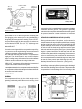
2. Install the piston rings in the correct location with the
ring pipmarks up. (Refer to Figure 11) Stagger the position
of the ring gaps.
3. Align the wrist pin bore of the connecting rod with the
piston bores and install the wrist pin to secure the rod to
the piston. Make certain the TEFLON “buttons” are
installed in each end of the wrist pin.
4. Using an automotive type ring compressor or similar tool,
compress the piston rings and gently install the
connecting rod and piston in the cylinder bore. Install
the connecting rod cap on the connecting rod in the
same position as marked during disassembly.
5. Secure the rod cap to the rod using the two cap screws
and special lockwashers. Torque the cap screw to
between 120-140 pound inches and bend the tabs of the
lockwashers until they are firmly against the flats of the
hex head of the cap screws.
BASE PLATE OR BASE ADAPTER ASSEMBLY
1. Position the base plate or base adapter gasket on the
crankcase and install the base plate or base adapter as
marked before disassembly.
2. Install the cap screws that secure either the crankcase
base plate or crankcase mounting base adapter. Torque
the cap screws evenly to the appropriate valve:
Base plate 85-115 pound inch mounting base adapter 175225 pound inches.
FINAL COMPRESSOR ASSEMBLY
1. Place the cylinder head gasket on the crankcase and
position the head on the crankcase as marked during
disassembly. A gasket sealer is neither required or
recommended.
2. Secure the cylinder head to the crankcase using the
four cylinder head cap screws. Torque the cap screws
in a “X” pattern to between 175-225 pound inches.
3. Using a thread sealant install all necessary pipe plugs
and torque as follows:
1/8" P.T. plugs - 85-105 pound inches
1/2” P.T. plugs - 200-270 pound inches
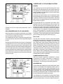
4. Install all crankshaft keys making certain to support the
crankshaft to avoid bearing damage. Install the crankshaft
nut where applicable. When installing drive couplings,
gears or pulleys, DO NOT EXCEED 120 foot pounds
torque on the crankshaft nut. The self locking crankshaft
nut used on the BX-2150™ compressor requires that it
be installed so that the narrow castellation slots are
toward the end of the crankshaft and not against the
pulley, coupling or gear that the nut retains.
Some BX-2150™ through drive compressors require the
installation of a spline coupling on the rear of the
crankshaft. The cap screw securing the coupling should
be torqued to 175-225 inch pounds.
5. Using covers, plugs, or masking tape to protect all ports
if compressor is not to be installed immediately. Protect
the ends of the crankshaft against damage by wrapping
with masking tape or friction tape. The open bottom of a
vertical engine lubricated compressors should be
protected against the entrance of dirt during handling or
storage, by installing a temporary cover over the base.
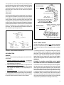
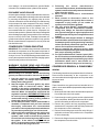
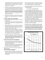
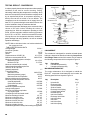
COMPRESSOR BUILD-UP TIME CHART
400
BUILD-UP TIME (SECONDS)
and ball bearing into place. Carefully press the crankshaft
and ball bearing into the crankcase using an arbor press.
Make certain not to damage the oil seal, if the
compressor is so equipped.
COMPRESSOR BUILD-UP TIME
0-120 PSI
6900 CUBIC INCH RESERVOIR
300
200
100
0
1200
1500
1800
2100
2400
2700
COMPRESSOR SPEED (RPM)
3000
13