1
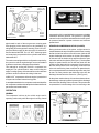
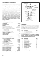
1/2” P.T.
WATER
PORT (3)
OUTLET WATER
ONLY
PART NUMBER
1/2” P.T. AIR
DISCHARGE
(2)
SERIAL NUMBER
TYPICAL NAMEPLATE
1/8” P.T.
GOVERNOR
PORT 2 PLACES
AIR INLET
1/2” P.T.
WATER
PORT
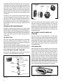
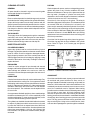
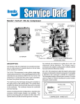
BX-2150™ COMPRESSOR CYLINDER HEAD
pipe threads in each of the two governor mounting pads
allow plugging of the unused port or the installation of a
tubing fitting for remote governor mounting. Three 1/2” N.P.T.
ports provide the means for the connection of coolant lines
and are labeled WATER. Two 1/2” N.P.T. discharge ports
are located on the top and side of the cylinder head and are
labeled AIR OUT.
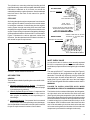
The various mounting and drive configurations required by
the numerous vehicle engine designs are accommodated
by different crankcase castings and crankshafts.
Two methods for cooling the BX-2150™ compressor are
employed. The cylinder head is water cooled using the
engine’s cooling system, while external fins on the crankcase
provide a means for efficient air cooling in that area.
All BX-2150™ compressors utilize the engine’s pressurized
oil system to lubricate internal moving parts.
A nameplate attached to the compressor crankcase identifies
the compressor model and is stamped to indicate the Bendix
part number and serial number.
compression of air is controlled by the compressor unloading
mechanism and the governor. The governor is generally
mounted on the compressor and maintains the brake system
air pressure between a preset maximum and minimum
pressure level.
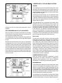
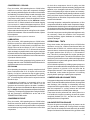
INTAKE AND COMPRESSION OF AIR (LOADED)
During the down stroke of the piston, a slight vacuum is
created between the top of the piston and the head, causing
the flat circular inlet valve to move off its seat. (Note the flat
square discharge valve remains on its seat.) Atmospheric
air is drawn into the intake cavity and flows past the open
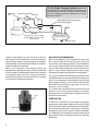
inlet valve and into the cylinder (See Figure 1). As the piston
begins its upward stroke, the air that was drawn into the
cylinder on the down strike is compressed . Air pressure on
the inlet valve plus the force of its spring, returns the inlet
valve to its seat. As the piston continues its upward stroke,
air is compressed and forces the discharge valve away from
its seat. Air flows past the open discharge valve into the
discharge line and on to the reservoirs. (See Figure 2)
As the piston reaches the top of its stroke and starts down,
the discharge valve spring and air pressure in the discharge
line returns the discharge valve to its seat. This prevents the
compressed air in the discharge line from returning to the
OPERATION
GENERAL
The compressor is driven by the vehicle engine and is
operating continuously while the engine is running. Actual
VALVE
STOP
UNLOADER
PISTON
TO
RESERVOIR
INTAKE
INLET
VALVE
VIEW
DISCHARGE
VALVE
PISTON
INTAKE CYCLE
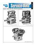
COMPRESSOR MOUNTING/DRIVE CONFIGURATIONS
2
FIGURE 1