1
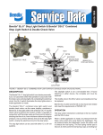
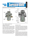
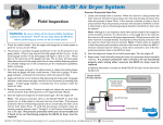
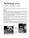
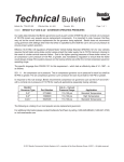
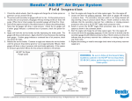
SD-03-10433
Bendix® FCS-9700™ Fan Clutch Solenoid
SUPPLY PORT
MOUNTING
BRACKET
(LEFT HAND)
MOUNTING
BRACKET
(LEFT HAND)
SUPPLY PORT
DELIVERY
PORT
NORMALLY CLOSED
(NC) SOLENOID
NORMALLY OPEN (NO)
SOLENOID
EXHAUST
PORT
ELECTRICAL
CONNECTOR
EXHAUST
PORT
DELIVERY
PORT
ELECTRICAL
CONNECTOR
FIGURE 1 - BENDIX® FCS-9700™ FAN CLUTCH SOLENOID VALVES
DESCRIPTION
The Bendix® FCS-9700™ fan clutch solenoid, shown in
Figure 1, is a low air flow solenoid used to control the fan
clutch. A thermostat controls the solenoid operation.
The fan clutch solenoid is always mounted as a stand
alone solenoid. Depending on the application, it can be a
normally closed (NC) or normally open solenoid (NO). The
integral mounting bracket comes in a right or left position
and is not removable.
OPERATION
Because this solenoid valve is used for an auxiliary air
function, a pressure protection valve, such as a Bendix®
PR-3™ valve, must be installed to protect the air brake
system. Based on the application, the solenoid will
deliver or exhaust air. See Figure 2 for a typical system
configuration.
PREVENTIVE MAINTENANCE
Important: Review the Bendix Warranty Policy before
performing any intrusive maintenance procedures. The
warranty may be voided if intrusive maintenance is
performed during the warranty period.
No two vehicles operate under identical conditions; as
a result, maintenance intervals may vary. Experience is
a valuable guide in determining the best maintenance
interval for air brake system components. At a minimum,
the solenoid should be inspected every 6 months or
1500 operating hours, whichever comes first, for proper
operation. Should the solenoid not meet the elements
of the operational tests noted in this document, further
investigation and service of the valve may be required.
SERVICE CHECKS
When the in-cab switch is pressed to activate or deactivate
the fan clutch, the Bendix FCS-9700 solenoid will promptly
exhaust (NO) or apply (NC). Note that the solenoid part
number label is marked with an NO or NC for identification.
Continuous exhausting of air pressure should not occur.
LEAKAGE CHECKS
With the air system fully charged, coat the exhaust ports
of the solenoid with a soap solution. A 1-inch bubble in
three (3) seconds is permitted (175 SCCM).
1
BENDIX FCS-9700 FAN
CLUTCH SOLENOID
®
™
PRESSURE
PROTECTION
VALVE
SUPPLY
RESERVOIR
FAN CLUTCH
THERMOSTAT
CONTROL SWITCH
FIGURE 2 - TYPICAL SYSTEM CONFIGURATION
If the solenoid does not function as described above, or if
leakage is excessive, it is recommended that it be replaced
with a genuine Bendix® service replacement.
REMOVAL
1. Prior to removing the solenoid, apply the parking brakes
and drain all the vehicle reservoirs. Refer to the General
Safety Guidelines in this manual before performing any
service.
2. Identify, and mark, and disconnect the air lines to the
solenoid. Push-to-connect fittings require the collar to
be pressed toward the valve body before the nylon line
can be pulled.
DISASSEMBLY
The Bendix® FCS-9700™ solenoid can not be serviced or
repaired, it can only be replaced with service replacement
solenoids.
INSTALLATION
1. Install the valve on the vehicle by tightening the
mounting bolt to 150-200 inch pounds.
2. Reconnect the air lines and electrical connectors.
3. Charge the reservoirs, then check for operation and
leakage.
3. Identify, mark, and disconnect the electrical connector
from the solenoid.
4. Remove the mounting bolt and remove the solenoid
from the vehicle.
2
BW2902 © 2012 Bendix Commercial Vehicle Systems LLC, a member of the Knorr-Bremse Group • All Rights Reserved • 09/12