1
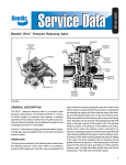
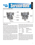
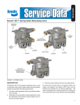
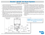
SD-03-3515
®
Bendix® RV-3™ Pressure Reducing Valve
SUPPLY
CAP NUT
SUPPLY
PORT
SUPPLY CAP
NUT O-RING
VALVE STOP
INLET VALVE SPRING
DELIVERY
PORT
INLET/EXHAUST
VALVE
VALVE BODY
SHIMS
PISTON O-RING
MOUNTING
HOLES
PISTON
PLUGGED
PORT
OUTER AND/OR
INNER SPRING
EXHAUST NUT
EXHAUST
DIAPHRAGM
RETAINER
FIGURE 1 - BENDIX® RV-3™ INVERSION VALVE
GENERAL DESCRIPTION
MOUNTING LOCATION
The Bendix® RV-3™ pressure reducing valve is a normallyopen pressure control device. The function of the RV-3
valve is to reduce system air pressure and maintain a
constant specified pre-set pressure below that of system
pressure. Various pressure settings can be obtained
through the use of springs and shims in combination.
Care should be given to assure proper mounting location.
The valve should be mounted with the exhaust pointed
downward (toward the road surface), and mounted high
on the frame rail. It should be away from road spray and
debris. Unprotected or exposed exhaust ports can allow
migration of road contaminants into the valve, which may
cause accelerated wear or unintended operation.
The Bendix RV-3 valve has one supply port and one
delivery port. A single pipe plug is installed in the control
port and should remain in place for most applications of
the RV-3 valve. A rubber exhaust diaphragm is installed
in the end of the valve opposite the supply port. Two .28”
(7.1mm) mounting holes are cast into the valve body.
OPERATION
The spring force exerted on the piston determines the
delivery pressure of the valve. With no air pressure present
at the supply port, the inlet valve is unseated and open while
the exhaust passage through the center of the piston is
sealed by the exhaust valve. Compressed air entering the
supply port flows out the delivery port. Air simultaneously
flows between the piston stem and valve body to the
1
underside of the piston. When air pressure on the piston
overcomes the spring force, the piston moves and forces
the inlet valve on its seat, closing off the supply of air. The
exhaust remains closed. If air pressure in the delivery line
drops, the spring force on the piston overcomes the air
pressure. Subsequent piston movement will unseat the
inlet valve, allowing additional air pressure into the delivery
line. If pressure in the delivery line exceeds the pressure
setting of the valve, the force exerted by the air pressure
will be greater than the spring force. The piston will move
away from the exhaust valve, permitting air to flow past the
exhaust valve, through the hollow piston stem and out the
exhaust port. The inlet valve remains seated.
REMOVAL & INSTALLATION
OPERATING & LEAKAGE TESTS
2. Clean the vehicle valve mounting area and mount the
valve.
OPERATING
REMOVAL
1. Hold the vehicle on a level surface by means other
than the air brakes.
2. Remove all air pressure from all reservoirs.
3. Identify, mark and then disconnect all air lines attached
to the valves.
4. Remove the valve.
INSTALLATION
1. Inspect and clean all air lines that connect to the valve.
Connect an accurate test gauge in the supply and delivery
lines of the Bendix® RV-3™ valve. Make certain that supply
air pressure is at the vehicle manufacturer’s recommended
level (applied at a rate of 100 psi/sec). Delivery pressure
3. Reconnect the air lines according to the identification
marks made during removal.
should be within ± 5 psi of the delivery pressure specified
for the RV-3 valve. If not, the valve should be replaced. If
the valve meets this operating test, proceed to the leakage
tests. Do not remove the gauges at this time.
Important: Review the Bendix Warranty Policy before
performing any intrusive maintenance procedures. A
warranty may be voided if intrusive maintenance is
performed during the warranty period.
LEAKAGE
No two vehicles operate under identical conditions, as
a result, maintenance intervals may vary. Experience is
a valuable guide in determining the best maintenance
interval for air brake system components. At a minimum,
the Bendix RV-3 valve should be inspected every 6 months
or 1500 operating hours, whichever comes first, for proper
operation. Should the RV-3 valve not meet the elements
of the operational tests noted in this document, further
investigation and service of the valve may be required.
With supply pressure at the level recommended by the
vehicle manufacturer, apply a soap solution to the 1/8”
N.P.T. plug, around the supply port cap nut, and to the
exhaust port. Leakage should not exceed 100 SCCM (or a
1” diameter bubble in 5 seconds). If leakage is excessive,
the valve should be replaced and the operating and leakage
tests performed at the time of replacement. Proceed to the
“Removal and Installation” instructions. This completes the
operation and leakage tests, and the test gauges should
be removed.
2
PREVENTIVE MAINTENANCE
BW1587 © 2011 Bendix Commercial Vehicle Systems Company LLC, a member of the Knorr-Bremse Group • 7/2011 • All Rights Reserved.
3