1
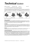
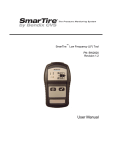
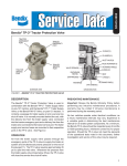
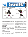
SD-06-1804
Bendix® SL-5™ Stop Light Switch & Bendix® DS-2™ Combined
Stop Light Switch & Double Check Valve
TERMINAL
LEAF
SPRING
RIVET
FULCRUM
BENDIX DS-2 VALVE
®
PISTON
CONTACT
STRIP
DIAPHRAGM
SHUTTLE VALVE
(CHECK VALVE)
™
SHORTING
BAR
BENDIX® SL-5™
STOP LIGHT SWITCH
INLET
PORT
INLET PORT
OUTLET PORT
FIGURE 1 - BENDIX® DS-2™ COMBINED STOP LIGHT SWITCH & DOUBLE CHECK VALVE SECTIONAL
DESCRIPTION
The Bendix® SL-5™ stop light switch is an electro-pneumatic,
5 psi, non-grounded switch that operates in conjunction with
the brake valve and stop lights. By completing the electrical
circuit, the SL-5 switch illuminates the stop lights when a
brake application is made.
The Bendix ® DS-2 ™ combined stop light switch and
double check valve—as the name implies—combines a
Bendix SL-5 stop light switch with a Bendix® DC-4® double
check valve to perform the function of both. It operates in
conjunction with the brake valve and hand control valve by
directing the flow of air, from whichever delivers the higher
pressure, into a common delivery line and to the stop light
switch, closing the electrical circuit to the stop lamps.
The stop light switch can be used with either 12 or 24 volt
systems.
The stoplight switch is not a serviceable item. If found
defective in either device, the complete unit must be
replaced.
The shuttle valve in the DS-2 valve is serviceable and may
be replaced.
Both the SL-5 switch and the DS-2 valve have been tested
and meet the requirements of FMVSS 121.
OPERATION
The stop switch mechanism is identical in the SL-5 switch
and the DS-2 valve.
When a brake application is made, air pressure from the
brake valve enters the cavity below the diaphragm. The
air pressure below the diaphragm moves the piston until
it contacts the leaf spring. The leaf spring travels past a
fulcrum at which point the leaf spring snaps a shorting bar
1
which mates with the contact strips. The stop light electrical
circuit is completed, illuminating the stop lights before the
brake application pressures reach 6 psi.
Note that the snap action spring design minimizes arcing.
The double check valve is activated by air being introduced
through either of the two (2) inlet ports. The greater
pressure pushes the shuttle along its guides and closes the
opposite inlet port. The air is then directed out the common
delivery line and to the stop light switch.
PREVENTIVE MAINTENANCE
Important: Review the Bendix Warranty Policy before
performing any intrusive maintenance procedures. A
warranty may be voided if intrusive maintenance is
performed during the warranty period.
No two vehicles operate under identical conditions; as
a result, maintenance intervals may vary. Experience is
a valuable guide in determining the best maintenance
interval for air brake system components. At a minimum, the
Bendix® DS-2™/SL-5™ valve should be inspected every six (6)
months or 1500 operating hours, whichever comes first, for
proper operation and electrical connections. Should the DS-2/
SL-5 valve not meet the elements of the operational tests
noted in this document, further investigation and service
of the valve may be required.
OPERATING AND LEAKAGE TEST
1. Install an accurate air gauge in the service line (or brake
chamber). Apply the brake valve gradually. The stop
lamps should light at 6 psi or less, and go out after the
brake application is released. This checks the electrical
function of the stop light switch in either the SL-5 switch
or DS-2 valve.
2. DS-2 valve only – Apply the foot valve and coat the
exhaust port of the hand valve (or other alternate
source). Reverse the above, applying the hand valve or
other alternate source, and coat the exhaust port of the
foot valve. In either mode, leakage must not exceed 100
sccm or a 1” bubble in not less than five (5) seconds.
3. SL-5 switch or DS-2 valve – When pressurized, leakage
must not exceed 20 sccm or a 1” bubble in not less than
10 seconds.
If the SL-5 switch or DS-2 valve does not function as
described above, or if leakage is excessive, the valve or
switch should be replaced with a new unit. In the case
of the double check portion of the DS-2 valve, it must
be repaired with genuine Bendix® service replacement
parts.
2
REMOVING AND INSTALLING
REMOVING
1. Block the vehicle wheels or hold by means other than
the vehicle service brakes.
2. Disconnect the electrical connections from terminal
screws.
3. SL-5 switch – Remove the switch using a wrench on
the hex portion of the body.
4. DS-2 valve – Disconnect the air lines and remove the
DS-2 valve.
INSTALLING
1. Replace the SL-5 switch or DS-2 valve in the port from
which it was removed. Do not install with the terminals
pointing down.
2. Secure the electrical connections.
3. Reinstall the air line connections to DS-2 valve.
DISASSEMBLY (Double Check Valve)
1. Remove three cap screws and cap.
2. Remove the o-ring seal from cap.
3. Remove the shuttle valve.
CLEANING AND INSPECTION
1. Blow dust or other foreign material out of the body. Do
not immerse in cleaning fluid.
2. Inspect the shuttle valve and o-rings for excessive wear
or deterioration. Inspect the valve seats for nicks or
burrs.
Replace all parts that were discarded, along with any parts
not found to be serviceable during inspection, using only
genuine Bendix replacement parts.
ASSEMBLY
Before assembling the DS-2 double check valve, lubricate
all o-rings and o-ring grooves with Bendix silicone lubricant
(Pc. No. 291126) or the equivalent.
NOTE: When using pipe thread sealant during assembly
and installation, take particular care to prevent the
sealant from entering the valve itself. Apply the
sealant beginning with the second thread back from
the end.
TEST
Repeat the “OPERATING AND LEAKAGE TEST” listed in
this document.
3
4
SD-06-1804_US_007 © 2013 Bendix Commercial Vehicle Systems LLC, a member of the Knorr-Bremse.Group. All Rights Reserved.