1
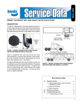
Bendix™ BlindSpotter®
Side Object Detection System
Installation Guide
Bendix™ BlindSpotter®
Side Object Detection System
BW2798 (Formerly VOIG0032)
April 2013
General
Table ofInformation
Contents
General Information
Warnings and Cautions........................................................................................2
FCC Compliance Statement
Federal Communications Commission .................................................................4
System Overview
Product Description .............................................................................................5
System Operation ................................................................................................6
Side Object Detection Display..............................................................................7
System Failure .....................................................................................................7
Installation Procedure
Sensor Location ...................................................................................................8
Sensor Orientation ...............................................................................................9
Mounting the Sensor ............................................................................................9
Side Object Display Mounting ............................................................................10
Component Connectors .....................................................................................11
Harness Connector Pin-Out ...............................................................................12
Harness Layout Diagram ...................................................................................13
Operation Testing
Testing System Operation ..................................................................................14
Testing Sensor Detection ...................................................................................15
Troubleshooting
System Fault Indication......................................................................................16
Red Detection LED Remains On........................................................................17
No Objects Detected ..........................................................................................18
No Audible Tone.................................................................................................19
System Does Not Power-Up ..............................................................................20
Wiring Diagrams ................................................................................................21
Specifications
Typical ...............................................................................................................23
Electrical ............................................................................................................23
Regulatory Compliance .....................................................................................24
Warranty
Manufacturer Limited Warranty ..........................................................................25
1
General Information
Warnings and Cautions
! WARNING
▲
Improper use of this system could lead to a serious accident. Read this entire
Installation Guide before operating the Bendix™ BlindSpotter® system. Pay
particular attention to the safety messages below. This guide should be used
in conjunction with proper training.
Limitations of Collision Warning Systems
The Bendix™ BlindSpotter® rear collision warning system is intended solely as an
aid for an alert and conscientious professional driver. It is not to be used or relied
upon to operate a vehicle. The system should be used in conjunction with rear view
mirrors and other instrumentation to maintain safe operation of the vehicle, ground
personnel, and adjacent property. A vehicle equipped with the Bendix™ BlindSpotter®
system should be operated in the same safe manner as if the system were not
installed. The system is not a substitute for normal safe driving procedures. It will
not compensate for any driver impairment, such as drugs, alcohol, or fatigue. Should
the system become inoperative, it could jeopardize the safety or lives of those who
depend on the system for safety.
! WARNING
▲
The system will not sense objects if the sensor view is obstructed. Therefore,
do not place objects in front of the system sensor. Remove heavy buildups of
mud, dirt, ice, and other materials.
Proper alignment is critical to correct operation of the system.
Testing and inspection of the system in accordance with these instructions
and record of the results should be listed on the daily maintenance report.
The units on operating vehicles must be tested each day (see the “Testing
System Operation” section) prior to the vehicle’s operation. Results of this
test must be recorded in the maintenance log.
People operating this equipment MUST check for proper operation at the
beginning of every shift or safety inspection period.
2
General Information
! WARNING
▲
People’s lives depend on the proper installation of this product in
conformance with these instructions. It is necessary to read, understand, and
follow all instructions shipped with the product.
Failure to follow all safety precautions and instructions may result in property
damage, serious injury, or death.
The Bendix™ BlindSpotter® system is intended for commercial use. Proper
installation of this system requires a good understanding of truck electrical
systems and procedures, along with proficiency in the installation.
Store these instructions in a safe place and refer to them when maintaining
and/or reinstalling the product.
3
FCC Compliance Statement
Federal Communications Commission
This device complies with Part 15 of the FCC (Federal Communications
Commission) rules. Operation is subject to the following two conditions: (1) This
device may not cause harmful interference and (2) this device must be able to
accept any interference received, including interference that may cause undesired
operation. Any interference that may be caused should be reported to the local FCC
field office or to the Federal Communications Commission; Enforcement Bureau;
445 12th Street S.W.; Room 7-C485; Washington, DC 20054.
Any changes or modifications made by the user to this equipment that are not
expressly approved by Bendix Commercial Vehicle Systems LLC could void
the user’s authority to operate the equipment.
Every effort has been made to ensure the accuracy of all information in this
brochure. However, Bendix Commercial Vehicle Systems LLC makes no expressed
or implied warranty or representation based on the enclosed information. Errors or
omissions should be reported to: Bendix Commercial Vehicle Systems LLC,
901 Cleveland Street, Elyria, OH 44035 or 1-800-AIR-BRAKE (1-800-247-2725).
4
System Overview
Product Description
The Bendix™ BlindSpotter® Side Object Detection System is a pulse-modulated radar
system capable of detecting the presence of other vehicles along side of the host
vehicle, aiding the driver's ability to avoid collisions while merging into adjacent lanes
of traffic.
A visual indicator, placed on the windshield pillar near the side view mirror provides
the driver with an additional tool for checking lane clearance next to the vehicle
before merging. When the driver signals to change lanes by activating the vehicle's
turn signal, the system will provide an audible tone along with a visual indication,
warning the driver that the lane next to the vehicle is not clear.
The BlindSpotter system is typically installed on the side opposite the driver, but can
be installed on both sides of the vehicle as well.
Note: Up to four sensors can be daisy chained to a single display unit for
applications that require an increased area of detection. Contact your OEM
parts dealer for information on purchasing additional sensors, brackets, and
harnessing.
5
System Operation
System Operation
The Bendix™ BlindSpotter® Side Object Detection System is powered by the vehicle's
ignition switch, and consists of a pulse-modulated radar sensor mounted to the side
of the vehicle coupled to a cab mounted display unit, that constantly monitors the
area within the radar's view for any objects present that may pose a collision hazard
during a lane change.
The pulse-modulated radar utilized in the BlindSpotter system will detect objects,
stationary or moving, while the vehicle is in motion or stopped. The radar's effective
range is approximately ten feet from the center view of the sensor.
6
System Operation
Side Object Detection Display
The display unit has two bright LED indicators used to display the system status. A
yellow LED indicates when the system is active, and a red LED indicates an object
is detected. An ambient light sensor automatically controls the intensity of the two
status LEDs, dimming them in low light conditions.
The display unit's built-in speaker provides an audible alert if an object is detected
when the vehicle's turn signal is activated. A button located on the front of the
display allows the driver to adjust the volume level.
Volume Control Button
Red Object Detected Indicator
Ambient Light Sensor
Yellow Power / Standby Indicator
System Failure
If the system detects a failure and becomes inoperative, the display unit will warn
the driver by continuously illuminating both the red and yellow LEDs at the same
time.
Refer to the troubleshooting section for more information about system failure.
7
Installation Procedure
Sensor Location
The Bendix™ BlindSpotter® Side Object Detection Sensor should be mounted on
the side of the vehicle, between 22 and 36 inches from the ground and at least 18
inches rear of the side view mirror (see diagram below).
Note: To reduce the possibility of the sensor detecting objects mounted to the
vehicle like the steps or fuel tanks, make sure the face of the sensor extends
out a minimum of 5/16 of an inch further than any other object within six (6)
inches of the sensor's body.
8
Installation Procedure
Sensor Orientation
The Bendix™ BlindSpotter® Side Object Detection Sensor should be orientated so
the embossed logo is parallel to the ground (see diagrams below). Orientation is
crucial for proper operation due to the radar's polarized beam profile.
9
Installation Procedure
Mounting the Sensor
The sensor should be mounted to the vehicle using 10-24 (6 mm) stainless steel
hardware. Bolts should be installed from the sensor side, with flat washers and
nylock nuts on the backside.
Torque hardware to a maximum of 22 lbs. in. Do not over torque.
10
Installation Procedure
Side Object Display Mounting
The Bendix™ BlindSpotter® Side Object Detection Display Unit should be mounted on
the inside of the cab to the windshield pillar. The display unit should be positioned in
line with the side view mirror on the same side of the vehicle as the sensor without
obstructing the driver's view.
! WARNING
▲
The Side Object Display Unit is not weather proof and must be mounted on the
inside of the cab. Failure to observe this warning will result in a void of warranty.
Vehicles with dual left and right side sensors will have a display mounted on both the
left and right windshield pillars.
11
Installation Procedure
Component Connectors
OPERATOR
DISPLAY
UNIT
4 1
ODU P1
3 2
CONNECTOR REAR
SIDE OBJECT
DETECTION SENSOR
6 1
5 2
4 3
CONNECTOR REAR
12
Installation Procedure
Harness Connector Pin-Out
J1 - Deutsch Part Number DT04-4P
Pin 1
J2 - Pin 4
Pin 2
J2 - Pin 5
Pin 3
J2 - Pin 3
Pin 4
Turn Signal Input
J2 - Deutsch Part Number DT04-6P
Pin 1
Ignition Power
Pin 2
Chassis Ground
Pin 3
J1 - Pin 3
Pin 4
J1 - Pin 1
Pin 5
J1 - Pin 2
Pin 6
Not Used
13
Installation Procedure
Harness Layout Diagram
14
Operation Testing
Testing System Operation
1. Before testing the system, move the vehicle to an area where there are no
objects within a minimum of a 15-foot radius of the sensor.
2. Turn the vehicle's ignition to the on position (do not start vehicle).
! WARNING
▲
Observe proper safety procedures by making sure the vehicle's parking brakes are
set and the engine is off before performing any tests.
3. Observe the side sensor display unit's red and yellow indicators and refer to
the table below for proper power-up and system operation. Have an assistant
walk within ten feet of the front of the sensor to test for object detection.
System Status
Power-up (initial display test)
Power-up (initial sensor test)
No Objects Detected
Object Detected
Object Detected (turn signal active)
System Failure
Display Indicator
Red and Yellow (< 5 sec.)
Red only (< 5 sec.)
Yellow only
Red only
Red only (tone)
Red and Yellow
4. To test the audible warning, activate the turn signal while testing the object
detection. The warning tone is only heard once for each activation of the turn
signal.
5. If the red and yellow LEDs remain on continuously for more than five
seconds after the initial power-up, this is an indication the system has
detected a failure. Refer to the troubleshooting section for more information.
15
Operation Testing
Testing Sensor Detection
To test the sensor's maximum effective detection capabilities, use a flat metallic
object with a minimum surface area of one (1) square foot, and hold it facing the
sensor at the following positions using the diagram below as a reference.
1. Six (6) feet out from center.
2. Six (6) feet out, six feet left from center.
3. Six (6) feet out, six feet right from center.
4. Ten (10) feet from center (maximum effective distance).
The effective detection zone of the sensor can be drawn as a ten (10)-foot arc,
± 45 degrees from center. The sensor may detect objects beyond this zone, shown
in dark grey above, but should not be considered reliable.
Note: The ability of the sensor to detect objects in its effective detection
zone depends on the object's size, composition, and its ability to reflect
electromagnetic energy.
16
Troubleshooting
System Fault Indication
If both the red and yellow LEDs remain illuminated continuously after five seconds
of initial power-up, or anytime during normal operation, this is an indication that the
system has detected a failure with the radar sensor or a loss of communications
between the sensor and the side sensor display.
1. Disconnect the sensor and the side object display from the harness and check
the connectors for corrosion, or damage to the harness.
2. Using an ohm meter, check the harness for a short to ground by testing the
resistance from J1 Pin 3 and J2 Pin 3 to chassis ground. This reading should
be greater than 100K ohms or infinite.
3. Using an ohm meter, check the communications link between the sensor and
the side object display for continuity by testing the resistance from J1 Pin 3 to
J2 Pin 3 (see diagram below). This reading should be less than 0.9 ohms.
J1
Display
J2
Sensor
17
Troubleshooting
Red Detection LED Remains On
If after the initial five second system power-up test, the red detect indicator remains
illuminated constantly, even when no objects are present in the radar sensors
detection zone, either the radar sensor is improperly mounted or has malfunctioned.
1. Review the sensor installation section in this manual to verify proper sensor
positioning, orientation, and mounting.
2. Make sure there are no other surfaces or objects on the vehicle, like steps, fuel
tanks, mirrors, that extend beyond the face of the radar sensor that may be
interfering with the sensor's operation.
3. Remove the sensor from the vehicle and inspect it for any damage. Inspect the
connector for any signs of damage or corrosion.
4. Connect the sensor to the harness and hold it away from the vehicle into an
open area away from any objects. Power up the system and check for proper
operation.
18
Troubleshooting
No Objects Detected
If after the initial system power-up the sensor does not appear to detect any objects,
the radar sensor may have malfunctioned. Refer to the Testing System Operation
section in this manual.
1. Hold and aim a test object six (6) feet out from center, directly at the sensor,
and verify if the side object display indicates the object has been detected.
2. Continuing to hold the test object six (6) feet from the sensor, refer to the
diagram below and move six (6) feet to the right and then to the left of center
from the sensor, keeping the test object positioned directly at the face of the
sensor. Verify if the side object display indicates the object has been detected
in both extreme positions.
3. Hold and aim the test object ten (10) feet out from center, directly at the sensor,
and verify if the side object display indicates the object has been detected.
19
General Information
Troubleshooting
No Audible Tone
When an object is detected while the vehicle's turn signal is active, but the side
object display does not emit an audible tone, either the system is improperly wired
or the side object display has malfunctioned.
1. With the vehicle's ignition switch in the off position, disconnect the display
connector (J1) and use an ohm meter to test the continuity between pin 1
and the turn signal source point.
J1
Display
2. Turn the vehicle's ignition switch to the on position and activate the vehicle's
turn signal, on the same side of the vehicle the side object sensor is located,
and use a volt meter to check for the turn signal voltage between pins 2 and 4.
J1
Display
20
Troubleshooting
System Does Not Power-Up
When the vehicle's ignition switch is turned to the on position and the side object
display fails to power-up, either the system's fuse has blown, the harness is wired
improperly or damaged, or the system has malfunctioned.
1. Check the system's inline one amp fuse.
2. With the vehicle's ignition switch in the off position, disconnect the sensor
connector (J2). Use a voltmeter to test for ignition voltage between pins
1 and 2. Check the connector pins for corrosion or damage.
J2
Sensor
3. Re-connect the sensor connector (J2) to the harness and then disconnect the
display connector (J1). Use a voltmeter to test for ignition voltage between pins
1 and 2 at the display connector. Check the connector pins for corrosion or
damage.
J1
Display
21
SIDE OBJECT
DETECTION SENSOR
22
INTERCONNECT
HARNESS
J1 ODU
GROUND
IGNITION
TURN SGNL
ODU PWR
ODU GND
ODU COMM
TURN SIGNAL
CONNECTOR REAR
3 2
4 1
J1
Display
ODU PWR
ODU GND
COMM
PWR
GND
CONNECTOR REAR
4 3
5 2
6 1
J2
Sensor
J2 SOD
ODU P1
OPERATOR
DISPLAY
UNIT
Troubleshooting
Wiring Diagrams
1
2
3
SIDE
SENSOR
SENSOR
CONNECTOR FRONT
6
5
4
J2
3
4
5
GND
COMM
ODU PWR
ODU GND
6
1
2
PWR
BROWN
DK GREEN
WIRING DIAGRAM
RED
BLACK
WHITE
RED
BLACK
TURN SIGNAL
J2 SOD
GROUND
IGNITION
ORANGE
WHITE
BROWN
DK GREEN
1
2
4
3
TURN SIG
ODU COMM
ODU GND
ODU PWR
OPERATOR
DISPLAY
UNIT
240 INCHES
TURN SGNL
72 INCHES
J1 ODU
IGNITION
GROUND
1
2
DISPLAY
CONNECTOR FRONT
4
3
J1
Troubleshooting
23
Specifications
Typical:
Electronics
Solid state
Sealing
Encapsulated to protect from dust, moisture, and
vibration.
Operating Temperature
-40°F to +185°F (-40°C to +85°C)
Sensor
Pulsed RF transmitter at 5.8 GHz
Material
Weight
Dimensions
Mounting
Polycarbonate radome with aluminum back plate
1.25 lbs. (0.57 kg)
5.25" (13.3 cm) diameter x 1.375" (3.5 cm) deep
3 - 0.188 (4.8 mm) diameter mounting holes
Operator Display Unit (ODU)
Material
Weight
Dimensions
Mounting
Polycarbonate / ABS alloy
.25 lbs. (.11 kg)
1.00" (2.5 cm) height x 2.25" (5.7 cm) width x
2.00" (5.1 cm) depth
User dependent
Electrical:
Input Voltage
9 - 33 volts DC
Input Current
0.25 amp maximum (fused at 1 amp)
Polarity
Polarity protected
Power Connection
2 - 18 AWG wires
Turn Signal Connection
1 - 18 AWG wire
24
Specifications
Regulatory Compliance:
Compliant with
FCC Part 15.249 (5725-5875 MHz)
FCC ID
OXZSTDPREVIEW
25
Warranty
Manufacturer Limited Warranty
The Bendix standard warranty specific to retrofit systems is 12 months/100,000
miles when the product is installed on its intended application. The limited warranty
does not cover defects or damage caused by abuse, misuse, road debris, accidents
or improper installation, maintenance or service.
Note: Some exclusions do apply. Refer to the Bendix Limited Warranty VORAD®
Collision Warning System (BW2759) for complete warranty information visit
www.bendix.com or call 1-800-AIR-BRAKE (1-800-247-2725).
26
27
Bendix Commercial Vehicle Systems LLC
901 Cleveland Street
Elyria, Ohio 44035
1-800-247-2725
BW2798 ©2013 Bendix Commercial Vehicle Systems LLC, a member of the Knorr-Bremse Group
All Rights Reserved • 04/13