1
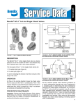
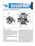
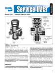
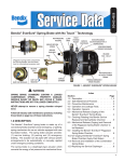
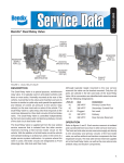
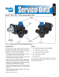
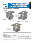
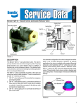
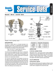
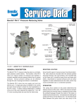
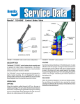
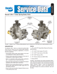
SD-03-9043
Bendix® SR-7® Spring Brake Modulating Valve
MOUNTING
STUDS (2)
41
BALANCE
PORT
4-1
PARK CONTROL
(FROM DASH VALVE)
42
CONTROL
PORT
2
DELIVERY
EXHAUST
1
SUPPLY PORT
3
EXHAUST
2
DELIVERY
PIPE PLUG
(INCLUDED IN QUICK
RELEASE VALVE
APPLICATIONS)
FIGURE 1 - EXTERIOR VIEW
DESCRIPTION
3. Prevents compounding of service and spring forces.
The Bendix® SR-7® spring brake modulating valve is used
in conjunction with a dual air brake system and spring brake
actuator and performs the following functions:
The valve has one park control, one service control, one
supply, one balance, four delivery NPTF ports, and an
exhaust port protected by an exhaust diaphragm. The
valve incorporates two mounting studs for mounting the
valve to the frame rail or cross member (where applicable).
1. Provides a rapid application of the spring brake actuator
when parking.
2. Modulates the spring brake actuator application using
the dual brake valve should a primary failure occur in
the service brake system.
1
MAIN PISTON
CONTROL PISTON
DOUBLE CHECK VALVE
O-RING
SPRING GUIDE
CHECK VALVE
COVER
UPPER BODY
RETAINING RING
O-RING
PARK CONTROL
PORT
O-RING
SPACER
IN-LINE SINGLE CHECK
VALVE
MAIN PISTON SPRING
STATIC PISTON
SPRING
O-RING
O-RING
O-RING
SUPPLY PORT
STATIC PISTON
SPRING
O-RING
CHECK VALVE
GUIDE
O-RING
O-RING
O-RING
LOWER BODY
BALL CHECK
VALVE
SPRING
VALVE RETAINER
SPRING
O-RING
1/4-20 MACHINE
SCREWS
O-RING
INLET / EXHAUST
VALVE
VALVE SEAT
LOWER VALVE GUIDE
RETAINING RING
EXHAUST
PORT
DIAPHRAGM
RETAINING RING
#10 TORX HEAD SCREW
DIAPHRAGM WASHER
FIGURE 2 - SECTIONAL VIEW OF SR-7® SPRING BRAKE MODULATING VALVE USED IN RELAY VALVE APPLICATIONS
OPERATION
The operation guidelines shown in this manual represent
the relay valve based Bendix® SR-7® (refer to system
schematic shown in figure 3). A quick release based valve
functions similarly to the relay valve based version with
2
the exception that all air delivered to spring brakes passes
through the park control port through the in-line single
check valve. The SR-7® quick release style can be easily
identified by the pipe plug in the supply port of the valve.
PP-DC®
VALVE
SYSTEM FOR A 4X2 OR 6X4
STRAIGHT TRUCK WITH
PP-DC® PARKING CONTROL
R-12® Relay Valve
SR-7® valve w/
single check valve
Ref: 5010914
FIGURE 3 - SYSTEM SCHEMATIC WITH PP-DC® PARK CONTROL
PP-1®
VALVE
SYSTEM FOR A 4X2 OR 6X4
STRAIGHT TRUCK WITH
PP-1® PARKING CONTROL
®
R-12 Relay Valve
SR-7® valve w/ out
single check valve
DC-4®
VALVE
FIGURE 4 - SYSTEM SCHEMATIC WITH PP-1® PARK CONTROL AND DC-4® DOUBLE CHECK VALVE
3
CONTROL LINE PRESSURE
BALANCE PORT
SECONDARY RESERVOIR
CONSTANT PRESSURE
CONTROL PORT
DELIVERY TO SPRING BRAKES
INLET / EXHAUST VALVE OPEN
FIGURE 5 - CHARGING LESS THAN 107 PSI
CHARGING SPRING BRAKE ACTUATORS BELOW
107 PSI (FIGURE 5)
CHARGING SPRING BRAKE ACTUATORS ABOVE
107 PSI (FIGURE 6)
With the air brake system charged and the parking brakes
released (by pushing the dash valve button in), air enters
the park control port. This opens the Bendix® SR-7® valve
to supply air pressure to the spring brake chambers. As
illustrated, air pressure in the chambers is below 107 psi
(nominally).
Once the SR-7® valve delivery pressure reaches 107 psi
(nominal), the inlet and exhaust are closed (valve lap
position). This maintains the spring brake hold-off pressure
at 107 psi (nominal).
CONTROL LINE PRESSURE
BALANCE PORT
SECONDARY RESERVOIR
CONSTANT PRESSURE
CONTROL PORT
DELIVERY TO SPRING BRAKES
INLET / EXHAUST VALVE SEATED
FIGURE 6 - CHARGING GREATER THAN 107 PSI
4
CONTROL LINE PRESSURE
BALANCE PORT - PRIMARY
CIRCUIT PRESSURE
SECONDARY RESERVOIR
CONSTANT PRESSURE
CONTROL PORT - SECONDARY
CIRCUIT PRESSURE
DELIVERY TO SPRING BRAKES
INLET / EXHAUST VALVE SEATED
FIGURE 7 - NORMAL SERVICE APPLICATION
NORMAL SERVICE APPLICATION (FIGURE 7)
PARKING (FIGURE 8)
During a service brake application, the valve remains in
the lap position. The Bendix® SR-7® valve monitors the
presence of air pressure in both primary and secondary
delivery circuits.
Actuating the park brakes (by pulling the dash valve button
out) exhausts spring brake air pressure through the SR-7®
valve exhaust port.
MAIN AND CONTROL PISTONS MOVE UP
CONTROL LINE PRESSURE
BALANCE PORT
SECONDARY RESERVOIR
CONSTANT PRESSURE
CONTROL PORT
AIR EXHAUSTS FROM
SPRING BRAKES
INLET VALVE SEATED
FIGURE 8 - PARKING
5
MAIN PISTON MOVES UP
CONTROL LINE PRESSURE
BALANCE PORT - LOSS OF
PRIMARY CIRCUIT PRESSURE
SECONDARY RESERVOIR
CONSTANT PRESSURE
CONTROL PORT - SECONDARY
CIRCUIT PRESSURE
AIR EXHAUSTS FROM
SPRING BRAKES
INLET VALVE SEATED
FIGURE 9 - SERVICE APPLICATION LOSS OF PRIMARY CIRCUIT
SERVICE APPLICATION WITH LOSS OF AIR IN
PRIMARY CIRCUIT (FIGURE 9)
SERVICE APPLICATION WITH LOSS OF AIR IN
SECONDARY CIRCUIT (FIGURE 10)
With the parking brakes released (dash valve button in)
and the absence of air in the primary circuit delivery,
a service brake application from the secondary circuit
causes the pressure in the spring brakes to be exhausted
proportionally to this application. This is known as spring
brake modulation. A 30 psi service brake application will
exhaust the spring brake pressure to approximately 60 psi.
With the parking brakes released (dash valve button in)
and the absence of air in the secondary circuit reservoir,
the external single check valve in the supply port seals to
prevent air leakage to atmosphere from the Bendix® SR-7®
valve. The dash valve delivery air flows through the in-line
single check valve and becomes SR-7® valve supply air.
This air is delivered to maintain at least 107 psi (nominal)
in the spring brake chambers.
CONTROL LINE PRESSURE
IN-LINE SINGLE
CHECK VALVE
SECONDARY RESERVOIR
NO PRESSURE
BALANCE PORT - PRIMARY
CIRCUIT PRESSURE
CONTROL PORT - LOSS OF
SECONDARY CIRCUIT PRESSURE
DELIVERY TO
SPRING BRAKES
FIGURE 10 - SERVICE APPLICATION LOSS OF SECONDARY CIRCUIT
6
NO CONTROL LINE
PRESSURE
BALANCE PORT PRIMARY CIRCUIT PRESSURE
SECONDARY RESERVOIR
CONSTANT PRESSURE
CONTROL PORT SECONDARY CIRCUIT PRESSURE
DELIVERY TO SPRING BRAKES
INLET / EXHAUST VALVE OPEN
FIGURE 11 - ANTI-COMPOUNDING
ANTI COMPOUNDING (FIGURE 11)
OPERATING TEST
The Bendix® SR-7® valve provides anti-compounding of the
service and spring brake forces. When the park brakes are
actuated (by pulling the dash valve button out), a service
brake application will cause the SR-7® valve to deliver air
pressure to the spring brake chambers. Thus the vehicle is
held stationary using a service brake application. When the
service brake application is released, the delivery pressure
is exhausted from the spring brake chambers and the
vehicle remains parked using the spring brake actuators.
Block vehicle and hold by means other than vehicle brakes.
Charge air brake system to governor cut-out pressure.
1. Place parking control valve in “park” position. Observe
that spring brake actuators apply promptly. Remove
one line from delivery port of the SR-7® valve and install
test gauge known to be accurate. Place parking control
valve in “release” position. Observe that spring brake
actuators release fully.
PREVENTIVE MAINTENANCE
2. With parking control valve in “release” position, note
gauge pressure reading. (Correct spring brake actuator
hold-off pressure is 107 psi nominally.)
Important: Review the Bendix Warranty Policy before
performing any intrusive maintenance procedures. A
warranty may be voided if intrusive maintenance is
performed during the warranty period.
3. Place parking control valve in “park” position - gauge
reading should drop to zero promptly. A lag (more than
3 seconds) in drop of pressure would indicate faulty
operation.
No two vehicles operate under identical conditions; as
a result, maintenance intervals may vary. Experience is
a valuable guide in determining the best maintenance
interval for air brake system components. At a minimum,
the SR-7® valve should be inspected every 6 months or
1500 operating hours, whichever comes first, for proper
operation. Should the SR-7® valve not meet the elements
of the operational tests noted in this document, further
investigation and service of the valve may be required.
4. With the parking control valve in the “park” position,
gradually apply foot brake valve and note a pressure
reading increase on the gauge installed in the SR-7®
valve delivery port.
5. Place parking control valve in “release” position.
6. Drain the reservoir, which supplies the rear service
brake circuit, apply the foot brake valve several times
and note that pressure reading on gauge decreases
each time foot brake valve is applied (spring brake
modulation). After the foot brake valve has been
applied several times, pressure on gauge will drop to
the point where release of the spring brake actuators
will no longer occur.
7
LEAKAGE TEST
Place the park control valve in the “release” position; using
a soap solution, coat all ports including the exhaust port. A
1" bubble in 3 seconds is permitted (175 SCCM).
If the valve does not function as described, or if leakage
is excessive, it is recommended that it be replaced with a
new or remanufactured unit available from a Bendix parts
outlet. DO NOT ATTEMPT TO DISASSEMBLE THE
SR-7® VALVE. THE VALVE CONTAINS HIGH SPRING
FORCES THAT COULD RESULT IN PERSONAL INJURY
IF DISASSEMBLY IS ATTEMPTED!
SERVICING THE SR-7® VALVE
GENERAL SAFETY GUIDELINES
WARNING! PLEASE READ AND FOLLOW
THESE INSTRUCTIONS TO AVOID PERSONAL
INJURY OR DEATH:
6. Never exceed manufacturer’s recommended
pressures.
7. Never connect or disconnect a hose or line
containing pressure; it may whip. Never remove
a component or plug unless you are certain all
system pressure has been depleted.
8. Use only genuine Bendix® brand replacement parts,
components and kits. Replacement hardware,
tubing, hose, fittings, etc. must be of equivalent
size, type and strength as original equipment and
be designed specifically for such applications and
systems.
9. Components with stripped threads or damaged
parts should be replaced rather than repaired. Do
not attempt repairs requiring machining or welding
unless specifically stated and approved by the
vehicle and component manufacturer.
WHEN WORKING ON OR AROUND A VEHICLE, THE
FOLLOWING GENERAL PRECAUTIONS SHOULD BE
OBSERVED AT ALL TIMES.
10. Prior to returning the vehicle to service, make
certain all components and systems are restored
to their proper operating condition.
1. Park the vehicle on a level surface, apply the
parking brakes, and always block the wheels.
Always wear safety glasses.
11. For vehicles with Automatic Traction Control (ATC),
the ATC function must be disabled (ATC indicator
lamp should be ON) prior to performing any vehicle
maintenance where one or more wheels on a drive
axle are lifted off the ground and moving.
2. Stop the engine and remove ignition key when
working under or around the vehicle. When
working in the engine compartment, the engine
should be shut off and the ignition key should be
removed. Where circumstances require that the
engine be in operation, EXTREME CAUTION should
be used to prevent personal injury resulting from
contact with moving, rotating, leaking, heated or
electrically charged components.
VALVE REMOVAL
1. Prior to removing the SR-7® valve, apply the parking
brakes and drain all the vehicle reservoirs.
2. Identify all air lines before disconnecting.
3. Remove the two mounting nuts that secure the valve
to the frame rail and remove the valve.
VALVE INSTALLATION
3. Do not attempt to install, remove, disassemble
or assemble a component until you have read
and thoroughly understand the recommended
procedures. Use only the proper tools and observe
all precautions pertaining to use of those tools.
4. If the work is being performed on the vehicle’s
air brake system, or any auxiliary pressurized air
systems, make certain to drain the air pressure
from all reservoirs before beginning ANY work
on the vehicle. If the vehicle is equipped with a
Bendix® AD-IS® air dryer system or a dryer reservoir
module, be sure to drain the purge reservoir.
1. Align the mounting studs with the mounting holes on
the vehicle frame rail. Tighten the mounting nuts to
180-220 in. lbs.
2. Install the valve onto the vehicle ensuring all ports are
connected as marked during disassembly.
TESTING THE REPLACEMENT SR-7® SPRING
BRAKE MODULATING VALVE
Perform operating and leakage tests as outlined in
“Operating Tests” section.
5. Following the vehicle manufacturer’s recommended
procedures, deactivate the electrical system in a
manner that safely removes all electrical power
from the vehicle.
8
BW2271 © 2011 Bendix Commercial Vehicle Systems LLC 1/2011. Printed in U.S.A. All rights reserved.