1
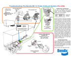
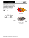
Troubleshooting The Bendix® MC-12 Trailer AntiLock System (Post 2/98)
Ground
A
B
C
D
E
Stop Lamp Power
Constant Power
In Cab Status Light
Trailer Status Light
Ground
OPERATIONAL INFORMATION
The EC-12 controller houses the
electronics that regulate the antilock
system. The EC-12 contains a diagnostic
window and a 14 pin connector.
7 PIN CONNECTOR
STATUS INDICATOR
Front
Back
Constant
Power
Stop Light
Power
Diagnostic
Window
In Cab Status
Light
Connector
ANTILOCK
INDICATOR
MC-12 Modulator
Controller
(Ref. SD-13-4762)
IF INDICATOR REMAINS ILLUMINATED
SYSTEM REQUIRES SERVICE
WHEEL SPEED SENSOR
CONNECTOR
Resistance Across Pins
1500 - 2500 ohms
(Ref. SD-13-4754)
Tie Wrap
Wheel Speed
Sensor
Mounting
Block
TYPICAL
TRAILER AXLE
The EC-12 mounts on the M-12 modulator
with four bolts and it is internally connected
to the solenoids by a four pin connector.
Sensors mounted at the wheel end send
wheel speed information to the EC-12
through the 14 pin connector. If wheel lock
up is impending, the EC-12 commands the
solenoids to modulate brake chamber
pressure on the axle(s) in which the system
is installed. The MC-12 modulator controller
receives power and ground from the vehicles
electrical system. During start up, trailer
antilock immediately runs a self check. The
trailer status light flashes once and then goes
off. Should a problem occur, the status light
comes on and remains on.
TROUBLESHOOTING
If the status light remains on, inspect the
EC-12 for illuminated LEDs. If no status light
was installed, the diagnostic LEDs should
be checked periodically.
Reset controller with magnet after repair.
IF THESE LED'S
ARE ILLUMINATED
CHECK THE VEHICLE WIRING HARNESS CONNECTOR
FOR THE PROPER RESISTANCE WITH
STOP LAMP POWER OFF
MC-12 Controller Cable Assembly
To Controller
D
C
A
SENSOR 1
B
PNMLKJH
GFEDCBA
N - P 15 -2500 Ohms
E
A
B
C
D
E
Stop Lamp Power
Constant Power
In Cab Status Lamp
Trailer Status Lamp
Ground
PNMLKJH
GFEDCBA
L - M 15 -2500 Ohms
9.5 - 11.5
Ohms
White to White
9.5 - 11.5
Ohms
Black to Black
MODULATOR
Sensor
Sensor
Sensor
Sensor
Sensor 2 (yellow)
Sensor 2 (yellow)
Sensor 1 (blue)
Sensor 1 (blue)
SENSOR 2
Stop Lamp Power
Constant Power
Ground
Trailer Status Lamp
Cab Status Lamp (optional)
2
2
1
1
Vehicle wire harness
Most Commonly Encountered Problems That Result In LEDs Being Illuminated.
Repair or Replacement Components As Necessary
• Damaged connectors or wires, caused by dangling or loose wires not properly restrained.
• Power connection not capable of supplying 12 volts at 3 amps because of a poor connection,
bad crimp
• Corroded connectors and connections not properly sealed or seated.
• Terminals not completely latched or sealed into connectors; harness connector bolt not tight.
• Improperly spliced connection repair or repair not sealed properly.
• Excessive sensor air gap, sensor bushing tension or excessive bearing end play.
(Gently push sensor against exciter ring, or readjust bearings)
• Non functioning antilock components, sensor, controller, modulator.
Additional Servicing Tips
VOLTAGE
w/STOP
LAMP
POWER
PNMLKJH
GFEDCBA
• Do not pierce wires with probes when troubleshooting harnesses.
• Gently probe terminals when checking for resistances, do not deform
contacts
• Apply nonconductive dielectric grease to any and all
connectors if inspecting or disconnecting connectors.
• If excessive cable length is present, bundle and
tie wrap neatly to adjacent air lines or
framing members.
A - C 9 to 18 Volts DC
B - C 9 to 18 Volts DC
ECU
CONTROLLER
Replace Controller
All CONTACT OF THE 14 PIN CONNECTOR ABOVE SHOULD NOT HAVE ANY CONTINUITY
TO THE GROUND CONTACT "C". CONTACTS "A" & "B" ARE POWER TO THE MC-12
BW1959 © Bendix Commercial Vehicl Systems LLC 2/2000 • Printed in USA • All Rights Reserved
ADDITIONAL INFORMATION:
1-800-247-2725-2-1
Visit: www.bendix.com