1
SD-13-4761
®
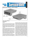
Bendix® MC-11™ Tractor AntiLock
14-PIN
CONNECTOR
LED DIAGNOSTIC
DISPLAY
EC-11™
CONTROLLER
CONTROL
M-12™
MODULATOR
SUPPLY
DELIVERY
DELIVERY
FIGURE 1
DESCRIPTION
The Bendix® MC-11™ tractor antilock assembly is designed
to improve vehicle stability by reducing wheel lock-up during
aggressive braking. Like the MC-10™ antilock assembly that
it replaces, the MC-11™ tractor antilock assembly is a
one-channel system–it uses one modulator. And the system
can control single or tandem axles. The antilock assembly
mounts to the vehicle frame and usually replaces the drive
axle service relay valve.
The MC-11™ tractor antilock assembly consists of an EC-11™
electronic controller and an M-12™ modulator. The EC-11™
controller houses the electronics that regulate the antilock
system. The electronics are protected by a self-healing
silicone compound. The EC-11™ controller contains a
diagnostic window and reset switch, and its 14 pin connector
is the electrical link to the rest of the antilock system. (See
Figure 2.) The controller mounts to the modulator with four
cap screws, and it is electrically connected to the modulator
with a four-pin connector. The M-12™ modulator has two
components: solenoids, which rapidly apply and exhaust
air during an antilock stop, and a standard relay valve. (See
SD-13-4772 for more information on the M-12™ modulator.)
The air connections for the MC-11™ tractor antilock assembly
are as follows:
AIR CONNECTION
EMBOSSED
IDENTIFICATION
Supply
(to reservoir)
Delivery
(to brake actuator)
Control
(to rear service brake valve delivery)
SUP
DEL
CON
1
14 PIN CONNECTOR CALLOUTS
PIN
CONNECTION
A
B
“+” POWER
RETARDER DISABLE
C
D
“-” GROUND
DASH LIGHT
E
F
SERIAL LINK
SERIAL LINK
G
H
UNUSED
UNUSED
J
K
UNUSED
UNUSED
L
M
SENSOR
SENSOR
N
P
SENSOR
SENSOR
14-PIN CONNECTOR
GROUND
EXH. BLK. PWR
EXH. BLK. GRD
EXH. WHT. PWR
EXH. WHT. GRD
POWER
SENSOR
RETARDER
DASH LIGHT
SERIAL LINK
14-PIN
CONNECTOR
FIGURE 2 - TYPICAL MC-11™ TRACTOR ANTILOCK WIRING SCHEMATIC
2
SENSOR
DOUBLE
CHECK VALVE
EXHAUST
SOLENOID
TRAILER
CONTROL
VALVE
BRAKE
VALVE
CONTROL
INLET SOLENOID
PISTON
RESERVOIR
DELIVERY
SUPPLY
EXHAUST
BRAKE
CHAMBER
FIGURE 3 - APPLYING: NORMAL SERVICE APPLICATION
The wiring connections on the 14 pin connector are as
follows:
PIN A - Power
PIN IF - Serial Link
PIN B - Retarder Disable
PIN L - Sensor
PIN C - Ground
PIN M - Sensor
PIN D - Dash Light
PIN N - Sensor
PIN E - Serial Link
PIN P - Sensor
PIN A - Vehicle power is supplied to the EC-11™ controller
from the ignition switch, through a fuse, to pin A on
the 14 pin connector.
PIN B - The EC-11™ controller is equipped with a retarder
disable circuit, which, when coupled with an
electrical relay, will disable the vehicle retarder
(engine or transmission) during an antilock stop.
The retarder disable function is not essential but is
highly recommended for vehicles equipped with a
retarder.Connection to pin B on the EC-11™
controller provides this function.
PIN C - Pin C connects directly to negative vehicle ground.
PIN D - A dash light and its electrical relay are controlled
by the EC-11™ controller through pin D. The light
advises the driver of the antilock system condition.
PIN E - The serial link allows the EC-11™ controller to “report”
its operating PIN IF condition to a specialized
external computer in response to certain commands
it receives. The serial link configuration conforms to
S.A.E. standard J1708. Pins E and F provide serial
link connections to the EC-11™ controller, but the
function is not essential for MC-11™ tractor antilock
assembly operation.
PIN L - Sensors mounted at the wheel end send wheel
speed information PIN M to the EC-11™ controller
through pins L-M and N-P. The EC-11™ controller
receives the information at (PIN N) 100 pulses per
wheel revolution.
The MC-11™ tractor antilock assembly “knows” what’s
happening at the wheel ends because of the signals it
receives from the wheel speed sensors. The sensors are
actually A.C. generators. They create a magnetic field; and
when the field is interrupted by an irregular surface, like a
tone ring, A.C. voltage is produced. The frequency of voltage
increases or decreases as wheel speed increases or
decreases.
During normal, non-antilock operation, the M-12™ modulator
inlet solenoid is open, and the exhaust solenoid is closed.
In this condition, the M-12™ modulator is a regular R-12™
relay valve. It receives a control signal from the foot valve,
3
DOUBLE
CHECK VALVE
EXHAUST
SOLENOID
TRAILER
CONTROL
VALVE
BRAKE
VALVE
CONTROL
INLET SOLENOID
PISTON
RESERVOIR
DELIVERY
SUPPLY
BRAKE
CHAMBER
EXHAUST
FIGURE 4 - BALANCED POSITION
which passes through the open inlet solenoid and into the
control cavity of the relay valve. The valve then applies air to
the service brake chambers in proportion to the control signal.
If wheel lock is impending, the EC-11™ electronic controller
commands the solenoids to modulate brake chamber
pressure on the axles in which the system is installed.
OPERATION
APPLYING: Normal Service Application
When a normal service brake application is made, control
air pressure from the brake valve enters the modulator
control port. The air passes through the supply solenoid
and acts on the modulator’s piston. The piston closes the
modulator exhaust and opens the inlet, delivering supply air
out the delivery ports.
BALANCED POSITION: Normal Service Application
solenoid housing and out the exhaust port of the brake valve.
As the piston moves upward, the modulator’s exhaust opens,
allowing air from the piston’s underside to exhaust through
the modulator exhaust port.
ANTILOCK MODE: Solenoids Activated
If a service brake application is made and the EC-11™
controller senses impending wheel lockup, it will command
the antilock system to alter the service brake application
automatically.
When activated, shuttles within the solenoids alter the
application and exhaust of control air pressure. The supply
solenoid closes, preventing control line pressure from
entering the modulator. Then the exhaust solenoid opens,
allowing control pressure to exhaust from the top side of
the piston through the exhaust port of the solenoid assembly.
This activity occurs in a pulsating manner, simulating
“pumping of the brakes.”
The modulator reaches a balanced position when control
pressure acting upon the topside of the piston approaches
that of the air acting upon the underside of the piston. The
piston moves upward and closes the inlet valve, while the
exhaust remains closed. This prevents the modulator from
delivering or exhausting air.
PREVENTIVE MAINTENANCE
EXHAUSTING: Normal Service Application
EVERY 3 MONTHS; 25,000 MILES; 900 OPERATING
HOURS; OR DURING THE VEHICLE CHASSIS
LUBRICATION INTERVAL
When the brake valve is released, control pressure exhausts
through the supply solenoid and the check valve in the
4
GENERAL
Perform the inspections and tests at the prescribed intervals.
If the MC-11™ tractor antilock assembly fails to function as
described, repair or replace the unit.
DOUBLE
CHECK VALVE
EXHAUST
SOLENOID
TRAILER
CONTROL
VALVE
BRAKE
VALVE
CONTROL
INLET SOLENOID
PISTON
RESERVOIR
DELIVERY
SUPPLY
BRAKE
CHAMBER
EXHAUST
FIGURE 5 - EXHAUSTING: NORMAL SERVICE APPLICATION
1. Remove any accumulated contaminants and visually
inspect the exterior of the unit for excessive corrosion or
physical damage.
5. If leakage is excessive around the supply and exhaust
solenoids, replace the M-12™ modulator.
2. Inspect all air lines and wiring connected to the MC-11™
tractor antilock assembly for signs of wear or physical
damage. Replace as necessary.
LED Operation
3. Perform “LEAKAGE TEST.”
EVERY YEAR; 100,000 MILES; OR 3,600 OPERATING
HOURS
1. Perform “OPERATIONAL AND LEAKAGE TESTS.”
OPERATIONAL AND LEAKAGE TESTS
LEAKAGE TEST
1. Park the vehicle on a level surface and block the wheels.
Release the parking brakes and build the air system to
full pressure.
2. Turn the engine OFF and make 4 or 5 brake applications.
Note that the service brakes apply and release promptly.
3. Build system pressure to governor cut-out and turn engine
OFF.
4. Make and hold a full service brake application.
A. Apply a soap solution to the relay valve exhaust port.
A 1" bubble in 3 seconds is permitted.
B. Apply a soap solution to the outside of the modulator
body where the relay valve joins the solenoid
assembly. A 1" bubble in 3 seconds is permitted.
OPERATIONAL TEST
Although the MC-11™ assembly has self-check diagnostics,
the LEDs (Light Emitting Diodes) should be inspected to
ensure that they are functioning properly. With the vehicle
ignition on, hold a magnet (capable of picking up 3 ounces)
to the RESET position on the diagnostic window. All LEDs
should illuminate. If one or more of the LEDs do not
illuminate, and the dash light indicates proper system
function, note the nonilluminated LEDs for future reference.
Diagnostic capabilities will be limited, but the system will
continue to function as designed.
Solenoid Operation
The MC-11™ assembly monitors the system electronics upon
vehicle start-up. However, the vehicle should be tested to
verify proper solenoid function. Two technicians will be
required to properly test the solenoids.
1. Park the vehicle on a level surface and block the wheels.
Release the parking brakes and build the air system to
full pressure.
2. Turn the engine ignition key to the OFF position. Then
make and hold a full brake application.
5
DOUBLE
CHECK VALVE
TRAILER
CONTROL
VALVE
EXHAUST
SOLENOID
BRAKE
VALVE
CONTROL
INLET SOLENOID
PISTON
RESERVOIR
DELIVERY
SUPPLY
EXHAUST
BRAKE
CHAMBER
FIGURE 6 - ANTILOCK MODE: SOLENOIDS ACTIVATED
3. With the brake application held and a technician near
the modulator, turn the vehicle ignition key to the ON
position. One short burst of air should be noted from the
modulator exhaust. If one short burst of air is not noted,
or if the exhaust is prolonged and not short, sharp and
well-defined, refer to the troubleshooting section.
WARNING! PLEASE READ AND FOLLOW
THESE INSTRUCTIONS TO AVOID
PERSONAL INJURY OR DEATH:
When working on or around a vehicle, the following
general precautions should be observed at all times.
1. Park the vehicle on a level surface, apply the
parking brakes, and always block the wheels.
Always wear safety glasses.
2. Stop the engine and remove ignition key when
working under or around the vehicle. When
working in the engine compartment, the engine
should be shut off and the ignition key should be
removed. Where circumstances require that the
engine be in operation, EXTREME CAUTION should
be used to prevent personal injury resulting from
contact with moving, rotating, leaking, heated or
electrically charged components.
3. Do not attempt to install, remove, disassemble or
assemble a component until you have read and
thoroughly understand the recommended
procedures. Use only the proper tools and observe
all precautions pertaining to use of those tools.
6
4. If the work is being performed on the vehicle’s air
brake system, or any auxiliary pressurized air
systems, make certain to drain the air pressure from
all reservoirs before beginning ANY work on the
vehicle. If the vehicle is equipped with an AD-IS™
air dryer system or a dryer reservoir module, be
sure to drain the purge reservoir.
5. Following
the
vehicle
manufacturer’s
recommended procedures, deactivate the electrical
system in a manner that safely removes all
electrical power from the vehicle.
6. Never exceed manufacturer’s recommended
pressures.
7. Never connect or disconnect a hose or line
containing pressure; it may whip. Never remove a
component or plug unless you are certain all
system pressure has been depleted.
8. Use only genuine Bendix ® replacement parts,
components and kits. Replacement hardware,
tubing, hose, fittings, etc. must be of equivalent
size, type and strength as original equipment and
be designed specifically for such applications and
systems.
9. Components with stripped threads or damaged
parts should be replaced rather than repaired. Do
not attempt repairs requiring machining or welding
unless specifically stated and approved by the
vehicle and component manufacturer.
10. Prior to returning the vehicle to service, make
certain all components and systems are restored
to their proper operating condition.
REMOVAL OF THE MC-11™ ASSEMBLY
1. Prior to disassembly, remove as much contamination
as possible from the exterior of the assembly. Be sure
to keep the contamination away from the open ports.
2. Remove and identify all air lines connected to the unit.
3. Disconnect the 14-pin connector from the unit by
unscrewing its hex screw and pulling the connector away
from its socket.
4. Remove and save the mounting hardware connecting
the MC-11™ assembly to the vehicle.
INSTALLATION OF THE MC-11™ ASSEMBLY
1. Replace the MC-11™ assembly on the vehicle using the
hardware saved during removal. Connect the air lines
to the proper ports, as identified during removal. Connect
the 14-pin connector into the controller and tighten the
hex screw.
2. Perform “OPERATIONAL AND LEAKAGE TESTS”
before placing vehicle back into service.
DISASSEMBLY
The following disassembly and assembly procedure is
presented for reference purposes and presupposes that a
major rebuild of the antilock valve is being undertaken.
Several replacement parts and maintenance kits are
available which do not require full disassembly. The
instructions provided with these parts and kits should be
followed in lieu of the instructions presented here. Refer to
Figure 7 throughout the procedure.
CAUTION: The MC-11™ assembly may be lightly clamped
in a bench vise during disassembly. However, overclamping
will result in damage, leakage, and/or malfunction. If a vise
is to be used, position the MC-11™ assembly so the jaws
bear on the flat area of the supply port and its opposing side
of the body.
1. Remove the EC-11™ controller(1) from the M-12™
modulator by removing the controller’s four mounting
bolts.
2. Lift the controller off the M-12™ modulator and detach
the wire harness from the base of the controller. To detach
the harness, depress the tab on the side of the 4-pin
connector and pull the connector from its socket in the
controller. Remove the gasket(7) from the recess in the
EC-11™ controller body. NOTE: If replacement of the
controller only is required, proceed to Step 8 of assembly.
3. Remove the four 1/2" bolts that secure the solenoid
assembly(2) to the valve body(3). Separate the solenoid
assembly and valve body.
4. Remove sealing ring(4) from the protrusion on the bottom
of the solenoid assembly.
5. Using a pair of snap ring pliers, remove retaining ring(14).
Remove the exhaust assembly(13). Remove o-ring(12)
and o-ring(11) from the I.D. and O.D., respectively, of
the exhaust assembly.
6. Remove spring(10). Remove the inlet/exhaust
assembly(8). Remove the spring seat(9) from the inlet/
exhaust assembly.
7. Using your thumb, press the piston stem and push the
piston(6) out the opposite end of the body. Remove
o-ring(5) from the piston.
8. Discard all items that have replacement parts in the
maintenance kit.
CLEANING AND INSPECTION
1. Using mineral spirits or an equivalent solvent, clean and
thoroughly dry all parts to be reused. Do not allow mineral
spirits to come into contact with the ECU connector or
solenoids.
2. Inspect the interior and exterior of all parts that will be
reused for severe corrosion, pitting and cracks.
Superficial corrosion and/or pitting on the exterior
portion of the body is acceptable.
3. Inspect the bores for deep scuffing or gouges.
4. Inspect the pipe threads in the body. Make certain they
are clean and free of thread sealant.
5. Inspect all air line fittings and plugs for corrosion. Clean
all old thread sealant from the pipe threads. Any
component exhibiting a condition described in inspection
steps 2 to 5 should be discarded and replaced before
proceeding.
ASSEMBLY
1. Using a lubricant (Bendix Pc. No. 291126) lightly coat
all o-rings and the bores of the valve body.
2. Install spring seat(9) onto the inlet/exhaust valve(8) so
that it covers the rubber seat of the inlet/exhaust valve.
Place the inlet/exhaust valve, large diameter first, into
the M-12™ modulator’s bottom bore.
3. Install spring(10) over the barrel of the inlet/exhaust
valve(8) so that one end of the spring rests on the spring
seat(9).
4. Install the o-rings(11 & 12) into the respective grooves of
the O.D. and I.D. of the exhaust assembly(13). Place
the large diameter of the exhaust assembly against the
spring(10) and compress the spring until the exhaust
assembly enters the bore of the body and the o-ring(11)
seals against the wall of the bore.
5. Depress the exhaust assembly into the bore until it
exposes the groove for the snap ring(14). Install snap
ring(14) into its groove. Make sure it is fully seated.
7
CAP SCREW
1
7
2
4
5
6
3
8
9
10
11
12
13
14
FIGURE 7 - EXPLODED VIEW
8
6. Install o-ring(5) into its groove in the piston(6). Install
piston(6) into the M-12™ modulator body. The piston stem
fits into the small hole in the center of the body.
7. Install o-ring(4) onto the protrusion on the bottom of the
M-12™ modulator solenoid assembly(2). Install the
solenoid assembly onto the valve body(3). The solenoid
assembly will fit on the M-12™ modulator body in any of
four orientations, 90 degrees apart. Secure the solenoid
assembly to the valve body with the four 1/2" bolts. Torque
the bolts to 120-150 in. lbs.
RESET
VOLT
MOD
SNS1
SNS2
8. Install gasket(7) onto the EC-11™ controller. Install the
EC-11™ controller(1), as shown in Figure 9, by plugging
the 4-pin electrical connector from the solenoid assembly
into the socket in the bottom of the controller. Press in
until lock tab engages. Ensure engagement by pulling
the connector lightly. Place the controller on to the
solenoid assembly and secure with the four 1/2" bolts
and lockwashers. Torque to 30-60 in. lbs.
CONT
PWR
DIAGNOSING AND LOCATING A SYSTEM
PROBLEM
GENERAL
The EC-11™ controller contains self-test and diagnostic
circuitry that continuously checks for proper operation of
the entire antilock system, including wiring continuity. A dash
light, controlled by the EC-11™ controller, advises the driver
of the antilock system condition. Specific component
condition is provided by a series of Light Emitting Diodes
(LEDs) displayed through a “window” in the EC-11™ controller
housing.
go off. This is the only LED that will reset itself when the
failure condition no longer exists.
“MOD” LED
This red LED illuminates AND LATCHES ON when solenoid
resistance is not within the acceptable range of 9.5-11.5
ohms. It can also illuminate if excessive electrical spikes
are present in the power line.
“SNS 1” AND “SNS 2”
The dash light’s separation from the EC-11™ controller
diagnostic window allows the driver to be aware of any
problems that occur but not to be confused by diagnostic
information.
The red SNS LEDs illuminate AND LATCH ON to indicate
any one of a number of permanent or intermittent failures.
(For example, open or shorted wheel speed sensor, open or
shorted sensor wiring, no wheel speed signal.)
A special feature of the MC-11™ antilock system is failure
latching. When the controller senses an error, it stores the
condition in memory, disables antilock, and illuminates the
dash light and the appropriate LEDs on the EC-11™ controller.
The condition is truly stored–it is not cleared by loss of
power to the EC-11™ controller. The LEDs will re-light when
power is restored and will remain illuminated until the problem
is corrected. After the actual problem is discovered and
corrected, maintenance personnel can clear the EC-11™
controller diagnostics by passing a small magnet over the
RESET area in the “window.”
“CONT” LED
DIAGNOSTIC LEDs
There are six LEDs and a magnetic reset switch on the
EC-11™ controller diagnostic window.
“VOLT” LED
This red LED illuminates when power to the EC-11™ controller
falls outside the acceptable range of 9-18 volts. If the voltage
returns to within the acceptable range, the VOLT LED will
This red LED illuminates AND LATCHES ON if the EC-11™
controller is malfunctioning, or if excessive electrical spikes
are present in the power line.
“PWR” LED
This green LED illuminates and remains on during vehicle
operation to indicate that vehicle power is reaching the
EC-11™ controller.
TROUBLESHOOTING
GENERAL
While the EC-11™ controller diagnostic display locates a
specific problem area, it is still necessary to determine
whether the problem resides in the component itself or the
wiring. Basically, the troubleshooting procedure that follows
is devoted to narrowing down the problem to either the wiring
or a specific antilock component.
9
TIPS
1. All troubleshooting should begin by performing the
“STARTUP,” which focuses on observing the antilock
status light on the dash.
2. The troubleshooting technician should record all findings
and the action taken during the troubleshooting process.
3. No voltage or resistance tests are performed into the
EC-11 ™ controller. All electrical tests begin at the
wire-harness end of the connector and move AWAY from
the EC-11™ controller toward and antilock system
component (modulator, wheel speed sensor, etc.).
10
TROUBLESHOOTING
INITIAL START-UP PROCEDURE
TURN VEHICLE IGNITION ON.
OBSERVE AMBER DASH LIGHT.
DASH LIGHT
NOT ON
DASH LAMP DOES NOT
BLINK, IT COMES ON
AND REMAINS ON.
GO TO SECTION I - DASH
LIGHT TEST
GO TO SECTION II INSPECTION
FOR
ILLUMINATED LED(S)
DASH LIGHT FLASHES
TWICE AND STAYS ON
ACCELERATE VEHICLE
ABOVE 10 MPH FOR AT
LEAST 30 SECONDS
DASH LIGHT STAYS ON
GO TO SECTION II INSPECTION FOR
ILLUMINATED LED(S)
DASH LIGHT GOES OFF
SYSTEM
IS
FUNCTIONING
PROPERLY
11
TROUBLESHOOTING
SECTION I - DASH LIGHT TESTING
DISCONNECT 14 PIN CONNECTOR FROM
EC-11™ CONTROLLER OBSERVE DASH LIGHT
GROUND
DASH LIGHT ON
DASH LIGHT OFF
RELAY
REPLACE EC-11™
CONTROLLER
WITH IGNITION ON, MEASURE VOLTAGE
BETWEEN DASH LIGHT RELAY (PIN D)
AND GROUND (PIN C). VOLTAGE SHOULD
BE SAME AS BATTERY VOLTAGE.
R E P E AT
STARTUP
NO
IS VOLTAGE CORRECT?
REPAIR/REPLACE
WIRE HARNESS
YES
CHECK WIRING HARNESS AND
RELAY FOR SHORTS TO GROUND.
RECONNECT AND CHECK/REPLACE
THE FOLLOWING:
1. DASH LIGHT BULB
2. FUSE
3. RELAY POWER WIRE
4. RELAY
AFTER REPLACING A COMPONENT
TEST THE DASH LIGHT.
12
REPEAT
STARTUP
TROUBLESHOOTING
SECTION II INSPECTION FOR ILLUMINATED LEDS
INSPECT EC-11™ CONTROLLER
FOR ILLUMINATED LED(S)
CHECK FOR
GREEN (PWR)
LED
ON?
GREEN (PWR)
LED OFF
GREEN (PWR)
LED ON
ARE ANY RED
LEDS ON?
YES
NOTE ILLUMINATED
LED(S) AND GO TO
SECTION IIIINSPECTION FOR
ILLUMINATED RED
LED(S)
ARE
ANY
ON?
NO
GO TO SECTION
VII - FALSE FAILURE INDICATION
ARE ANY RED
LEDS ON?
YES
REPLACE EC-11™
CONTROLLER
AND REPEAT
STARTUP
NO
GO TO SECTION IV TESTING FOR POWER TO
EC-11™ CONTROLLER
13
TROUBLESHOOTING
SECTION III - INSPECTION FOR ILLUMINATED RED LEDS
INSPECT EC-15™ CONTROLLER FOR PRESENCE
OF ILLUMINATED LEDS AND RECORD.
MOD
VOLT
SNS
CONT
RED
CONTROLLER
LED (CONT) IS
ILLUMINATED
RED
MODULATOR
LED (MOD) IS
ILLUMINATED
GO TO SECTION IV TESTING FOR POWER TO
EC-11™ CONTROLLER
GO TO SECTION V
- TESTING
MODULATOR
RED SENSOR
LED (SNS) IS
ILLUMINATED
GO TO SECTION
VI - TESTING
WHEEL SPEED
SENSOR
RED VOLTAGE
LED (VOLT) IS
ILLUMINATED
VOLTAGE LED ILLUMINATES WHEN POWER
TO EC-11™ CONTROLLER
FALLS OUTSIDE 9-18
VOLT RANGE. IF VOLTAGE
RETURNS TO AN
ACCEPTABLE LEVEL. THE
LED WILL GO OFF.
GO TO SECTION IV
- TESTING FOR
POWER TO EC-11™
CONTROLLER
14
TROUBLESHOOTING
SECTION IV - INSPECTION FOR ILLUMINATED LEDS
IS THE GREEN (PWR)
LED ON?
MAGNET
HERE TO
RESET
YES
NO
ON?
RECORD INDICATED RED
LED FAILURE (“VOLT” AND/
OR “CONT”
PIN A
POWER
TURN IGNITION OFF. DISCONNECT
EC-11™ CONTROLLER
14-PIN CONNECTOR
PIN C
GROUND
TURN IGNITION ON.
MEASURE VOLTAGE
BETWEEN PINS A AND C ON
THE 14-PIN CONNECTOR.
PERFORM
A RESET
LED(S) OFF
MAY HAVE AN
INTERMITTENT FAILURE.
CHECK VEHICLE
ELECTRICAL SPIKES OR
TRANSIENT VOLTAGE
LED(S) OFF
VOLTAGE
BETWEEN 9-18
VOLTS
REPLACE EC-11™
CONTROLLER
VOLTAGE
OUTSIDE 9-18
VOLT RANGE
RECONNECT 14 PIN
CONNECTOR. CHECK
VEHICLE WIRING. REFER
TO VEHICLE SERVICE
MANUAL AND CHECK
BATTERY. REPAIR/
REPLACE AS
NECESSARY
REPEAT STARTUP
15
TROUBLESHOOTING
SECTION V - TESTING MODULATOR
RECORD INDICATED
FAILURE. PERFORM
A RESET.
MAGNET HERE
TO RESET
“MOD” LED
STAYS ON
“MOD” LED
GOES OFF
STILL ON?
BLACK
WHITE
DISCONNECT THE 4-PIN
CONNECTOR BETWEEN THE
EC-11™ CONTROLLER AND THE
M-12™ MODULATOR SOLENOID
ASSEMBLY. CHECK RESISTANCE
ACROSS BOTH PAIRS OF WIRES.
(WHITE-WHITE, BLACK-BLACK)
RESISTANCE
WITHIN 9.511.5 OHMS
RESISTANCE
OUTSIDE 9.511.5 OHMS
CHECK FOR
SHORT-BLACK TO
CASE GROUND
AND WHITE TO
CASE GROUND
REPLACE M-12™
MODULATOR
CONTINUITY
REPLACE M-12™
MODULATOR
NO CONTINUITY
REPLACE EC-11™
CONTROLLER
REPEAT STARTUP
16
INTERMITTENT CONNECTION
BETWEEN EC-11™ CONTROLLER
AND M-12™ MODULATOR.
CHECK 4-PIN CONNECTOR
REPEAT STARTUP
TROUBLESHOOTING
SECTION VI PART A - TESTING WHEEL SPEED SENSOR
MAGNET HERE
TO RESET
RECORD INDICATED
FAILURE
PERFORM A RESET.
ANY “SNS” LEDS ON?
NO
YES
STILL ON?
CHECK FOR
PRESENCE OF TONE
RING OR MISSING
TONE RING TEETH
CHECK FOR OUT-OFSPEC SENSOR GAP
(SHOULD BE 0-.015”)
CHECK FOR
EXCESSIVE WHEEL
BEARING FREE PLAY
OPEN CONNECTOR
FOR EACH SENSOR
AND OBSERVE LEDS.
IF THE OTHER “SNS” LED
ILLUMINATES, A GOOD
SENSOR WAS
DISCONNECTED.
RECONNECT IT AND TEST
THE OTHER SENSOR.
IF THE OTHER “SNS”
LED DOES NOT
ILLUMINATE, THE
PROBLEM SENSOR
WAS DISCONNECTED.
INSPECT FOR BROKEN OR
CRIMPED WIRES LEADING
TO THE PROBLEM SENSOR.
CLEAN CONTACTS AT THE
SENSOR AND ITS
CONNECTOR.
REPEAT STARTUP
SNS 2
SNS 1
MEASURE RESISTANCE AT
THE PROPER PIN
LOCATIONS ON THE 14-PIN
CONNECTOR.
(“SNS 1” - PINS N AND P.
“SNS 2” - PINS L AND M.)
GO TO SECTION
VI - PART B
17
TROUBLESHOOTING
SECTION VI PART B - TESTING THE MODULATOR
START HERE
RESISTANCE OUTSIDE
1500-2500 OHMS
RESISTANCE WITHIN
1500-2500 OHMS
DISCONNECT SENSOR FROM WIRE
HARNESS. MEASURE RESISTANCE
ACROSS SENSOR PINS. RESISTANCE
SHOULD BE 1500-2500 OHMS.
NO
REPLACE
SENSOR
REPEAT
STARTUP
YES
CHECK WIRING THAT
LEADS TO SENSOR
FOR INTERMITTENT
CONNECTIONS AND
CONTINUITY. REPAIR/
REPLACE AS
NECESSARY.
REPEAT
STARTUP
18
REPLACE EC-11™
CONTROLLER
REPEAT STARTUP
TROUBLESHOOTING
SECTION VII - FALSE FAILURE INDICATION
NOTE: IF DURING STARTUP, THE DASH LIGHT ILLUMINATED WITHOUT BLINKING,
GO TO SECTION VII PART B - TESTING FOR FALSE FAILURE CAUSED BY DASH
LIGHT RELAY. I F THE DASH LIGHT BLINKED DURING STARTUP BUT ILLUMINATED
AFTER THE VEHICLE REACHED 10 MPH, GO TO SECTION VII PART A - TESTING
FOR FALSE FAILURE CAUSED BY WHEEL SPEED COMPONENTS.
HOLD MAGNET
HERE TO RESET
HOLD A MAGNET TO THE RESET SWITCH AND MAKE SURE
ALL LEDS ILLUMINATE WHEN MAGNET IS PRESENT
ALL LEDS
SHOULD
BE ON
LEDS ILLUMINATED?
NO
YES
REMOVE MAGNET
REMOVE MAGNET
BOTH SENSORS MAY
NOT BE RECEIVING
SIGNALS.
CHECK FOR PRESENCE
OF TONE RINGS.
TONE RINGS PRESENT AND
IN GOOD CONDITION
CHECK FOR OUT-OF-SPEC
SENSOR GAPS (SHOULD BE
0-.015”)
GAP OK
REPEAT STARTUP, IF TESTING
RETURNS TO THIS PLACE TWICE,
REPLACE THE EC-11™ CONTROLLER
REPLACE EC-11™
CONTROLLER
REPEAT STARTUP
TONE RINGS NOT PRESENT OR
DAMAGED
REPAIR/REPLACE
AS NECESSARY.
GAP OUT
OF SPEC
ADJUST AS
NECESSARY
REPEAT STARTUP
19
TROUBLESHOOTING
SECTION VII PART B - TESTING FOR FALSE FAILURE CAUSED BY DASH LIGHT RELAY
HOLD MAGNET
HERE TO RESET
HOLD A MAGNET TO THE RESET SWITCH AND
MAKE SURE ALL LEDS ILLUMINATE WHEN
MAGNET IS PRESENT
ALL LEDS
SHOULD
BE ON
LEDS ILLUMINATED?
NO
YES
REMOVE MAGNET
REMOVE MAGNET
TURN IGNITION OFF. CHECK FOR
CONTINUITY BETWEEN PIN D
AND ITS TERMINAL ON THE DASH
LIGHT RELAY.
REPLACE EC-11™
CONTROLLER
NO CONTINUITY
REPEAT STARTUP
CONTINUITY
REPAIR/REPLACE WIRE
HARNESS. RECONNECT 14
PIN CONNECTOR AND
REPEAT STARTUP.
RECONNECT 14 PIN
CONNECTOR. TURN
IGNITION ON AND CHECK
FOR POWER AT THE DASH
LIGHT RELAY COIL.
NO POWER
CHECK FOR
POWER HERE
COIL
FROM PIN D
RELAY
POWER
LIGHT
CHECK DASH WIRING AND
CONNECTORS. CONSULT
VEHICLE MANUAL FOR
FURTHER TROUBLESHOOTING INFORMATION.
REPAIR/REPLACE AS
NECESSARY AND REPEAT
STARTUP.
CONNECT OPPOSITE END
OF RELAY COIL TO
GROUND AND NOTE
REACTION OF DASH
LIGHT.
COIL
RELAY
DASH LIGHT OFF
REPEAT STARTUP, IF
TESTING RETURNS TO THIS
PLACE TWICE, REPLACE
THE EC-11™ CONTROLLER
20
GROUND THIS
WIRE
DASH LIGHT ON
REPLACE RELAY
REPEAT STARTUP
IF LIGHT IS
ON - BAD
RELAY
BW1671 © 2004 Bendix Commercial Vehicle Systems LLC All rights reserved. 4/2004 Printed in U.S.A.