1
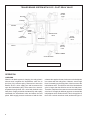
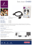
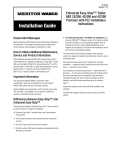
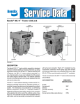
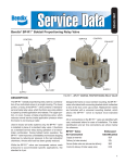
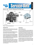
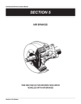
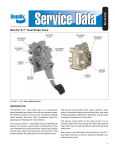
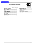
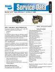
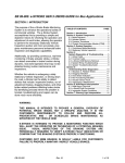
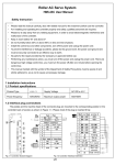
SD-03-1063
®
Bendix® R-12P™ Pilot Relay Valve
RESERVE
SPRING
LOAD
PISTON
RELAY
PISTON
1/4” CONTROL
1/4” CONTROL
COVER
EQUALIZING
ORIFICE
BODY
3/8”
DELIVERY
1/2”
SUPPLY
1/2” SUPPLY (2)
3/8” DELIVERY (4)
INLET/EXHAUST
VALVE
EXHAUST
FIGURE 1 - CUTAWAY AND EXTERNAL VIEW
DESCRIPTION
The Bendix® R-12P™ pilot relay valve is designed to speed
up control signal application and release on long non-towing
trailers, towing trailers, dollies, and long wheelbase tractors.
It does this without adversely affecting the control signal.
The R-12P™ valve replaces the current R-8P™ valve.
Unlike a standard relay valve used as a “booster,” which
typically has a 2-4 psi differential between control and
delivery, the R-12P™ valve has zero differential. It “speeds”
up control line signal application and release in a train
of vehicles, and it delivers the same air pressure that it
receives. This provides a uniform brake signal to all trailer
and dolly brakes, even during light applications.
The unique R-12P™ valve feature is that it uses a supply
air pressure load to quicken the valve’s response time. By
balancing the pressure signal to all trailer and dolly brakes,
the R-12P™ valve aids in achieving overall vehicle brake
pressure balance, timing balance, and stability.
It also substantially improves brake lining wear balance
on combination vehicles by making even the most distant
brake contribute its share of braking effort.
Figure 2 shows the R-12P™ valve in a trailer air brake
schematic. Note that additional air lines for a towing trailer
are shown as dashed lines.
The R-12P™ valve uses the Bendix® R-1® valve family lower
body and standard Bendix mounting brackets. It can also
be reservoir-mounted.
The body and cover are die-cast aluminum, and the valve’s
weight is approximately 2.3 lbs. Porting is as follows:
Supply (SUP)
Delivery (DEL)
Control (CON)
Exhaust (EXH)
Qty.
2
4
1
1
Size
1/2”
3/8”
1/4”
--
1
TRAILER BRAKE SYSTEM WITH R-12P™ PILOT RELAY VALVE
VENTED
CUT-OUT
COCK
DELIVERY
CONTROL
CONTROL
R-12P™
VALVE
SUPPLY
SINGLE
CHECK VALVE
SPRING
BRAKE
VALVE
SERVICE RELAY
VALVE
QUICK
RELEASE
VALVE
RESERVOIR
SUPPLY
VENTED
CUT-OUT
COCK
BRAKE CHAMBER
SLACK ADJUSTER
-- -- -- -- -- ADDITIONAL PLUMBING FOR TOWING TRAILER
FIGURE 2 - TYPICAL R-12P™ PILOT RELAY VALVE SYSTEM SCHEMATIC
OPERATION
CHARGING
When the air brake system is charging, the relay piston’s
exhaust seat is against the inlet/exhaust valve due to
the force of the reserve spring. Reservoir air enters the
Bendix® R-12P™ valve supply port and becomes active
upon the inlet/exhaust valve. At the same time, reservoir
air passes through the R-12P™ valve body channel to the
load piston. Supply air builds simultaneously and equally
underneath the inlet/exhaust valve and above the load
piston. While supply pressure continues to hold the inlet/
2
exhaust valve against its seat, it also moves the load piston
into contact with the relay piston. However, even though
force is increasing on the relay piston, it does not move the
inlet/exhaust valve. The effective area of the inlet/exhaust
valve is larger than the effective area of the load piston.
Therefore, load piston force cannot overcome inlet/exhaust
valve force. So supply air builds to governor cut-out and the
inlet/exhaust valve remains closed. This is the position of
the R-12P™ valve in normal run mode, as shown in Figure 3.
CONTROL
PORT
LOAD PISTON
RELAY PISTON
Note that these events occur quickly, due to the “preload”
on the relay piston. This preload, provided by supply air
pressure acting on the load piston, is a feature unique to
the R-12P™ valve.
BALANCE
SUPPLY PORT
DELIVERY
PORT
INLET/EXHAUST
VALVE
FIGURE 3 - CHARGING
Air pressure being delivered by the open inlet valve is
also effective underneath the R-12P™ valve relay piston.
When air pressure beneath the piston approaches control
pressure on top of the piston, the piston and inlet valve lift
together and close the inlet valve. The exhaust remains
closed, and the valve achieves “force balance.” That is,
the piston and inlet/exhaust valve are in their neutral
state. This is the position commonly known as “balanced”
when referring to conventional relay valves. However,
conventional relay valves cannot achieve true air pressure
balance because of their inherent differentials. The R-12P™
valve achieves this balance because of its equalizing
orifice. The orifice allows control pressure and delivery
pressure to be “common” and equalize. In this position,
shown in Figure 5, sustained service brake applications
can be held, with no “residual” differential.
CONTROL
PORT
LOAD PISTON
RELAY PISTON
EQUALIZING
ORIFICE
PROVIDES AIR
PRESSURE
BALANCE
LOAD PISTON
RELAY
PISTON
CONTROL PORT
SUPPLY PORT
INLET/EXHAUST
VALVE
FIGURE 4 - NORMAL (RAPID) APPLICATION
NORMAL (RAPID) APPLICATION
®
™
Figure 4 shows a Bendix R-12P valve receiving a
“normal” service brake application. “Normal” means the
control signal is applied rapidly enough to build up pressure
on the relay piston and “open” the inlet valve, causing the
R-12P™ valve to react like a relay valve. The relay piston
opens the inlet, allowing supply air to flow out the delivery
port to the next valve in the system.
SUPPLY PORT
INLET/EXHAUST
VALVE
DELIVERY
PORT
FIGURE 5 - BALANCE
3
LOAD PISTON
CONTROL PORT
RELAY PISTON
LOAD PISTON
CONTROL PORT
RELAY PISTON
SUPPLY PORT
INLET/EXHAUST
VALVE
DELIVERY PORT
EXHAUST
SUPPLY PORT
DELIVERY PORT
INLET/EXHAUST
VALVE
FIGURE 6 - RAPID EXHAUST
FIGURE 7 - EQUALIZING (SLOW) APPLICATION
RAPID EXHAUST
If, during the light brake application, the driver modulates
the treadle slowly, and not enough to open the R-12P™ inlet
valve, the desired control pressure will still pass on to the
next valve, maintaining zero differential.
Figure 6 shows a rapid service brake release. Air above
the relay piston travels back out the control port to be
exhausted. With the lack of air pressure above the
piston, air pressure below lifts the piston, closing the inlet
and opening the exhaust. Delivery air then exhausts to
atmosphere.
EQUALIZING (SLOW) APPLICATION
When a control signal enters the Bendix® R-12P™ valve,
it acts on the relay piston. However, Figure 7 shows the
control signal passing through the valve without causing
piston movement. The air is passing through the relay
piston’s equalizing orifice, directly through the valve and
out the delivery port to the next valve in the air system.
This situation occurs if air pressure build-up is slow and
the pressure above the relay piston is not strong enough
to open the valve. (Air pressure above the piston must be
at least 3 psi greater than air pressure below the piston to
cause movement.)
In the equalizing application, even though the inlet valve
does not open, the control signal is not decreased because
the equalizing orifice allows it to pass directly through the
R-12P™ valve. Note that this condition exists during very
slow service brake applications.
For example, if a vehicle is traveling over a long downhill
grade, the driver may want to limit speed and maintain
vehicle control through proper gearing, engine speed and
a light service brake application.
4
LOAD PISTON
CONTROL PORT
RELAY PISTON
SUPPLY PORT
INLET/EXHAUST
VALVE
DELIVERY PORT
FIGURE 8 - EQUALIZING (SLOW) EXHAUST
EQUALIZING (SLOW) EXHAUST (SEE FIGURE 8)
As described earlier, the result of any service brake
application with a Bendix® R-12P™ valve is air pressure
balance above and below the relay piston. If the brake
valve is modulated slowly upon release so that pressure
beneath the piston is not great enough to open the exhaust,
delivery air will pass through the equalizing orifice and out
the control port to be exhausted.
LOAD PISTON
RESERVE SPRING
SEALS EXHAUST
RELAY PISTON
CONTROL
PORT
REDUCTION OF SUPPLY PRESSURE
Figure 9 shows the R-12P™ valve with no supply pressure.
With no supply air, the reserve spring is strong enough
to hold the relay piston on the exhaust seat, but it is not
strong enough to overcome the force of the inlet/exhaust
valve spring. So both inlet and exhaust valves are closed.
SUPPLY PORT
Service Brake Applications with Reduced Supply
Pressure
Rapid Application - Use of Supply Line Single Check
Valve
If a rapid service brake application is made, control air
moves the relay piston and opens the inlet valve; but there
is no supply air to deliver. Control air then travels into the
supply port. The single check valve in the R-12P™ valve
supply port (shown in Figure 2) prevents this air from
escaping to atmosphere through the open or damaged
supply source. Control air also passes through the
equalizing orifice and out the delivery port, assuring no
reduction or loss of control signal to subsequent vehicles.
Equalizing (Slow) Application
If an equalizing (slow) service brake application is made
with reduced supply air pressure, control air passes
through the equalizing orifice and out the delivery port to
subsequent vehicles in the train.
Control air cannot escape to atmosphere because the
reserve spring keeps the exhaust closed.
PREVENTIVE MAINTENANCE
Important: Review the Bendix Warranty Policy before
performing any intrusive maintenance procedures. A
warranty may be voided if intrusive maintenance is
performed during the warranty period.
No two vehicles operate under identical conditions, as a
result, maintenance intervals may vary. Experience is a
valuable guide in determining the best maintenance interval
for air brake system components. At a minimum, the valve
should be inspected every 6 months or 1500 operating
hours, whichever comes first, for proper operation. Should
the valve not meet the elements of the operational tests
noted in this document, further investigation and service
of the valve may be required.
INLET/EXHAUST
VALVE
DELIVERY PORT
FIGURE 9 - REDUCTION OF SUPPLY PRESSURE
SERVICE CHECKS
1. Remove any accumulated contaminants. Visually
inspect the valve’s exterior for excessive corrosion
or physical damage. Repair/replace the valve as
necessary.
2. Inspect all air lines connected to the valve for signs
of wear or physical damage. Repair/replace as
necessary.
3. Test air line fittings for excessive leakage and tighten
or replace as necessary.
OPERATIONAL AND LEAKAGE TESTS
1. Block the vehicle’s wheels and fully charge the air
system.
2. Apply and release the service brakes several times
and check for prompt response of the brakes at all
appropriate wheels.
3. With the air system fully charged, apply a soap solution
to the R-12P™ valve exhaust port. Leakage of a 1”
bubble in 5 seconds is permissible.
4. Make and hold a full brake application and again apply
a soap solution to the R-12P™ valve exhaust. Leakage
of a 1” bubble in 3 seconds is permissible.
5. With the brakes still applied, apply a soap solution
around the valve where the cover meets the body. No
leakage at this point is permitted.
If the valve does not function as described; or if leakage is
excessive, repair the valve or replace it at any authorized
parts outlet.
5
NOTE: If a supply line single check valve is present (see
Figure 2), check it for leakage. Disconnect the inlet
side of the single check valve and coat the open
end with a soap solution. Make and hold a full
brake application. Leakage of a one inch bubble in
five seconds is permissible. If the valve’s leakage
is excessive, replace it with a 1/2” single check
valve.
REMOVAL
1. Drain all system air pressure.
2. Identify and mark or label all air lines and their
connections to the Bendix® R-12P™ valve and the single
check valve, if present. Then disconnect the air lines.
3. Remove the R-12P™ valve from the vehicle.
6
INSTALLATION
1. Use the mounting bracket provided, or, if securing the
valve to a reservoir, use a Schedule 80 (heavy wall)
short couple pipe nipple.
2. Reconnect all air lines to the valve using the
identification made during removal. Be sure to use pipe
thread sealant.
3. Test all air fittings for excessive leakage and tighten as
needed. Also, perform OPERATIONAL AND LEAKAGE
TESTS before placing the vehicle back into service.
COVER
FASTENER
LOAD
PISTON
3
RELAY PISTON
4
5
1
2
RESERVE
SPRING
BODY
12
11
10
9
8
7
6
FIGURE 10 - EXPLODED VIEW
DISASSEMBLY
The following procedure is for reference only. Always
have the appropriate maintenance kit on hand, and use
its instructions in lieu of those presented here. Refer to
Figure 10 throughout.
CAUTION: The Bendix® R-12P™ valve may be lightly
clamped in a bench vise during disassembly.
However, overclamping will cause damage
to the valve and result in leakage and/or
malfunction. If a vise is used, position the
valve so the jaws bear on the supply ports on
opposing sides of the valve’s body.
1. Remove the four fasteners that secure the cover to the
body. Then slowly remove the cover.
2. Remove and discard the small o-ring (1) that seals the
internal channel and the large o-ring (2) between the
cover and the body.
3. Remove the load piston from the cover. Note: If
necessary, use approximately 20 psi of shop air,
directed into the load piston’s air passage in the cover,
to dislodge it. CAUTION: The piston will leave the cover
with some force.
4. Remove and discard the load piston’s o-ring (3).
5. Remove the reserve spring and the relay piston from
the body. Remove and discard the relay piston’s o-rings
(4) and (5).
6. While holding exhaust cover (7), remove and discard
the snap ring (6) that secures the cover to the body.
7. Remove and discard exhaust cover (7) and its o-rings
(8) and (9).
8. Remove and discard valve spring (10), valve retainer
(11), and inlet/exhaust valve (12) from the body.
CLEANING & INSPECTION
1. Using mineral spirits or an equivalent solvent, clean and
thoroughly dry all metal parts. Do not damage bores
with metal tools.
2. Wash all non-metallic components in a soap and water
solution. Dry thoroughly.
3. Inspect interior and exterior of all metal parts for severe
corrosion, pitting, and cracks. Superficial corrosion
and/or pitting on the exterior of the body and cover
is acceptable. Replace the entire valve if the body or
cover interior show signs of corrosion or pitting.
4. After washing, inspect relay piston for cracks, wear,
or distortion. Replace the valve if these conditions are
found.
7
5. Make certain the air channel running from the cover
through the top surface of the body to the supply port
is clear and free of obstruction.
6. Inspect the pipe threads in the body. Make certain they
are clean and free of thread sealant.
7. Inspect all air line fittings for corrosion. Replace as
necessary. Remove all old thread sealant before
reuse.
ASSEMBLY
1. Before assembly, lubricate all o-rings, seals, and pistons
as well as body and cover bores, using the lubricant
provided in the maintenance kit. Use all of the lubricant,
and spread it evenly on all rubbing surfaces.
2. Install valve retainer (11) on inlet/exhaust valve (12)
so that the flange of the retainer surrounds the rubber
portion of the valve.
3. Install inlet/exhaust valve (12) in the body.
4. Install valve spring (10) over the inlet/exhaust valve in
the body.
8
5. Install large and small diameter o-rings (8) and (9) in
exhaust cover (7).
6. Place the exhaust cover on the inlet/exhaust valve
spring. Then depress the cover against the spring’s
force into the body. Secure the cover with the snap
ring (6).
7. Install o-rings (4) and (5) onto the relay piston. Then
place the reserve spring in the piston and install the
piston into the body.
8. Install the load piston’s o-ring (3) onto the load piston.
Then install the load piston into the cover, small end
first.
9. Install small o-ring (1) that seals the internal channel
and large o-ring (2) onto the cover.
10. Place the cover on the body and secure with its four
fasteners. Torque to 120 - 150 in. lbs.
11. Perform OPERATIONAL AND LEAKAGE TESTS before
returning the vehicle to service.
BW1711 © 2011 Bendix Commercial Vehicle Systems LLC. All rights reserved. 4/2011 Printed in U.S.A.