1
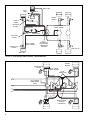
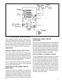
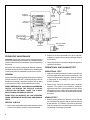
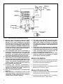
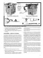
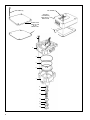
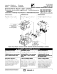
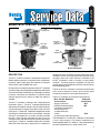
SD-13-4772
®
Bendix® M-12™ & M-12R™ AntiLock Modulator
4 PIN
CONNECTOR
SUPPLY
PORT
DELIVERY
PORTS
2 VERTICAL
2 HORIZONTAL
CONTROL
PORT
COVER
PLATE
DELIVERY
PORTS
4 VERTICAL
SUPPLY
PORT
WIRE
HARNESS
CONTROL
PORT
3 PIN
CONNECTOR
M-12™ Modulator
M-12R™ Modulator
FIGURE 1 M-12™ AND M-12R™ MODULATORS
DESCRIPTION
The M-12™ antilock modulator is a standard component in
Bendix antilock systems. It is comprised of two components:
solenoids, which rapidly apply and exhaust air during an
antilock stop, and a standard relay valve.
During normal, non-antilock operation, the M-12™ modulator
serves as a relay valve that speeds the application and release
of the service brakes. If wheel lock up is impending, a antilock
controller commands the solenoids to modulate brake
chamber pressure on the axle(s) on which the system is
installed.
The M-12™ modulator is offered in two configurations as
illustrated in figure 1. The M-12™ modulator permits direct
attachment of an antilock controller, and it accepts electronic
commands from the controller through a four pin connector
(see Figure 1). The M-12R™ modulator is designed for remote
mounting on a vehicle frame rail or cross member. It accepts
electronic commands from a remote mounted controller
through a wire harness assembly that has a four pin
connector at one end and a three pin connector at the other
(see Figure 1). The M-12™ modulator and M-12R™ modulator
differ from each other only in that the M-12™ modulator is
designed for direct controller mounting while the M-12R™
modulator uses a cover plate where the controller would
normally mount and a wire harness is attached to the
M-12R™ modulator in order to connect it to the antilock
controller. Two body styles are available; one with four
vertical delivery ports and another with two vertical and two
horizontal delivery ports.
The M-12™/M-12R™ modulator is normally mounted close
to the service actuators it serves, and it can be nipple
mounted to a reservoir or secured to the frame rail.
The M-12™ modulator air connections are as follows:
M-12™/M-12R™ Modulator
Air Connection
Supply (to reservoir)
Delivery (to brake actuator)
(can have 2 horizontal & 2
vertical deliveries or
4 vertical deliveries)
Control
(to rear service brake valve delivery)
Embossed
Identification
SUP
DEL
CON
The standard M-12™ and M-12R™ modulator is offered with
a 4 psi crack pressure. The internal components are
interchangeable with R-12™ and R-14™ relay valves therefore,
the same maintenance kit is used to service all.
1
SERIAL LINK
DASH
LAMP
RELAY
SPRING
BRAKES
SERVICE
BRAKE
RETARDER
DISABLE
IN-AXLE WHEEL
SPEED SENSOR
M-21™/M-22™
MODULATOR
BRAKE VALVE
STOP LIGHT
SWITCH
WS-20™ WHEEL
SPEED SENSOR
NOTCHED HUB
EXCITER
M-12™
MODULATOR
WITH ANTILOCK
CONTROLLER
MOUNTED
REAR AXLE (S)
FRONT AXLE
FIGURE 2A FULL VEHICLE AXLE CONTROL - TRUCK/TRACTOR
NOTCHED HUB
EXCITER
SPRING
BRAKES
WS-20™ WHEEL
SPEED SENSOR
M-12R™
MODULATOR
SR-5™ TRAILER
SPRING BRAKE
VALVE
REMOTE MOUNT
ANTILOCK
CONTROLLER
FIGURE 2B TANDEM SPREAD AXLE TRAILER - AXLE CONTROL SYSTEM
2
DOUBLE
CHECK
TRAILER
CONTROL
EXHAUST
SOLENOID
BRAKE
VALVE
CONTROL
SUPPLY
SOLENOID
PISTON
RESERVOIR
DELIVERY
SUPPLY
EXHAUST
SERVICE BRAKE
CHAMBER
FIGURE 3 APPLYING: NORMAL SERVICE APPLICATION
Figure 2 shows two antilock systems in which the M-12™
and M-12R™ modulator can be used. Figure 2A is a typical
schematic for a full vehicle axle control system, and Figure
2B is a typical trailer installation using the M-12R ™
modulator. With the attachment of different controllers, the
M-12™ or M-12R™ modulator can adapt to either system.
OPERATION
APPLYING: NORMAL SERVICE APPLICATION
When a normal service brake application is made, and the
antilock wheel sensors do not sense impending wheel lock
up, service air pressure enters the modulator control port.
Air passes through the normally-open supply solenoid and
into the relay valve portion of the modulator. (The normallyclosed exhaust solenoid remains closed.)
Air acts on the relay piston closing the exhaust and opening
the inlet. Supply air pressure flows to the delivery ports and
out to the service brake chambers.
BALANCED POSITION: NORMAL SERVICE
APPLICATION
The relay valve portion of the modulator reaches a balanced
position when service delivery pressure acting on the
underside of the relay piston approaches that of the control
air acting on the top side of the piston. The piston moves
allowing the inlet valve to close, while the exhaust remains
closed. This prevents the valve from delivering or exhausting
air.
EXHAUSTING: NORMAL SERVICE
APPLICATION
When a service application is released, air at the modulator
control port returns to the application valve. Control pressure
above the relay piston exhausts through the supply solenoid
and the check valve in the solenoid housing out to the exhaust
port of the valve that sent the control signal. Relay piston
movement opens the modulator's exhaust, allowing air from
the piston's underside (and from the service brake chambers)
to exhaust through the modulator exhaust port.
ANTILOCK MODE: SOLENOIDS ACTIVATED
If a service application is made and the antilock controller
senses impending wheel lockup, it commands the M-12™/
M-12R™ modulator to modify the service brake application
pressure. When activated by the controller, the M-12™/
M-12R™ modulator solenoids alter application by exhausting
and applying control air pressure above the relay piston.
The supply solenoid closes, preventing control line pressure
from entering the modulator. Then the exhaust solenoid
opens, allowing control pressure to exhaust from the top
side of the piston through the exhaust port of the solenoid
assembly. This activity occurs in a pulsating manner,
simulating "pumping the brakes."
3
DOUBLE
CHECK
EXHAUST
SOLENOID
TRAILER
CONTROL
BRAKE
VALVE
CONTROL
SUPPLY
SOLENOID
PISTON
RESERVOIR
DELIVERY
SUPPLY
EXHAUST
SERVICE BRAKE
CHAMBER
FIGURE 4 BALANCED POSITION
PREVENTIVE MAINTENANCE
Important: Review the warranty policy before performing
any intrusive maintenance procedures. An extended warranty
may be voided if intrusive maintenance is performed during
this period.
2. Inspect all air lines connected to the M-12™/M-12R™
modulator for signs of wear or physical damage. Replace
as necessary.
3. Test air line fittings for excessive leakage and tighten or
replace as necessary.
Because no two vehicles operate under identical conditions,
maintenance intervals will vary. Experience is a valuable guide
in determining the best maintenance interval for a vehicle.
OPERATIONAL AND LEAKAGE TEST
GENERAL
1. Apply and release the brakes several times and check
for prompt application and release at each wheel. If the
response at the wheels is "sluggish," check for a kinked
or obstructed air line leading to or from the M-12™/
M-12R™ modulator.
Perform the following tests and inspections at the prescribed
intervals. If the M-12™/M-12R™ modulator fails to function as
described, or if leakage is excessive, repair the valve or obtain
a replacement from any authorized Bendix parts outlet.
EVERY THREE MONTHS, 25,000 MILES, 900 OPERATING
HOURS, OR DURING THE VEHICLE CHASSIS
LUBRICATION INTERVAL, MAKE THE VISUAL
INSPECTIONS IN THE SERVICE CHECKS
EVERY YEAR, 100,000 MILES, OR 3,600 OPERATING
HOURS, PERFORM THE OPERATIONAL AND LEAKAGE
TESTS
SERVICE CHECKS
1. Remove any contaminants and visually inspect the valve's
exterior for excessive corrosion or physical damage.
4
OPERATIONAL TEST
2. Road test the vehicle to determine proper modulator
operation. The system can be tested by making an
aggressive stop from a vehicle speed of 20 mph. When
an aggressive stop is made, solenoid pulsation creates
an audible burst of air, which can be heard from outside
the vehicle.
LEAKAGE TEST
1. Build air system pressure to governor cut out. With the
service brakes fully applied, coat the exhaust port with
a soap solution. A 1" bubble in 3 seconds is permitted.
Coat the outside of the modulator body to check for seal
ring leakage. No leakage is permitted.
DOUBLE
CHECK
TRAILER
CONTROL
EXHAUST
SOLENOID
BRAKE
VALVE
CONTROL
SUPPLY
SOLENOID
PISTON
RESERVOIR
DELIVERY
SUPPLY
SERVICE BRAKE
CHAMBER
EXHAUST
FIGURE 6 ANTILOCK MODE: SOLENOIDS ACTIVATED
2. With the service brakes released, coat the exhaust port
and the area around the retaining ring with a soap solution.
A 1" bubble in 3 seconds is permitted.
3. If leakage is excessive around the supply and exhaust
solenoids, replace the M-12™/M-12R™ modulator. If
excessive leakage is detected where the solenoid
assembly and body meet, replace the M-12™/M-12R™
modulator. If excessive leakage is detected at the exhaust
port, before replacing the M-12™/M-12R™ modulator,
perform the following test. Place the vehicle in park by
exhausting the air pressure from the emergency side of
the spring brake. Perform the leakage check.
ELECTRICAL TESTS
1. Before testing the solenoid assembly of a "suspect"
modulator, its location on the vehicle should be confirmed
using the Trouble Shooting or Start-Up procedure for the
specific antilock controller in use. (See the Service Data
Sheet for the antilock controller for this procedure.)
2. Proceed to the modulator in question and identify it as
an M-12™ or M-12R™ modulator and inspect its wiring
connector. In the case of an M-12™ modulator it will be
necessary to remove the four cap screws that secure
the controller to the modulator. The M-12R™ modulator
has an external connector that can be tested without
removing the cover. Disconnect the connector and test
the resistance between the pins on the modulator. Refer
to figure 7.
For the FOUR pin connector test as follows
A.
Black to Black: Read 9 to 12 OHMS
B.
White to White: Read 9 to 12 OHMS
For the THREE pin connector on the M-12R test as
follows
A.
Red to Black:
Read 9 to 12 OHMS
B.
Red to White:
Read 9 to 12 OHMS
Note: If the resistance readings for the three pin connector
are NOT as shown, the wire harness leading to the to
the under side of the modulator cover may require repair
or replacement. Remove the cover (as discussed
elsewhere in this manual) and disconnect the four pin
connector and perform the tests shown for the FOUR
pin connector. If the resistance is correct at the four pin
connector the short wire harness between the four and
three pin connectors is at fault.
3. If the resistance values are NOT AS SHOWN, replace
the modulator.
WARNING! PLEASE READ AND FOLLOW
THESE INSTRUCTIONS TO AVOID
PERSONAL INJURY OR DEATH:
When working on or around a vehicle, the following
general precautions should be observed at all times.
1. Park the vehicle on a level surface, apply the
parking brakes, and always block the wheels.
Always wear safety glasses.
5
DOUBLE
CHECK
EXHAUST
SOLENOID
TRAILER
CONTROL
BRAKE
VALVE
CONTROL
SUPPLY
SOLENOID
PISTON
RESERVOIR
DELIVERY
SUPPLY
EXHAUST
SERVICE BRAKE
CHAMBER
FIGURE 6 ANTILOCK MODE: SOLENOIDS ACTIVATED
2. Stop the engine and remove ignition key when
working under or around the vehicle. When
working in the engine compartment, the engine
should be shut off and the ignition key should be
removed. Where circumstances require that the
engine be in operation, EXTREME CAUTION should
be used to prevent personal injury resulting from
contact with moving, rotating, leaking, heated or
electrically charged components.
3. Do not attempt to install, remove, disassemble or
assemble a component until you have read and
thoroughly understand the recommended
procedures. Use only the proper tools and observe
all precautions pertaining to use of those tools.
4. If the work is being performed on the vehicle’s air
brake system, or any auxiliary pressurized air
systems, make certain to drain the air pressure from
all reservoirs before beginning ANY work on the
vehicle. If the vehicle is equipped with an AD-IS™
air dryer system or a dryer reservoir module, be
sure to drain the purge reservoir.
5. Following
the
vehicle
manufacturer’s
recommended procedures, deactivate the electrical
system in a manner that safely removes all
electrical power from the vehicle.
6. Never exceed manufacturer’s recommended
pressures.
7. Never connect or disconnect a hose or line
containing pressure; it may whip. Never remove a
component or plug unless you are certain all
system pressure has been depleted.
6
8. Use only genuine Bendix ® replacement parts,
components and kits. Replacement hardware,
tubing, hose, fittings, etc. must be of equivalent
size, type and strength as original equipment and
be designed specifically for such applications and
systems.
9. Components with stripped threads or damaged
parts should be replaced rather than repaired. Do
not attempt repairs requiring machining or welding
unless specifically stated and approved by the
vehicle and component manufacturer.
10. Prior to returning the vehicle to service, make
certain all components and systems are restored
to their proper operating condition.
MODULATOR REMOVAL
1. Identify, mark, or label all air lines and wiring cables and
their respective connections on the modulator (M-12R™)
or modulator/controller assembly (M-12™).
2. Disconnect all air lines and wiring.
3. Remove the modulator (M-12R™) or modulator/controller
assembly (M-12™) from the vehicle.
MODULATOR INSTALLATION
1. Install all air line fittings and plugs. Make certain no thread
sealing material enters the modulator.
2. Install the assembled modulator (M-12R™) or modulator/
controller assembly (M-12™) on the vehicle.
FOUR PIN
CONNECTOR
SHORT WIRE
HARNESS
BETWEEN THREE
AND FOUR PIN
CONNECTOR
(M-12R™
MODULATOR
ONLY)
THREE PIN
CONNECTOR
TYPICAL M-12™ MODULATOR
TYPICAL M-12R™ MODULATOR
EXHAUST
HOLD
Black
White
WHITE
BLACK
COMMON
SHORT WIRE HARNESS USED ON THE M-12R™ MODULATOR
FIGURE 7 M-12™/M-12R™ MODULATOR CONNECTORS & WIRE HARNESS
3. Reconnect all air lines and wiring cables to the modulator
or modulator/controller assembly using the identification
made in MODULATOR REMOVAL, step 1.
4. Test all air fittings for excessive leakage and tighten as
necessary.
DISASSEMBLY - REFER TO FIGURE 8
The following disassembly and assembly procedure is
presented for reference purposes only. A complete
disassembly and assembly is described in detail, and it is
assumed that the appropriate maintenance kit(s) is on hand.
Several replacement parts and maintenance kits are
available which do not require full disassembly. The
instructions provided with these parts and kits should be
followed in place of the instructions presented here.
CAUTION: The M-12™/M-12R™ may be lightly clamped in a
bench vise during disassembly. However, over clamping will
result in damage, leakage, and/or malfunction. If a vise is to
be used, position the M-12™/M-12R™ so the jaws bear on
the flat area of the supply port and its opposing side of the
body.
1. Remove all air fittings and plugs from the valve.
2. Mark the relationship of the electronic controller and
solenoid assembly to the body.
Note: Only the M-12™ modulator will have a controller
installed directly on the solenoid assembly. The M-12R™
modulator will only have a cover plate enclosing the
solenoid assembly.
If a mounting bracket was used, mark the position of the
bracket on the unit.
3. Remove and retain the four cap screws that hold the
controller (M-12™ modulator) or cover plate (M-12R™
modulator) to the solenoid assembly. Then carefully lift
the controller or cover plate from the solenoid
assembly(3). The controller will be attached to the
modulator by a four pin connector. Press the lock tab on
the side of the connector and pull the connector from its
socket in the controller. Now separate the controller or
cover plate from the modulator. Remove the gasket(1)
that seals the controller or cover plate to the solenoid
assembly(3).
Remove the four cap screws(2) that secure the solenoid
assembly(3) to the valve body(7). Separate the solenoid
assembly from the valve body, and remove sealing ring(4)
from the protrusion on the bottom of the solenoid
assembly.
4. Remove retaining ring(14), then remove the exhaust
assembly(13). Remove o-ring(11) and o-ring(12) from the
O.D. and l.D., respectively, of the exhaust assembly(13).
5. Remove spring(10) and inlet/exhaust assembly(8).
Remove the spring seat(9) from the inlet exhaust
assembly.
7
CAP SCREW (4)
CAP SCREW (4)
ANTILOCK
CONTROLLER
USED ON M-12™
MODULATOR
COVER PLATE
USED ON THE
M-12R™
MODULATOR
1
1
2
3
4
5
6
7
8
9
10
11
12
13
14
FIGURE 8 M-12™/M-12R™ MODULATOR COMPONENTS
8
6. Using thumb force on the piston stem, push the piston(6)
out the opposite end of the body(7). Remove o-ring(5)
from the piston.
5. Depress the exhaust assembly into the bore until it
exposes the groove for snap ring(14). Install snap ring(14)
into its groove. Make sure it is fully seated.
7. Discard all items that have replacement parts in the
maintenance kit.
6. Install o-ring(5) into its groove in piston(6). Install piston(6)
into the M-12 body. The piston stem fits into the small
hole in the center of the body.
CLEANING & INSPECTION
1. Using mineral spirits or an equivalent solvent, clean and
thoroughly dry all parts. Do not allow mineral spirits to
come into contact with the wiring connectors or
solenoids.
2. Inspect the interior and exterior of all parts that will be
reused for severe corrosion, pitting or cracks. Superficial
corrosion and/or pitting on the exterior portion of the body
is acceptable.
3. Inspect bores for deep scuffing or gouges.
4. Inspect pipe threads in the body. Make certain they are
clean and free of thread sealant.
5. Inspect all air line fittings and plugs for corrosion. Clean
all old thread sealant from pipe threads.
6. Any component exhibiting a condition described in
inspection steps 2 to 5 should be discarded and replaced
before proceeding.
ASSEMBLY - REFER TO FIGURE 8
1. Using a lubricant (Bendix Pc. No. 291126) lightly coat
all o-rings, seals, pistons, and body bores.
2. Install spring seat(9) onto inlet exhaust valve(8) so that
it covers the rubber seat of the inlet exhaust valve. Place
inlet/exhaust valve, large diameter first, into the body(7)
bore.
3. Install spring(10) over the barrel of the inlet exhaust
valve(8) so that one end of the spring rests on the spring
seat(9).
7. Install o-ring(4) onto the protrusion on the bottom of the
solenoid assembly(3). Install the solenoid assembly(3)
onto the body(7). The solenoid assembly will fit on the
body(7) in any of four orientations, 90 degrees apart
however it should be installed in the position marked in
step 2 of the Disassembly instructions. Secure the
solenoid assembly to the body with the four cap
screws(2). Torque to 120 to 150 in. lbs.
8. Install gasket(1) onto the controller or cover plate.
A. If installing a controller, connect the four pin connector on the solenoid assembly(3) to the corresponding
connector on the controller making certain the connector halves snap and lock.
B. If installing a cover plate, make certain the “pinch”
grommet on the short wire harness is in one of the
two “notches” in the solenoid assembly(3) so that
when the cover plate is installed the wire harness
will not be pinched.
Note the relationship mark made in step 2 of the
disassembly, then secure the controller or cover plate
to the solenoid assembly(3) using the four cap screws.
Torque to 30 60 in. lbs.
9. Install all air line fittings and plugs. Make certain no thread
sealing material enters the valve.
10. Install the antilock assembly on the vehicle. Perform the
"OPERATIONAL AND LEAKAGE TESTS" before
returning the vehicle to service.
4. Install o-rings(11 and 12) into the respective grooves of
the outside and inside diameter of the exhaust
assembly(13). Place the large diameter of the exhaust
assembly against the spring(10) and compress the spring
until the exhaust assembly enters the bore of the body(7)
and o-ring(11) seals against the wall of the bore. Make
certain not to cut or pinch the o-ring.
9
10
11
12
BW1669 © 2004 Bendix Commercial Vehicle Systems LLC. All rights reserved. 4/2004 Printed in U.S.A.