1
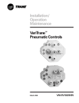
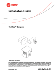
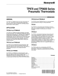
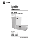
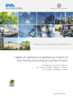
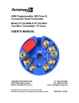
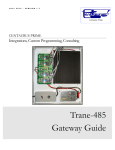
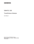
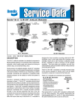
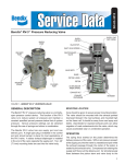
Installation/ Operation Maintenance VariTrane™ Pneumatic Controls March 2002 VAV-SVX02B-EN Thermostat Thermostat Selection and Location Figure 1–Two-Pipe Remote Thermostat (Reverse-Acting) In general, both one- and two-pipe thermostats have a gain of 2.5 psi per degree Fahrenheit, unless special thermostats are used that provide a different gain. The major difference between them is that a one-pipe thermostat is considered a lowcapacity thermostat and a two-pipe thermostat is considered a highcapacity thermostat. When selecting between one-pipe and two-pipe thermostats consider the following: Tee Two-Pipe Remote-Mounted T-Stat (Reverse-Acting) S Use one-pipe thermostat when: tubing runs are less than 50 feet from thermostat to controller. a single thermostat will control no more than three controllers. slower response is desired from the thermostat. Use two-pipe thermostat when: tubing runs exceed 50 feet from thermostat to controller. a single thermostat will control four or more controllers. high capacity air is required due to restrictions in the air line. Thermostat Piping The two-pipe thermostat (Figure 1) includes a restrictor (internally). Attach supply air line and output pressure (branch) line to the thermostat. The one-pipe thermostat (Figure 2) requires an external restrictor tee. Connect main air supply to restricted leg of restrictor tee. Connect branch line from restrictor tee to the thermostat. 2 15 .4) 103 ( 20 .9) 137 ( Figure 2–Typical One-Pipe Thermostat (Reverse-Acting) Tee Restrictor Tee One-Pipe Remote-Mounted T-Stat (Reverse-Acting) Restricted Leg Fan P.E. Switch–1 (N.O.) S 20 (137.9) 9 PSI (62.06 kPa) VAV-SVX02B-EN Thermostat Throttling Range: 2–10°F (1–5°C) Gain: 2.5 psi/°F Adjustable Operation Pneumatic thermostats modulate output air pressure in response to room air temperature. Pneumatic thermostats fall into two categories: directacting or reverse-acting.This section describes how thermostat output pressure responds to changes in room temperature. Figure 3 graphically illustrates the relationship between room temperature and output pressure of a direct-acting thermostat.The graph in Figure 3 shows that as the room temperature increases, so does the output pressure of the thermostat. Figure 3–Direct-Acting Thermostat Response Figure 4 illustrates the pressure/ temperature characteristics for a reverse-acting thermostat. As room temperature increases, the thermostat output pressure decreases. Figure 4–Reverse-Acting Thermostat Response Output Pressure Specifications TP970 Series PneumaticT-stats Maximum Safe Air Pressure: 25psi (172 kPa) Maximum Safe AirTemperature: 150°F (66°C) Input Temperature Output Pressure A thermostat in proper working order will be able to output a pressure ranging from approximately .5 psi to supply air pressure depending on distance from indicated setpoint. Input Temperature VAV-SVX02B-EN 3 Reversing Relay Installation and Operation The reversing relay is a proportional, non-bleeding device for use in pneumatic control systems where a proportional signal from a controlling device must be reversed (see Figure 5).The most common use of the reversing relay is to change the action of a pneumatic thermostat. Figure 5–Pneumatic Reversing Relay Trane Part No. RLY-755 Figure 6–Reversing Relay Connections Output Branch S 20 (137.9) 9 PSI In (62.06 kPa) B Reversing Relay M 9 PSI Out (62.06 kPa) S Input Branch Inc. Figure 7–Reversing Relay Characteristics Output Branch Pressure The reversing relay requires three piping connections: main/supply air, input signal air, and output branch air (see Figure 6).The branch line pressure decreases in direct proportion to an increase in the input signal pressure and vice-versa.The input signal is also amplified, thereby minimizing any pneumatic line transmission lag (see Figure 7). Input pressure to the relay and output pressure to the PR should always add up to a constant, which is usually set between 16 and 25 psi. For example, with a constant of 18, six-pound input signal will result in a 12 pound branch signal. A bias adjustment screw is provided to retard or advance the out signal. 15 12 3 3 15 6 Inc. Input Pressure Signal 4 VAV-SVX02B-EN Reversing Relay Figure 8–Recalibrating Reversing Relay Calibration By using the “bias” adjustment on the relay, the factory-set 8.0–9.0 “crossover” can be changed.To recalibrate, the relay should be connected as illustrated in Figure 8. Gage 1 Pressure Regulator Bias Adjustment Screw C M 3 M If the new desired “cross-over” pressure is 11.0 psi, this must be applied to port #3 by adjusting the pressure regulator.The “bias” adjustment is then turned until 11.0 psi is obtained on the output gage.Turning the “bias” adjustment “CW” increases the output; “CCW” decreases it. This 11.0 psi “cross-over” would yield the following operational chart: New Cross-over pressure Chart Input: Output: 1 20 2 19 3 18 4 17 5 16 6 15 Specifications Maximum Pressure: 30 psig Connections: 3/16" (4.& mm) nipples for ¼" (6.4 mm) OD polyethylene tubing 7 14 8 13 9 12 10 11 11 10 12 9 13 8 14 7 15 6 16 5 17 4 18 3 19 2 20 1 Ambient Limits: +40°F/+120°F operating (+4°C/+49°C) Mounting: In-line via air connections Air Consumption: 0.5 SCFH (.236 L/M) @ 20 psig Factory Settings: 9 psig in./9 psig out and 8 psig in./8 psig out Material: ABS Bias Adjustment: +/-15 psi Weight: 3 ½ oz VAV-SVX02B-EN 5 Model 3011—Pneumatic Volume Regulator Model 3011 The model 3011 Pneumatic Volume Regulator (PVR) is capable of operating with normally-open or normally-closed air valves and can operate with either direct-acting (DA) or reverse-acting (RA) thermostats. Installation 1. Attach bracket either vertically or horizontally to the illustration surface. Horizontal is preferred, vertical is acceptable, any other position is not acceptable (see Figure 9). 2. Insert controller into its bracket. Controller may be face up, face down, face left, or face right.The controller LO and HI stat delta P must be calibrated in the same position that it is mounted. Figure 9–Acceptable Installation Positions Connections Figure 10 illustrates a typical piping diagram of a normally-open or normallyclosed unit. Figure 10–Typical Piping Diagram of Normally-Open or Normally-Closed Unit Normally-Open Unit or Normally-Closed Unit One-Pipe Remote-Installed T-Stat Volume Regulator LO Restrictor Tee HI T H LO STAT ∆P B NC Actuator HI STAT ∆P I N CR I N CR Restricted Leg M RESET SPAN DAMPER G Airflow Sensor S 20 S 20 Selecting Direct- or Reverse-Acting Thermostat (3011) The model 3011 PVR must be calibrated to operate with either a direct-acting or reverse-acting thermostat.The control must also be changed when used with a normally-open or normally-closed air valve. 6 VAV-SVX02B-EN Model 3011—Pneumatic Volume Regulator Use the following procedure to set-up the PVR: 1. Select damper action (NO or NC). Loosen damper selection switch screw and align to either the NO or NC pointer with damper pointer and tighten screw. 2. Now determine the type of thermostat that will be used. If a direct-acting thermostat is used, the reset start pressure is typically 8 psi. If a reverse-acting thermostat is used, the reset start pressure is typically 3 psi (see Figure 11). 3. With an accurate gage (0-10 psi) connected to port “G”, regulate the thermostat pressure to port “T” to desired start point pressure. 4. Adjust reset start to indicate 0 psi on port “G” and continuing adjusting to indicate a pressure slightly higher than 0 psi, (i.e., 0.1 psi). Figure 11–Adjusting Reset Start Adjust to obtain 0–0.1 psi at port G Connect Hand Pump Input desired LO stat pressure at t-stat port 0–20 psi Handpump RESET START B NC LO STAT ∆P M psi 0 DAMPER HI STAT ∆P NCR I I NCR NO RESET SPAN 10 G Connect 0–10 psi Gage Factory-set at 5 psi Adjustable (0–10 psi) NOTE: The arrows on the damper selector must be aligned exactly or the range of the controller will be limited .0 psi Adjusting the Reset Span (3011) The reset span is factory-set at 5 psi.This is the thermostat pressure difference from which the PVR delivers flow from minimum to maximum setpoints.This range is not normally changed unless a special control scheme is used where control operation must be changed. To field adjust a different reset span, follow these steps: 1. Connect an accurate gage to port “G”. 2. Apply 20 psi to port “T”. 3. Adjust reset span to indicate the desired span on port “G” (see Figure 12). 4. LO-stat and HI-stat delta P must now be readjusted (see following calibration procedure) Figure 12– Adjusting Reset Span Apply 20 psi T H RESET START LO STAT P NC B HI STAT P I N CR I N CR NO R M RESET SPAN DAMPER G PSI 0 VAV-SVX02B-EN 10 Adjust to obtain desired reset span 7 Calibration Procedures Calibration Procedure (Steps 1–4 apply to all thermostat models) 1. Be sure the PVR is installed correctly and that all connections are hooked up to the proper ports. See Figure 9 for unit application. 2. Remove the caps on the tees which are connected to the lines to the flow sensor. Connect a 0–2" magnehelic gage to monitor flow sensor delta P. The higher-pressure port is further upstream on the air valve inlet. 3. Remove the thermostat line and connect a hand pump with a 0–20 psi gage to port “T”. 4. Tee a 0–20 psi gage in the line from port “B” on the volume regulator to the air valve actuator. Normally-Open Valve Reverse-Acting Thermostat Direct-Acting Thermostat (See Figure 13 for proper (See Figure 13 for proper connections): connections) Normally-Open Valve Reverse-Acting Thermostat Direct-Acting Thermostat (See Figure 14 for proper (See Figure 14 for proper connections): connections): 5. Set port “T” at 0 psi. 5. Set port “T” at 0 psi. 5. Set port “T” at 0 psi. 5. Set port “T” at 0 psi. 6. Monitor the delta P and adjust the LO-stat minimum) adjustment to desired minimum. 6. Monitor the delta P and adjust the LO-stat delta P (maximum) adjustment to desired maximum. If the actuator pressure is less than 3 psi, the air valve is wide open and duct pressure must increase to increase flow. 6. Monitor the delta P and adjust the LO-stat (minimum) adjustment to desired minimum. 6. Monitor the delta P and adjust the LO-stat delta P (maximum) adjustment to desired maximum flow. If the actuator pressure is greater than 13 psi, the air valve is wide open and duct pressure must increase to increase flow. 7. Set port “T” input at 16 psi or greater with the hand pump. 8. Monitor the delta P and adjust the HI-stat (maximum) adjustment to desired maximum flow. If the actuator pressure is less than 3 psi, the air valve is wide open and duct pressure must increase to increase flow. 8. Monitor the delta P and adjust the HI-stat (minimum) adjustment to desired minimum flow. 8. Monitor the delta P and adjust the HI-stat (maximum) adjustment to desired maximum flow. If the actuator pressure is greater than 13 psi, the air valve is wide open and duct pressure must increase to increase flow. 9. Set port “T” at 0 psi. 9. Set port “T” at 0 psi. 9. Set port “T” at 0 psi. 10.Monitor the maximum flow delta P. If it is not correct, adjust the LO-stat adjustment knob. 10.Monitor the minimum flow delta P. If it is not correct, adjust the LO-stat adjustment knob. 10.Monitor the maximum flow delta P. If it is not correct, adjust the LO-stat adjustment knob. 7. Set prot “T” to 16 psi or greater with the hand pump. 9. Set port “T” at 0 psi. 10. Monitor the minimum flow delta P. If it is not correct, adjust the LO-stat adjustment knob. 7. Set port “T” input at 16 psi or greater with the hand pump. Figure 13–Connections of Direct/Reverse-Acting Thermostat with Normally-Open Valve 0–2' Magnahelic Gage HI LO LO Normally-Closed Unit Normally-Open Unit Apply 20 psi Volume Regulator LO Apply 20 psi Volume Regulator LO HI HI T H NC P PSI I N CR RESET START LO STAT P B Actuator NO HI STAT T H RESET START LO STAT P B Actuator HI STAT I N CR NO P PSI I N CR NC M M 0 DAMPER DAMPER 10 0 Connect 0–20 psi Gage 10 Connect 0–20 psi Gage G G Airflow Sensor Airflow Sensor S 20 8 8. Monitor the delta P and adjust the HI-stat (minimum) adjustment to desired minimum flow. Figure 14–Connections of Direct/Reverse-Acting Thermostat with Normally-Closed Valve 0–2' Magnahelic Gage HI 7. Set prot “T” to 16 psi or greater with the hand pump. Connect Hand Pump 0–2 psi Handpump S 20 Connect Hand Pump 0–2 psi Handpump VAV-SVX02B-EN Specifications (3011) Specifications (3011) Differential Pressure Range: 0 to 1.0 in. wg Minimum Setpoint Range: 0 to 1.0" H2O Maximum Setpoint Range: minimum to 1.0 in. wg Operating Static Range: 0.25–6.0 in. wg Normal Supply Air Pressure: 20.0 psi Reset Span Range: 0–10 psi Minimum Supply air Pressure: 15.0 psi Maximum SafeThermostat Input: 30 psi (closed chamber) Maximum Supply Air Pressure: 30.0 psi OperatingTemperature: +40/+120°F Average Supply Air Consumption: 28.8 scim at 20 psi Storage Temperature: -40/+140°F Thermostat Pressure Input Range: Adjustable 0–10 psi band from 0–20 psi Main,Thermostat, Actuator and Static Pick-up Connections: .250 O.D. Reset Start Point Range: 0–10 psi VAV-SVX02B-EN 9 Model 3501—Pneumatic Volume Regulator Model 3501 The model 3501 Pneumatic Volume Regulator (PVR) is capable of operating with normally-open or normally-closed air valves and can operate with either direct-acting (DA) or reverse-acting (RA) thermostats. Installation 1. Attach bracket either vertically or horizontally to the installation surface. Horizontal is preferred, vertical is acceptable, any other position is not acceptable. 2. Insert controller into its bracket. Controller may be face up, face down, face left, or face right.The controller LO and HI stat delta P must be calibrated in the same position that it is installed. Selecting Direct- or Reverse-Acting Thermostat (3501) The model 3501 PVR must be calibrated to operate with either a direct-acting or reverse-acting thermostat.The control must also be changed when used with a normally-open or normally-closed air valve. Use the following procedure to set-up the PVR: 1. Select damper action (NO or NC). Loosen damper selection switch screw and align to either the NO or NC pointer with damper pointer and tighten screw. Adjusting the Reset Span (3501) The reset span is factory-set at 5 psi. This is the thermostat pressure difference from which the PVR delivers flow from minimum to maximum setpoints.This range is not normally changed unless a special control scheme is used where control operation must be changed. To field adjust a different reset span, follow these steps: 1. Connect an accurate gage to port “G”. 2. Apply 20 psi to port “T”. 3. Adjust reset span to indicate the desired span on port “G”. 4. LO-stat and HI-stat delta P must now be readjusted (see following calibration procedure). 2. Now determine the type of thermostat that will be used. If a direct-acting thermostat is used, the reset start pressure is typically 8 psi. If a reverseacting thermostat is used, the reset start pressure is typically 3 psi. 3. With an accurate gage (0–30 psi) connected to port “G”,regulate the thermostat pressure to port “T” to 10.5 psi. 4. Adjust reset start to indicate 2.5 psi on port “G” 10 VAV-SVX02B-EN Calibration Procedures Calibration Procedure (Steps 1–4 apply to all thermostat models) 1. Be sure the PVR is installed correctly and that all connections are hooked up to the proper ports. 2. Remove the caps on the tees, which are connected to the lines to the flow sensor. Connect a 0–2" magnehelic gage to monitor flow sensor delta P. The higher-pressure port is further upstream on the air valve inlet. 3. Remove the thermostat line and connect a hand pump with a 0–20 psi gage to port “T“. 4. Tee a 0–20 psi gage in the line from port “B” on the volume regulator to the air valve actuator. Normally-Open Valve Direct-Acting Thermostat 5. Set port “T” at 0 psi. Reverse-Acting Thermostat 5. Set port “T” at 0 psi. 6. Monitor the delta P and adjust the LO-stat (minimum) adjustment to desired minimum. 6. Monitor the delta P and adjust the LO-stat delta P (maximum) adjustment to desired maximum. If the actuator pressure is less than 3 psi, the air valve is wide open and duct pressure must increase to increase flow. 7. Set port “T” input at 16 psi or greater with the hand pump. Normally-Closed Direct-Acting Thermostat Reverse-Acting Thermostat 5. Set port “T” at 0 psi. 5. Set port “T” at 0 psi. 6. Monitor the delta P and adjust the LO-stat (minimum) adjustment to desired minimum. 7. Set port “T” input at 16 psi or greater with the hand pump. 6. Monitor the delta P and adjust the LO-stat delta P (maximum) adjustment to desired maximum. If the actuator pressure is greater than 13 psi, the air valve is wide open and duct pressure must increase to increase flow. 8. Monitor the delta P and adjust the HI-stat (minimum) adjustment to desired minimum flow. 8. Monitor the delta P and adjust the HI-stat (maximum) adjustment to desired maximum flow. If the actuator pressure is greater than 13 psi, the air valve is wide open and duct pressure must increase to increase flow. 9. Set port “T” at 0 psi. 9. Set port “T” at 0 psi. 9. Set port “T” at 0 psi. 9. Set port “T” at 0 psi. 10. Monitor the minimum flow delta P. If it is not correct, adjust the LO-stat adjustment knob. 10. Monitor the maximum flow delta P. If it is not correct, adjust the LO-stat adjustment knob. 10. Monitor the minimum flow delta P. If it is not correct, adjust the LO-stat adjustment knob. 10.Monitor the maximum flow delta P. If it is not correct, adjust the LO-stat adjustment knob. 8. Monitor the delta P and adjust the HI-stat (maximum) adjustment to desired maximum flow. If the actuator pressure is less than 3 psi, the air valve is wide open and duct pressure must increase to increase flow. VAV-SVX02B-EN 7. Set prot “T” to 16 psi or greater with the hand pump. 7. Set prot “T” to 16 psi or greater with the hand pump. 8. Monitor the delta P and adjust the HI-stat (minimum) adjustment to desired minimum flow. 11 Specifications (3501) Specifications (3501) Differential Pressure Range: 0 to 1.0 in. wg Minimum Setpoint Range: 0 to 1.0" H2O Maximum Setpoint Range: minimum to 1.0 in. wg Maximum Setpoint Range: 6.0 in. wg Normal Supply Air Pressure: 20.0 psi Minimum Supply air Pressure: 15.0 psi Output Sensitivity: 5 psi/.02 Average Supply Air Consumption: 43.2 scim at 20 psi Reset Start Point Range: 0–10 psi Reset Span Range: 0–7 psi OperatingTemperature: +40/+120°F Storage Temperature: -40/+140°F Maximum Supply Air Pressure: 30.0 psi 12 VAV-SVX02B-EN MCP-3631—Rotary Pneumatic Damper Actuator MCP-3631—Rotary Pneumatic Damper Actuator Description: Rotary actuators mounts to a standard ½" diameter shaft by a locking collar and bushing. Models: MCP-3631-5000 8–13 psi range (55–90 kPa) Normally-Closed operation MCP-3631-8000 3–8 psi range (21–55 kPa) Normally-Open operation Installation Method: Slide collar onto shaft. Slide actuator onto shaft noting directional rotation. Slide bushing onto shaft into actuator, aligns actuator with damper, lock collar and bushing set screws, and install bracket. Maintenance: No routine maintenance is required. Specifications: Effective Area: 8 sq in. (52 sq cm) Normal Rotation: 100 deg Supply Pressure: 0 to 20 psig (138 kPa) operating 30 psig (207 kPa) max Spring Ranges: Retracted/extendedTorque (Based on 0 & 20 psi applied) 8–13 psi (55–90 kPa); 68/59 in. lbs (8/7 Nm) @ 90 deg 3–8 psi (21–55 kPa); 25/102 in. lbs (3/12 Nm) @ 90 deg Supply Connection: 3/16" (5 mm) nipple for ¼" (6 mm) OD polyethylene tubing Material: Body Glass-filled nylon Diaphragm Neoprene Weight: 1.5 lbs (0.68 kg) Ambient Limits: Operating -20°F–120°F (-29°C–49°C) Shipping -40°F–140°F (-40°C–60°C) VAV-SVX02B-EN 13 Constant-Volume Dual-Duct Calibration (3011) This PVR does not require a thermostat connected to the PVR. Constant Volume Dual-Duct Calibration (3011) The following procedure must be used when calibrating a constant-volume dual-duct unit. See Figure 15 for a typical piping diagram. This calibration procedure is used when a constant volume of air must be maintained through a unit. On a dualduct unit, a constant-volume discharge sensor is used to measure the air leaving the unit.The PVR controlling to a constant-volume of air leaving the unit uses the discharge sensor to maintain the specified cfm. 1. Set t-stat to full heat. 2. Set LO thermostat (maximum) to the desired maximum flow on the heating deck. 3. Set t-stat to full cool. 4. Set HI thermostat (minimum) to the desired minimum flow on the heating deck. 5. Set LO thermostat adjustment knob on cooling deck (CV deck) to desired constant-volume. 6. Exercise the system to check flows for proper operation. Figure 15–Typical Constant-Volume Dual-Duct Piping Diagram Constant-Volume Flow Ring LO HI Outlet H Heating g Valve V l Cooling Valve NormallyOpen NormallyOpen Actuator Volume Regulator M LO HI S 20 (137.9) H Actuator T L B Volume Regulator M S 20 (137.9) 14 T L B G Two-Pipe Remote-Mounted T-Stat (Direct-Acting) Restrictor Tee S 20 (137.9) G VAV-SVX02B-EN Variable Air Volume Dual-Duct Calibration (3011) Variable-Air-Volume DualDuct Calibration (3011) Figure 16 is a typical piping diagram of a VAV dual-duct unit.The unit has a thermostat piped to both pneumatic volume regulators (PVR) which will operate the heating deck from a thermostat signal of 3–8 psi.The cooling deck will operate from a thermostat signal of 8–13 psi. With normal calibration of the PVR, the unit will have both the heating and cooling deck at minimum with a thermostat signal of 8 psi. Figure 16–Typical VAV Dual-Duct Piping Diagram Outlet Heating g Valve V l Cooling g Valve V l NormallyO Open NormallyO Open LO HI In order to have a unit minimum cfm and still have 0 cfm minimums on both the heating and cooling deck, special calibration is required.The PVR has a “reset start” adjustment knob, which allows the unit to be calibrated to a minimum cfm.This is achieved by crossing over the thermostat ranges. Figure 17 illustrates this concept. S 20 (137.9) T L T L B Volume Regulator LO HI H Actuator H Actuator B G Two-Pipe Remote-Mounted T-Stat (Direct-Acting) Restrictor Tee Volume Regulator S 20 (137.9) G 20 (137.9) Figure 17–Example Unit Minimum 400 cfm N.O. Heating Valve Min 0 cfm Max 1000 cfm N.O. Cooling Valve Min 0 cfm Max 1000 cfm Thermostat Range: 3–8 psi Heating Valve = 5 psi range Thermostat Range: 8–13 psi Cooling Valve = 5 psi range Approximately 1000 cfm divided by 5 psi = 200 cfm/1b* *Due to the relationship between velocity pressure and cfm; for both the cooling and heating PVR, a linear relationship between cfm and psi does not exist. To obtain a unit minimum cfm of 400 cfm, the heating deck volume regulator must have its thermostat range changed from 3–8 psi to 4–9 psi.This is adjusted by changing the “reset start” point from 3 psi to approximately 4 psi. Max Unit Min Valve Min 4 7 8 9 12 The cooling deck volume regulator must have its thermostat range changed from 8–13 psi to 7–12 psi. This is adjusted by changing the “reset start” point from 8 psi to approximately 7 psi. By overlapping the thermostat spring ranges, we were able to have 0 cfm minimum settings on both the heat and cool deck and still maintain the required unit minimum cfm of 400 cfm. The calibration of the PVR is the same as the normal calibration procedures previously described in this manual. VAV-SVX02B-EN 15 Constant-Volume Single-Duct VAV (VCV 3011) Constant-Volume SingleDuct VAV ( VCV 3011) This is used when a constant volume of air is required to supply a zone. A thermostat is still often required to modulate a reheat coil to maintain temperature control.The thermostat is never connected to the “T” port on the volume regulator.The following procedure is used to calibrate this type of unit with a PVR. 1. Be sure there is 0 psi at the “T” port. 2. Set LO thermostat adjustment knob to desired unit cfm. The unit will now modulate to the calibrated cfm setting. See Figure 18 for typical constant volume single-duct piping diagram. Figure 18–Typical Constant-Volume Single-Duct Piping Diagram HI H LO Flow Ring L T B M Volume Regulator S Actuator 20 (137.9) S 20 (137.9) Tee Two-Pipe Remote-Mounted T-Stat (Reverse-Acting) 11 (75.8) Stage 1 12.5 (86.2) Stage 2 14 (96.5) Stage 3 Airflow Safety Switch P.E. Stage Switch(es) (Normally-Open) Electric Heater Terminal Box Trane An American Standard Company www.trane.com For more information contact your local district office or e-mail us at [email protected] Literature Order Number VAV-SVX02B-EN File Number SV-TD-VAV000-SVX02B-EN-0302 Supersedes VAV-SVX02A-EN & VAV-IOM-6 Stocking Location La Crosse Trane has a policy of continuous product and product data improvement and reserves the right to change design and specifications without notice. Only qualified technicians should perform installation and servicing of equipment referred to in this publication.