1
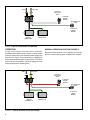
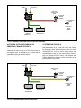
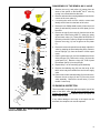
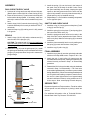
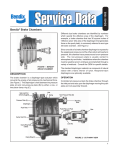
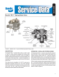
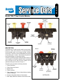
SD-03-3415
Bendix® MV-3® Dash Control Module
Dual Circuit
SUPPLY
Check VALVE
MOUNTING
HOLES
(4)
MOUNTING
PLATE
AUXILIARY
PORT
(Optional)
tractor
delivery
secondary
supply
Trailer
delivery
supply #1
(Primary)
EXHAUST
FIGURE 1 - Bendix® MV-3® Dash Control Module
DESCRIPTION
The Bendix ® MV-3 ® dash control module is a two-button,
push-pull control valve housed in a single body that
accommodates dual circuit supply through a double
check valve. The MV-3 valve can duplicate the functions
of any existing two- or three- valve push-pull system and
has the advantages of reduced plumbing.
exhaust
supply #1
(Primary)
The MV-3 valve body, plungers and spools are made out of
a non-metallic, non-corrosive material. All air connections
are at the back of the valve with the exception of the
optional auxiliary port as shown in Figure 1.
The MV-3 valve provides the following functions:
1 - Tractor Protection
2 - Trailer Service Air Control
3 - System Park
4 - Trailer Park Only
5 -Trailer Charge with Tractor Spring Brakes Applied
(Tractor Park Only)
6 - Primary & Secondary Reservoir Connections
auxiliary
delivery
port
TRAILER
DELIVERY
supply #2
(Secondary)
TRACTOR
DELIVERY
Bottom View
7 - Dual Supply Reservoir Isolation via the Check Valve
1
red
yellow
tractor
protection
valve
(; +
To Trailer
spring
brakes
6 83
Quick Release
valve
To tractor
spring
brakes
tractor
service
reservoir #2
tractor service
reservoir #1
FIGURE 2 - INITIAL CHARGING OR SYSTEM PARK
(; +
6 83
OPERATION
Normal Operating Position (Figure 4)
During initial charge, with the system completely
discharged, both buttons are out (Figure 2). When system
pressure reaches 65 psi, the red button (trailer supply) may
be pushed in (Figure 3) and should stay in, charging the
trailer system and releasing the trailer brakes. The yellow
button may now be pushed in, which will supply air to the
tractor spring brakes, releasing them.
(; +
6 83
red
With both buttons pushed in, air is supplied to the trailer
and to the tractor spring brakes; all brakes are released.
yellow
(; +
(; +
tractor
protection
valve
6 83
To Trailer
spring
brakes
6 83
Quick Release
valve
To tractor
spring
brakes
tractor
service
reservoir #2
(; +
tractor service
reservoir #1
6 83
FIGURE 3 - TRAILER CHARGED & TRACTOR PARKED
(; +
2
6 83
yellow
red
tractor
protection
valve
(; +
To Trailer
spring
brakes
6 83
Quick Release
valve
(; +
6 83
To tractor
spring
brakes
tractor
service
reservoir #2
tractor service
reservoir #1
FIGURE 4 - Normal Operating Position Tractor & Trailer
(; +
6 83
System Park (Figure 2)
Actuation of Trailer Parking or
Emergency Brakes (Figure 5)
To actuate only the trailer brakes, pull out the red button,
exhausting the trailer supply line. The trailer brakes are
now applied either by emergency air or spring brakes,
depending on the type of trailer system.
(; +
6 83
red
With both buttons in for normal run modes, the parking
brakes on both the tractor and trailer may be actuated
by pulling the yellow (parking brake) button out—which
exhausts the air from the tractor spring brakes and
simultaneously causes the red (trailer supply) button to
pop out, applying the trailer brakes. This complies with
Federal Regulations that one control must apply all the
parking brakes on the vehicle.
yellow
tractor
protection
valve
(; +
To Trailer
spring
brakes
6 83
Quick Release
valve
To tractor
spring
brakes
tractor
service
reservoir #2
tractor service
reservoir #1
figurE 5 - Trailer Parked Tractor Released
3
Trailer Charge (Figure 3)
If both buttons are out when parking the combination
vehicle and it is desired to recharge the trailer (leaving
the tractor spring brakes applied), the red button may be
pushed in, repressurizing the trailer supply line. This mode
might also be used to park a combination vehicle—with
air actuated emergency brakes on the trailer—to provide
demonstrated parking capability with tractor spring brakes
only.
Automatic Application
With both buttons in (the normal run configuration), if the
supply pressure to the push-pull valves is reduced to
approximately 20 to 45 psi, the red button (trailer supply
valve) must pop out, applying the emergency or parking
brakes on the trailer. If the red button is held in manually
and the pressure decreases to approximately 20 psi, a trip
piston within the Bendix® MV-3® valve will move upward—
exhausting the trailer supply—effecting the required
non-override feature.
Operational TEST
1. With supply pressure at 120 psi, push the red button
in. The button must stay in.
2. Slowly reduce pressure in both service reservoirs. The
red button must pop when supply pressure drops to 20
to 45 psi.
3. Hold the red button in and continue to reduce pressure
in all service reservoirs. Air must start to escape from
the exhaust port when the trailer supply line pressure
reaches 20 psi minimum.
4. Release the red button and rebuild the supply pressure
to at least 120 psi. Push in the yellow button; the yellow
button must remain in.
5. Charge the system to 120 psi and push both buttons in.
Pull the red button out. The yellow button must remain
in.
6. Push the red button in and pull the yellow button out.
The red button must pop out almost instantaneously.
7. Build both service reservoirs to 120 psi. Decrease
the pressure at the secondary reservoir. The primary
reservoir pressure should not drop below 100 psi.
Repeat the test for decreasing primary reservoir
pressure. The secondary reservoir pressure should
not drop below 100 psi.
8. If the MV-3 valve fails to operate as described, replace
or repair it using genuine Bendix® parts.
9. Close all reservoir drain cocks and deliberately caused
leakage points before placing the vehicle back into
service.
CAUTION: Note the orientation of the buttons in relation to
the valve to be sure they will be replaced properly.
Note: The yellow button must not pop out before the
red button.
gENERAl SAFETy guIDElINES
WARNINg! PlEASE READ AND FOllOW ThESE INSTRuCTIONS
TO AVOID PERSONAl INJuRy OR DEATh:
When working on or around a vehicle, the following guidelines should be observed AT All TIMES:
▲ Park the vehicle on a level surface, apply the
parking brakes and always block the wheels.
Always wear personal protection equipment.
▲ Stop the engine and remove the ignition key
when working under or around the vehicle.
When working in the engine compartment,
the engine should be shut off and the ignition
key should be removed. Where circumstances
require that the engine be in operation, ExTREME
CAuTION should be used to prevent personal
injury resulting from contact with moving,
rotating, leaking, heated or electrically-charged
components.
▲ Do not attempt to install, remove, disassemble
or assemble a component until you have read,
and thoroughly understand, the recommended
procedures. use only the proper tools and
observe all precautions pertaining to use of those
tools.
▲ If the work is being performed on the vehicle’s
air brake system, or any auxiliary pressurized air
systems, make certain to drain the air pressure
from all reservoirs before beginning ANy work
on the vehicle. If the vehicle is equipped with a
Bendix® AD-IS® air dryer system, a Bendix® DRM™
dryer reservoir module, or a Bendix® AD-9si™ air
dryer, be sure to drain the purge reservoir.
▲ F o l l o w i n g t h e v e h i c l e m a n u f a c t u r e r ’s
recommended procedures, deactivate the
electrical system in a manner that safely removes
all electrical power from the vehicle.
▲ Never exceed manufacturer’s recommended
pressures.
▲ Never connect or disconnect a hose or line
containing pressure; it may whip. Never remove
a component or plug unless you are certain all
system pressure has been depleted.
▲ use only genuine Bendix ® brand replacement
parts, components and kits. Replacement
hardware, tubing, hose, fittings, etc. must be of
equivalent size, type and strength as original
equipment and be designed specifically for such
applications and systems.
▲ Components with stripped threads or damaged
parts should be replaced rather than repaired.
Do not attempt repairs requiring machining or
welding unless specifically stated and approved
by the vehicle and component manufacturer.
▲ Prior to returning the vehicle to service, make
certain all components and systems are restored
to their proper operating condition.
▲ For vehicles with Automatic Traction Control
(ATC), the ATC function must be disabled (ATC
indicator lamp should be ON) prior to performing
any vehicle maintenance where one or more
wheels on a drive axle are lifted off the ground
and moving.
▲ The power MuST be temporarily disconnected
from the radar sensor whenever any tests uSINg
A DyNAMOMETER are conducted on a Bendix®
Wingman® Advanced™-equipped vehicle.
▲ you should consult the vehicle manufacturer's operating and service manuals, and any related literature,
in conjunction with the guidelines above.
4
DISASSEMBLY OF THE Bendix® MV-3® VALVE
1
1. Remove the red (1) and yellow (2) buttons from the
stems of the spools on the Bendix® MV-3® valve by
turning in a counterclockwise direction.
2
4
2. Remove and save the mounting hardware from the four
corners of the cover plate (3).
3. If removing the valve from the vehicle, remove and
identify the air lines from the back of the valve.
4. Remove the six Phillips head screws (4) from the cover
plate (3) and carefully remove the cover plate (3) from
the valve.
16
3
16
14
18
14
19
5
15
18
6
7
19
15
11
8
21
12
21
20
10
6. Remove the two main spools from the body of the MV-3
valve by grasping the stem and pulling firmly. Remove
the two springs (12) from the bottom of each spool
cavity.
7. Pull the guide spool (14) over the threaded end of one
of the plungers (15). Remove the o-ring (16) from the
guide spool (14). Remove o-rings (18, 19 & 20) and
the exhaust seal (21) from the plunger.
8. Repeat Step 7 on the remaining spool assembly.
20
9
5. Remove the cap (5) and o-ring (6) from the bore of the
tripper valve. Remove the piston (7), spring (8), spring
(9) and check valve (10). These parts will all fall out of
the cavity of the MV-3 valve by tilting the body forward.
Remove the o-ring (11) from its groove on the piston
(7).
12
9. Remove the retaining ring (22) from the cavity of the
MV-3 valve body that contains the dual circuit supply
valve.
10.Pull the check valve seat assembly (23) from the valve.
Remove the two o-rings (24 and 13) from the check
valve assembly. Remove the check valve (17) from
the MV-3 valve body.
CLEANING & INSPECTION
17
13
24
valve body
23
The non-metallic components which comprise most of the
parts of the MV-3 valve should not be immersed in any
solvent type cleaner. Old lubricant should be wiped out
with a clean dry cloth.
If any visible damage to the body or the spools can be
detected, the complete unit must be replaced.
22
FIGURE 6 - Bendix® MV-3® dash control module
Parts Exploded view
5
ASSEMBLY
Dual Circuit Supply Valve
1.Lubricate all o-rings and bores with silicone lubricant.
(Bendix piece number 291126 or Dow Corning 55-M.)
2. Place the check valve (17) into its seat in the body with
its flat surface facing upward. If necessary, reach into
the body to make sure the valve is seated evenly in the
bore.
3. Install the spring (12) over the boss in the bottom of
the spool cavity in the body of the MV-3 valve. Place
the spool assembly into the body, keeping the spool
square to the body press and turn the stem until the
spool is fully seated in its cavity. Note the assembly is
keyed and may only be installed one way.
4. Repeat Steps 1, 2, and 3 with the remaining components
for the opposite spool.
3. Install o-rings (24 & 13) onto the check valve (23). Then
install the assembly into its cavity in the Bendix® MV-3®
valve body.
Shuttle and Check Valve
4. Install the snap ring (22) making sure it is fully seated
in its groove.
2. Install the spring (8) on the piston (7) and spring (9) on
the boss of the check valve (10).
Spools
3. Install the spring and check valve into its cavity in the
body of the MV-3 valve (tapered end of check valve to
enter cavity first). Make sure the spring (9) is centered
in the bore.
1. Install o-rings (18,19 & 20) and the exhaust seal (21)
onto the stem of the plungers (15).
CAUTION: The exhaust seal (21) must be installed so
that its beveled surface mates with the beveled surface
of the plunger (Figure 7).
2. Install the o-ring (16) onto the guide spool (14). Install
the guide spool assembly over the threaded end of the
plunger (15) and press down firmly until it contacts the
plunger flange.
15
PLUNGER
18
O-RING
19
O-RING
I.D.
BEVEL
MATING
EXHAUST
SEAl
BEVEL
20
O-RING
21
EXHAUST SEAL
FIGURE 7 - PLUNGER AND EXHAUST SEAL
6
1. Install the o-ring (11) into its groove on the piston (7) and
o-ring (6) onto the cap (5).
4. Install the piston assembly into the cavity making sure
the spring (9) mates with the bore of the piston.
5. Install the cap (5) with o-ring (6).
FINAL ASSEMBLY
1. Install the cover plate (3) onto the valve body and retain
with the six Phillips head screws. Torque to 30 in. Ibs.
2. Attach the red (1) and yellow (2) buttons onto the
threaded stems of the spools, making sure that they are
oriented correctly as noted in Step 1 of Disassembly
procedure.
3. Reattach the MV-3 valve to the dash using the hardware
removed in Step 2 of Disassembly. If air lines were
removed during disassembly, reconnect to ports marked
during disassembly. When reconnecting threaded ports
use a liquid thread sealing compound, attach the air
line until it is hand tight and then turn approximately
one and a half turns further (or using a maximum of 10
ft.-lbs. torque - Note: overtorquing will crack the port).
Service Test
Repeat the Operational Test procedures. Test drive vehicle
at slow speed in a safe area prior to placing it back into
service.
For additional information refer to Technical Bulletin Bendix Dash Valve Trip Pressure TCH-003-051.
7
BW1613 © 2012 Bendix Commercial Vehicle Systems LLC, a member of the Knorr-Bremse Group • 3/2012 • All Rights Reserved
8