1
SD-11-1326
®
Bendix® AH-1B™ Air Hydraulic Intensifier
ELECTRICAL FLUID
LEVEL INDICATOR
CONNECTION
BRAKE FLUID
RESERVOIR
RESERVOIR
CAP
AIR
INLET
PORT
ACTUATOR
BRAKE FLUID
DELIVERY PORT
MASTER
CYLINDER
MOUNTING
BRACKET
NON-PRESS
PLATE
CLAMP RING
AIR INLET
ELECTRICAL
CONNECTOR
RETURN
SPRING
INDICATOR
SWITCH
FILLER CAP
ASSY.
BOOT
RESERVOIR
PRESSURE
PLATE
FLOAT
DIAPHRAGM
PUSH ROD
SEAL
O-RING
DRAIN HOLE
PISTON
MOUNTING
BRACKET
COMPENSATING
VALVE
HYD.
DELIVERY
PORT
RETURN
SPRING
PISTON
ACTUATOR
LIP
FIGURE 1
DESCRIPTION
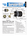
The AH-1B™ air hydraulic intensifier is a hydraulic brake,
power booster which utilizes compressed air for its power
assist. Its function is to convert air pressure to hydraulic
pressure for use in the brake system.
The AH-1B™ intensifier consists of three major component
groups; a specially designed type 30 air actuator is bolted
to a single piston master cylinder which incorporates an
integral brake fluid reservoir. A bracket installed between the
actuator and master cylinder provides a means for mounting.
A float actuated, low fluid level, on/off electrical switch is
incorporated in the reservoir filler cap assembly. A two
“prong” connector is provided to permit the installation of a
vehicle electrical cable assembly. Switch actuation occurs
when the reservoir fluid level drops below the “minimum”
level marking on the reservoir.
1
SPRING BRAKE
ACTUATOR
HYDRAULIC
DISC BRAKE
PUSH-PULL VALVE
AH-1B™ AIR OVER
HYDRAULIC
INTENSIFIER
BRAKE
VALVE
RELAY
VALVE
AIR DRYER
RESERVOIR
COMPRESSOR
FIGURE 2 - TYPICAL AH-1B™ AIR HYDRAULIC INTENSIFIER SYSTEM
AIR APPLIED
POSITION
DIAPHRAGM
APPLIED
POSITION
COMPENSATING
TILT VALVE SEALED
HYDRAULIC FLUID
BEING DELIVERED
PISTON APPLIED
POSITION
RETURN
SPRING
COMPRESSED
FIGURE 3 - CUTAWAY VIEW OF APPLIED POSITION
2
AIR INLET
NON-APPLIED POSITION
DIAPHRAGM
NON-APPLIED POSITION
COMPENSATING TILT
VALVE UNSEALED
POSITION
HYDRAULIC
FLUID PORT
PISTON
NON-APPLIED
POSITION
RETURN SPRING
NON-APPLIED POSITION
FIGURE 4 - CUTAWAY VIEW OF RELEASED POSITION
OPERATION
Brakes Applied
During a brake application, modulated air pressure from the
foot operated air brake valve enters the actuator inlet port.
Air pressure acting upon the area of the actuator diaphragm
causes the diaphragm and push rod assembly to move
toward the master cylinder. The actuator push rod forces
the master cylinder piston to move within its bore. Initial
forward travel of the piston moves the actuating lip of the
piston away from the stem of the compensating (tilt) valve
allowing it to close due to spring force. (Refer to Figure 2 &
3.) Closure of the compensating valve shuts off the fluid
passage between the cylinder bore and fluid reservoir which
allows hydraulic pressure to build and the brakes to apply.
The amount of hydraulic pressure generated is dependent
upon the air pressure applied to the air actuator.
Brakes Released
When air pressure is exhausted from the actuator the push
rod returns to the released position due to spring force.
With the push rod load removed, fluid pressure combined
with return spring force causes the piston to return to the
brakes released position. The actuator lip of the piston
contacts the stem of the compensating valve and unseats
the valve as the piston returns. When the compensating
valve opens, the passage between the fluid reservoir and
master cylinder bore is also open. Any excess fluid
remaining at the end of the stroke due to “pumping” and/or
volume change due to temperature fluctuation is transmitted
back to the fluid reservoir as the compensating valve opens.
The push rod is used as the piston stop in the fully released
position. (Refer to Figure 4).
Fluid Level Indicator
The reservoir fluid level is reduced as the brake linings wear
due to an increase of fluid volume required in the hydraulic
brake system. The float contained in the reservoir filter cap
assembly is suspended in the reservoir fluid and responds
to changes in the fluid level. As long as the reservoir fluid
level is adequate, a metal contact plate on top of the float
stem is held away from two electrical contacts. When the
reservoir fluid level drops below the “MINIMUM” fluid level
mark on the reservoir, the contact plate on the float stem
will move and complete the electrical circuit through the
switch.
3
TECHNICAL SPECIFICATIONS
™
AH-1B Air Hydraulic Intensifier Assembly
Power ratio - 20.2 to 1
Weight - approximately 2-1/2 pounds
Air Actuator
Effective area of diaphragm at 2-1/8 inches of push rod stroke
- approximately 28 sq.in.
Volume at 2-1/8 inches of push rod stroke - approximately
75 cubic inches.
Master Cylinder
Bore diameter - 1.38 inches
Maximum piston stroke - 2-1/8 inches
Maximum fluid displacement - 3.17 cubic inches
Fluid Reservoir
Volume - 33.5 cubic inch to “MAXIMUM” level mark with
cap removed.
PREVENTIVE MAINTENANCE
Every month, after 8,000 miles, or 300 operating hours;
1. Remove accumulated dirt and grime from the area
around the reservoir cover. With the ignition switch in
the on position, remove the cover and hold in an upright
position and allow brake fluid in the tube of the cap to
drain back into the reservoir. Check to see if the low
fluid indicator bulb is operating (in cab of vehicle).
2. If the fluid level is low, fill to proper level indicated on the
side of the reservoir. CAUTION: Fill the reservoir with
type and grade of fluid recommended by the vehicle
manufacturer.
3. Check tightness of the mounting nuts, air and hydraulic
fittings.
4. Make a visual inspection of air and hydraulic lines for
kinking, bending or fraying. Replace as necessary.
Every 12 months; 100,000 miles; or 3,600 operating hours;
1. Perform the operating and leakage tests. Replace or
repair components or assemblies as indicated using
only genuine Bendix parts.
OPERATING AND LEAKAGE TESTS
1. With vehicle air system pressure built to governor cut-out,
make and hold a full brake application. Hold for at least
5 minutes. Using a soap solution, check for air leaks at
fittings and air lines. Tighten and/or replace as necessary.
Apply a soap solution around the actuator clamp ring.
No leakage is permitted. Tighten or replace as necessary.
Apply a soap solution to the actuator non-pressure plate
drain holes. Replace the actuator diaphragm if leakage
is detected.
4
2. While holding the brake valve in the fully applied position,
check for hydraulic fluid leaks at all fitting connections
and at the hydraulic cylinders in the foundation brake.
Check for fluid leakage at the drain holes of the actuator
non-pressure plate. Repair or replace components as
necessary.
3. With the reservoir filter cap removed apply and fully
release the brakes several times while observing the fluid
in the reservoir. CAUTION: WEAR SAFETY GLASSES
AS FLUID MAY EXIT THE RESERVOIR.
A slight fluid turbulence should be noted at the beginning
of the application and should immediately cease. If
prolonged turbulence is noted, the master cylinder must
be repaired or replaced.
WARNING! PLEASE READ AND FOLLOW
THESE INSTRUCTIONS TO AVOID
PERSONAL INJURY OR DEATH:
When working on or around brake systems and
components, the following precautions should be
observed at all times:
1. Park the vehicle on a level surface, apply the
parking brakes, and always block the wheels.
When working around or under the vehicle, stop
the engine and remove the key from the ignition.
Always keep hands away from chambers as they
may apply as system pressure drops. Always wear
safety glasses.
2. When working in the engine compartment, the
engine should be shut off and the ignition key
should be removed. Where circumstances require
that the engine be in operation, extreme caution
should be used to prevent personal injury resulting
from contact with moving, rotating, leaking, heated
or electrically charged components.
3. Do not attempt to install, remove, disassemble or
assemble a component until you have read and
thoroughly understand the recommended
procedures. Use only the proper tools and observe
all precautions pertaining to the use of those tools.
4. Following
the
vehicle
manufacturer’s
recommended procedures, deactivate the electrical
system in a manner that safely removes all
electrical power from the vehicle.
5. If the vehicle is equipped with an air over hydraulic
brake system or any auxiliary pressurized air
system, make certain to drain the air pressure from
all reservoirs before beginning ANY work on the
vehicle. If the vehicle is equipped with an AD-IS™
air dryer system or a dryer reservoir module, be
sure to drain the purge reservoir.
6. Never connect or disconnect a hose or line
containing pressure; it may whip. Never remove a
component or pipe plug unless you are certain all
system pressure has been depleted.
7. Never exceed manufacturer’s recommended
pressure.
DIAPHRAGM
NUT (2)
NON-PRESS
PLATE
BUSHING
ASSEMBLY
RETURN
SPRING
SPRING
SEAT
PRESSURE
PLATE
BOOT
1-1/4” RES.
RETAINING
NUT
CLAMP RING
RESERVOIR
RESERVOIR CAP
ASSEMBLY
SEAL
MASTER
CYLINDER BODY
LOCKWASHER
(2)
ACTUATOR
NUT (2)
COMPENSATING
(TILT) VALVE
ASSEMBLY
RESERVOIR
MTG. PAD
WASHER (2)
O-RING
SPRING
O-RING
PISTON ASSY.
(W/ SEAL)
GASKET
MOUNTING
BRACKET
PHILLIPS
SCREW (2)
FIGURE 5 - EXPLODED VIEW
8. Never attempt to disassemble a component until
you have read and understand all recommended
procedures. Some components contain powerful
springs and injury can result if not properly
disassembled. Use only proper tools and observe
all precautions pertaining to use of those tools.
9. Use only genuine Bendix ® replacement parts,
components and kits.
A. Use only components, devices and mounting
and attaching hardware specifically designed
for use in hydraulic brake systems.
B. All replacement hardware, tubing, hose,
fittings, etc. must be of equivalent size, type
and strength as the original equipment.
10. Components with stripped threads or damaged
parts should be replaced rather than repaired. Do
not attempt repairs requiring machining or welding
unless specifically stated and approved by the
vehicle and component manufacturer.
11. Prior to returning the vehicle to service, make
certain all components and systems are restored to
their proper operating condition.
FIGURE 6
5
REMOVAL FROM VEHICLE
1. Disconnect the hydraulic line from the delivery port of
the master cylinder and plug the line. Allow the hydraulic
fluid from the master cylinder to drain into a suitable
container. Remove reservoir cover to facilitate drainage.
2. Disconnect the air line from the air actuator and cover
the end of the air line.
3. Remove the electrical connection from the low level
indicator on the reservoir cover.
4. Remove the hardware that secures the mounting bracket
of the AH-1B™ intensifier to the vehicle and remove the
complete unit.
INSTALLING ON VEHICLE
1. Install the hardware which secures the AH-1B™ intensifier
mounting bracket to the vehicle. Torque all hardware per
the vehicle manufacturer’s recommendations.
2. Reconnect the air line to the actuator. Use a small amount
of thread sealant.
3. Reconnect the hydraulic line to the master cylinder.
4. Connect the electrical terminal from the low fluid indicator
onto the terminal on the cap of the reservoir.
5. Fill the master cylinder fluid reservoir using the type and
grade fluid specified by the vehicle manufacturer.
6. Bleed the hydraulic brakes following the vehicle
manufacturer’s recommended procedure.
7. Refill the master cylinder fluid reservoir to replace fluid
lost during the bleeding procedure.
DISASSEMBLY
General
The following procedure is presented for reference only.
Disassembly of the AH-1B™ intensifier should not be
attempted without having the appropriate maintenance kits
or replacement parts on hand as some parts may be
damaged during disassembly.
FIGURE 7
6
FIGURE 8
1. Drain the hydraulic fluid from the reservoir.
2. Remove the two Phillips screws and lockwashers from
the bottom of the reservoir located at the reservoir
mounting pad on the master cylinder next to the flange.
3. Remove the reservoir cap and retain. DO NOT
DISASSEMBLE CAP. Using a 1-1/4" socket remove the
retaining nut on the inside of the reservoir. Reservoir is
now free of the master cylinder. Remove the seal on the
bottom of the reservoir and discard. (Refer to Figure 6.)
4. Remove the compensating valve assembly from the
master cylinder by placing a crescent wrench across
the flats and turning counterclockwise. If only changing
the reservoir, do not remove the compensating valve
assembly as it cannot be replaced unless the master
cylinder is disassembled. The compensating valve must
be replaced as an assembly (Figure 7).
FIGURE 9
5. Note and mark the orientation of the actuator and master
cylinder to the mounting bracket. Remove the two nuts
and washers from the mounting studs of the actuator
(use a 15/16" socket wrench). Separate the master
cylinder and actuator from the mounting bracket and
retain the actuator for later disassembly. CAUTION:
Piston under spring load and retained by the push rod
only when compensating tilt valve assembly has been
removed. (Refer to Figure 8.)
6. Remove the o-ring from the flange of the master cylinder
and the gasket between the bracket and actuator.
7. Remove the piston assembly and spring from the body
of the master cylinder. (Refer to Figure 9.)
Actuator Disassembly
8. Mark the relationship of the clamp ring, pressure and
non-pressure plates. Remove the two nuts and bolts from
the clamp ring of the actuator (use a 1/2" socket wrench).
Grasp the ears of the clamping ring and spread slightly
until ring will come off and pressure plate and
non-pressure plates separate. CAUTION: Parts are
spring loaded. Use a press or clamp to retain the push
rod and return spring during disassembly.
9. Remove the spring seat, spring, and boot from the push
rod and separate the diaphragm from the push rod.
(NOTE: Do not separate the diaphragm from the push
rod.) If the diaphragm is to be replaced, a new push rod
and diaphragm assembly will be required.
CLEANING & INSPECTION
1. Wash all master cylinder parts retained during
disassembly in clean DOT 3 or 4 brake fluid. CAUTION:
DO NOT use any solvent other than clean brake fluid
for cleaning or flushing master cylinder parts. The use
of unapproved solvents with a trace of mineral oil will
damage rubber parts.
2. Remove all sediment or foreign material from the bottom
of the fluid reservoir. If the reservoir is equipped with
filters, make certain they are thoroughly cleaned. If the
filters are thoroughly plugged and/or cannot be cleaned,
the entire brake system should be flushed. If the filter
cannot be cleaned, it may be removed after the system
is flushed.
3. Inspect the condition of the piston. Measure the major
diameter (around the top edge of the o-ring groove and
piston actuator lip) of each piston in several places around
its circumference. The difference between the largest
and smallest measurement on each of the diameters
measured should not exceed .005 inches (.13mm). If
the diameter of the piston varies more than the maximum,
the master cylinder should be replaced or repaired using
a maintenance kit.
FIGURE 10
4. Examine the master cylinder bore after cleaning. If pitting,
scratching or visible wear patterns are noted, the master
cylinder should be replaced. Dirt, gum and stained areas
not removed during cleaning can be polished with crocus
cloth. DO NOT USE EMERY CLOTH OR SAND PAPER.
Master cylinder bores may be honed provided that the
diameter is not increased substantially. Honing to remove
scratches and pitting will most likely increase the bore
diameter beyond the sealing ability of piston seals. To
make certain the bore diameter has not been excessively
increased, measure the piston clearance in the master
cylinder bore. Using a feeler gauge make certain the
clearance does not exceed .010 inches (.25 mm). Make
certain that no burrs or sharp edges remain in the cylinder
bore. Thoroughly clean and rinse the master cylinder in
brake fluid after polishing or honing.
5. Inspect the actuation push rod return spring for corrosion
and pitting and replace if necessary.
6. Inspect the actuator diaphragm for wear and abrading.
(It is recommended that the diaphragm be replaced
whenever a complete disassembly of the AH-1B ™
intensifier takes place.)
7. The push rod boot should be replaced each time a
complete disassembly is undertaken.
ASSEMBLY
Actuator Assembly
1. Install the boot onto the push rod assembly. The small
I.D. of the boot must be forced over the larger O.D. on
the shaft of the push rod. Place the spring over the
push rod and boot and place the spring seat onto the
spring. Force large flange end of the boot through the
center hole of the spring seat.
7
2. Place the push rod and diaphragm assembly into the
pressure plate and place non-pressure plate onto the
push rod. Check to assure that the spring is in proper
position (each end contained and centered in the spring
guides).
3. Orient the pressure and non-pressure plates as marked
and compress the spring by pushing down on the
non-pressure plate. Retain with a clamp or light pressure
from a press. Be sure the ferrule on the pressure plate
is properly oriented and the edges of the non-pressure
plate, diaphragm, and pressure plate are equally
distributed around the entire circumference.
4. Install clamping ring and retain with the two bolts and
nuts. Torque to 130-150 inch pounds. IMPORTANT: Be
sure the beads of the pressure plate and the non-pressure
plate are contained by the clamping ring a full 360°. Tap
around the circumference of the clamp ring to assure it
is seated evenly all around.
FIGURE 11
5. Install a new gasket on the mounting studs of the
nonpressure plate of the assembled actuator and put
the assembly aside.
12. Install the new gasket(6) over the mounting studs of the
brake chamber. Make sure the gasket is flat against the
top of the brake chamber.
Master Cylinder Assembly
13. Place the brake chamber onto the mounting bracket with
the push rod extending through the center hole and the
mounting bolts extending through the outer holes.
6. Install new o-rings on the master cylinder mounting flange
and the master cylinder piston.
7. Carefully insert the spring and piston into the master
cylinder body. Making certain not to damage the seal
and o-ring. The lip seal and o-ring must enter the body
last. Depress and hold the piston by inserting a dull
object into the recess in the end of the piston. Piston
actuator lip should be completely past the compensating
TRT valve assembly port to allow for proper installation
of the compensating valve assembly. Install the
compensating valve assembly into the threaded port of
the top of the master cylinder. Be sure compensating
valve is installed between the two larger diameters on
the piston. Torque to 30-40 foot pounds. NOTE: The
compensating valve assembly should retain the piston
assembly in the master cylinder if installed correctly.
(See Figure 10.)
14. Install the master cylinder/reservoir assembly onto the
brake chamber mounting studs and retain with nuts(4)
and washers(5). Torque to 100-115 foot pounds. NOTE:
The end of the push rod must enter the recess of the
master cylinder piston.
8. Install a new seal on the bottom of the reservoir and
place both on the master cylinder. Be sure reservoir is
oriented so that holes for the Phillips screws line up
with the holes on the master cylinder. Install the two
Phillips screws and lockwashers and tighten snugly.
2. Fill reservoir with brake fluid. Refer to vehicle
manufacturer’s manual for fluid requirements.
Bench Bleeding
Before installing the AH-1B™ intensifier assembly on the
vehicle the master cylinder should be bench bled. Follow
the vehicle manufacturer’s recommendations in lieu of the
following.
1. Plug outlet port and secure cylinder in a vise with front
end tilted slightly downward. NOTE: Bleeder tubes or
Bendix bleeding kit #74013 may also be used following
the kit instructions enclosed. (Refer to Figure 11.)
3. Apply and release air pressure to the actuator several
times.
10. Install the reservoir filler cap assembly on the reservoir.
4. Re-position the master cylinder in the vise with the front
end tilted slightly up. Again, apply and release air
pressure several times. NOTE: When using this method
of bench bleeding, the master cylinder will not be capable
of being stroked once all the air is removed.
11. Clamp the mounting bracket securely in a vise, making
sure it is oriented so that the unit may be assembled,
and lining up the marks made prior to disassembly.
5. Install the AH-1B™ intensifier on the vehicle and perform
the “Operating and Leakage Tests” prior to placing the
vehicle in service.
9. Install the reservoir retaining nut onto the compensating
valve through the reservoir cover opening. Use a 1-1/4"
socket and torque to 13-16 foot pounds.
8
BW1599 © 2004 Bendix Commercial Vehicle Systems LLC All rights reserved. 4/2004 Printed in U.S.A.