1
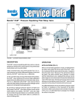
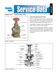
SD-07-2601
®
Bendix® C-5™ Cut-Out Cock
OPERATING HANDLE
LOCK NUT
STEM
STEM
WASHER
O-RING
CAP NUT
REDUCER
BUSHING
O-RING
VALVE SEATS
VALVE
BODY
CLAMPING
STUD
FIGURE 1
DESCRIPTION
LEAKAGE CHECK
The C-5™ cut-out cock is a manually operated on-off valve.
Cut-out cocks are used in an air brake system where a
manual shut off air lines is desirable such as in trailer and
trailer dolly systems.
With the valve in the closed position and air pressure present
on either side, a soap solution is applied to the side open to
atmosphere. A leakage of not more than a 1" bubble in 5
seconds is permitted.
OPERATION
Note that in Figure 1 the C-5™ cut-out cock uses a metal
ball valve between two valve seats. Rotating the ball valve
90° will either open or close the air passage through the
cut-out cock.
PREVENTIVE MAINTENANCE
Every six months, 1800 operating hours, or 50,000 miles
the cut-out cock should be checked for leakage around the
ball valve and past the stem o-ring. Once each year, 3600
hours, or 100,000 miles the C-5™ cut-out cock should be
disassembled, cleaned, and inspected for signs of wear or
deterioration.
NOTE: Leakage should be checked in each direction since
it is possible for the valve to seal in one direction
but not the other.
If the cut-out cock leaks excessively or if wear or deterioration
is noted during routine maintenance, it is recommended that
it be replaced with a new unit or repaired with genuine Bendix
parts.
REMOVING AND INSTALLING
REMOVING
Block and hold vehicle by means other than air brakes.
Completely drain all reservoirs. Disconnect air lines from
both sides of the cut-out cock.
1
INSTALLING
Prior to installing, check, and if necessary, clean or replace
lines leading to the cut-out cock.
Install the valve taking care the operating handle is in a
convenient position for use.
DISASSEMBLY
Unscrew cap nut from body and remove cap nut o-ring.
NOTE: Early models of the C-5™ cut-out cock had a cap
nut at both ends of the body. Parts from the earlier
model C-5™ cut-out cock are not interchangeable
with the new model and are not available. When
service is required on the older model it should be
replaced with the current style.
Rotate the operating handle of the cut-out cock until the
passage through the valve is closed. Note the position of
the handle for reassembly.
Lightly tap the open end of the valve body on the work
surface. The ball valve and both seats will drop out.
Remove the lock nut located in the center of the operating
handle and remove the handle from the stem.
Remove handle stem by pushing into valve body and shaking
out.
Remove stem washer and o-ring from stem.
CLEANING AND INSPECTION
Wash all metal parts in mineral spirits.
Ball valve seats and o-rings should be wiped clean.
Inspect seats and o-rings for nicks, wear or deterioration.
Inspect valve body, cap nut, handle and stem for cracks and
wear. Any part considered unserviceable will necessitate
that the entire valve be rebuilt or replaced.
ASSEMBLY
All o-rings should be lightly lubricated with Bendix silicone
lubricate BW650M piece no. 291126.
Position stem washer and o-ring on stem.
Push stem through body (threaded end first) from the inside
out.
Position operating handle on stem and replace and tighten
stem lock nut. Torque to 30-70 inch pounds.
Position one of the two valve seats in the body with the
contoured side up.
Place operating handle in position noted during disassembly.
(Drive tang on end of stem should be parallel with center line
of body.)
Place ball valve in body with slot coinciding with stem.
Place remaining valve seat in body with contoured side down
and against the ball valve.
2
Place o-ring on cap nut and install cap nut in body and
tighten (Torque to 150-400 inch pounds).
TESTING
Perform leakage test on reassembled or rebuilt valve.
WARNING! PLEASE READ AND FOLLOW
THESE INSTRUCTIONS TO AVOID
PERSONAL INJURY OR DEATH:
When working on or around a vehicle, the following
general precautions should be observed at all times.
1. Park the vehicle on a level surface, apply the
parking brakes, and always block the wheels.
Always wear safety glasses.
2. Stop the engine and remove ignition key when
working under or around the vehicle. When
working in the engine compartment, the engine
should be shut off and the ignition key should be
removed. Where circumstances require that the
engine be in operation, EXTREME CAUTION should
be used to prevent personal injury resulting from
contact with moving, rotating, leaking, heated or
electrically charged components.
3. Do not attempt to install, remove, disassemble or
assemble a component until you have read and
thoroughly understand the recommended
procedures. Use only the proper tools and observe
all precautions pertaining to use of those tools.
4. If the work is being performed on the vehicle’s air
brake system, or any auxiliary pressurized air
systems, make certain to drain the air pressure from
all reservoirs before beginning ANY work on the
vehicle. If the vehicle is equipped with an AD-IS™
air dryer system or a dryer reservoir module, be
sure to drain the purge reservoir.
5. Following
the
vehicle
manufacturer’s
recommended procedures, deactivate the electrical
system in a manner that safely removes all
electrical power from the vehicle.
6. Never exceed manufacturer’s recommended
pressures.
7. Never connect or disconnect a hose or line
containing pressure; it may whip. Never remove a
component or plug unless you are certain all
system pressure has been depleted.
8. Use only genuine Bendix ® replacement parts,
components and kits. Replacement hardware,
tubing, hose, fittings, etc. must be of equivalent
size, type and strength as original equipment and
be designed specifically for such applications and
systems.
9. Components with stripped threads or damaged
parts should be replaced rather than repaired. Do
not attempt repairs requiring machining or welding
unless specifically stated and approved by the
vehicle and component manufacturer.
10. Prior to returning the vehicle to service, make
certain all components and systems are restored
to their proper operating condition.
BW1596 © 2004 Bendix Commercial Vehicle Systems LLC All rights reserved. 4/2004 Printed in U.S.A.