1
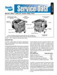
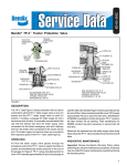
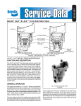
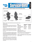
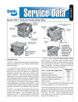
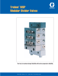
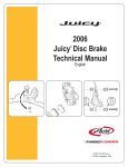
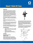
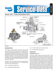
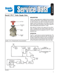
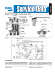
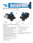
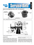
SD-03-3617
Bendix® PP-7™ Trailer Supply Valve
FUNCTION AND DESCRIPTION
NUT & THREAD
1/8 P.T.
SUPPLY
EXHAUST
LOCK
WASHER
LOCK
WASHER
CAP SCREW
CAP SCREW
The PP-7™ trailer supply valve provides in cab control for the
tractor protection system and functions in conjunction with
the park control valve. It is responsible for synchronizing
the tractor and trailer parking and emergency brakes.
It is essentially a combination of two non-modulating, on-off
control valves in a single, compact package.
Each of the four pipe tapped ports of the PP-7™ valve are
identified with cast in, raised letters. The supply and control
ports have 1/8 inch N.P.T.F. dry seal pipe threads while the
delivery and exhaust ports have 1/4 inch N.P.T.F. dry seal
pipe threads.
FIGURE 1 - EXTERIOR
BUTTON (2)
(17) PLUNGER
(18) PLUNGER
RETURN
SPRING
HEX LOCK NUT (15)
(12) O-RING
(13) INLET
& EXHAUST
VALVE
1/4 P.T. DELIVERY
(9) O-RING
1/8 P.T. CONTROL
SPIROL
PIN (1)
THIN NUT
O-RING (19)
BODY
INLET & EXHAUST
(16) VALVE
RETAINING RING (10)
SEALING RING (3)
O-RING RETAINER (11)
INLET & EXHAUST (14)
VALVE SPRING
SPRING (7)
LOWER BODY
PISTON (6)
O-RING (8)
O-RING (5)
END PLATE (4)
FIGURE 2 - SECTIONAL
1
PP-7™
Control
Valve
TRACTOR DUAL AIR BRAKE SYSTEM
DS-1™ Double Check
& Stoplight Switch
TP-3® Tractor Protection Valve
Spring Brake
Park
Control
Valve
Spring Brake
SR-1™ Spring
Brake Valve
E-7™
Dual
Brake Valve
LQ-3™ Valve
Double Check
Valve
Modulator
LP-3™ Low Pressure
Indicator
R-8™
Relay
Valve
#2 Service
Reservoir
Supply
Reservoir
#1 Service
Reservoir
Spring Brake
Spring Brake
FIGURE 3 - PIPING DIAGRAM
PP-7™ VALVE LESS THAN 50 PSI
SYSTEM PRESSURE
Park
Control
Valve
To
Parking
Brakes
#1 Service
Reservoir
Double
Check
Valve
Supply
Port
Plunger
Inlet & Exhaust
Exhaust Vent
To Tractor
Protection
#2 Service
Reservoir
Exhaust
Port
Control Port
Control
Piston
FIGURE 4 - PP-7™ TRAILER SUPPLY VALVE LESS THAN 50 PSI SYSTEM PRESSURE
2
Control Inlet
and Exhaust
PP-7™ VALVE SYSTEM FULLY CHARGED
Park
Control
Valve
To
Parking
Brakes
#1 Service
Reservoir
Double
Check
Valve
Supply
Port
Plunger
Inlet & Exhaust
Exhaust Vent
To Tractor
Protection
#2 Service
Reservoir
Control Inlet
and Exhaust
Exhaust
Port
Control Port
Control
Piston
FIGURE 5 - PP-7™ TRAILER SUPPLY VALVE SYSTEM FULLY CHARGED
GENERAL OPERATION
The PP-7™ trailer supply valve is a dash panel mounted,
push-pull operated control valve. The button of the PP-7™
valve must be manually depressed, but will automatically
pop out and exhaust if supply air is below 40 p.s.i. Fifty p.s.i.
or greater supply air pressure is required for the button to
remain in after it is depressed, and it will remain in until
supply air pressure falls below 40 P.S.I. or until the valve
is manually actuated.
OPERATION - LESS THAN 50 P.S.I. SYSTEM
PRESSURE
With less than 50 P.S.I. system air pressure, the button of
the PP-7™ valve will remain out, and the park control valve
will not deliver air to the control port of the PP-7™ valve.
In this condition supply air cannot flow past the closed
plunger inlet, and the plunger exhaust valve is off its seat.
With no air pressure on the control port, the control inlet
is seated, and the exhaust passage through the control
piston is open.
OPERATION - ABOVE 50 P.S.I. SYSTEM AIR
PRESSURE
When system air pressure is greater than 50 P.S.I., the
button of the PP-7™ valve can be depressed and will stay
in. If the vehicle is in the running condition, the park control
valve will be delivering system air pressure to the control
port of the PP-7™ valve. (See Note.)
With the button of the PP-7™ valve depressed, the plunger
inlet will be open and the exhaust valve will be seated,
sealing the exhaust vent. Supply air is permitted to flow
through the body to the control inlet and exhaust valve. With
the park control valve delivering full system pressure to the
control port of the PP-7™ valve, the control piston moves
into contact with the control valve, closing the exhaust
passage through the piston and opening the inlet. Opening
the control inlet permits supply air to flow out the delivery
port of the PP-7™ valve. (See Note.)
NOTE: If the vehicle is parked and system air pressure is
above 50 P.S.I., the park control valve will not be
delivering air to the PP-7™ valve control port and
the control inlet valve will be closed. In this case
no air will be flowing from the delivery port of the
PP-7™ valve.
OPERATION - MANUAL OR AUTOMATIC
EMERGENCY
MANUAL
In order to disconnect the tractor and trailer, the button of
the PP-7™ valve is pulled by the operator. Pulling the button
closes the plunger inlet and unseats the exhaust valve. Air
that was flowing out the delivery port returns to the PP-7™
valve and is exhausted from the vent in the midsection of
the PP-7™ valve.
NOTE: If the parking brakes were applied prior to pulling
the PP-7™ valve button, no delivery air would be
present to exhaust. Delivery air would have been
exhausted when the parking brakes were applied.
See “Operation Park Application.”
3
PP-7™ VALVE MANUAL EMERGENCY
Park
Control
Valve
Supply
Port
To
Parking
Brakes
Plunger
Inlet & Exhaust
#1 Service
Reservoir
Double
Check
Valve
Exhaust Vent
To Tractor
Protection
Exhaust
Port
Control Port
#2 Service
Reservoir
Control Inlet
and Exhaust
Control
Piston
FIGURE 6 - PP-7™ TRAILER SUPPLY VALVE MANUAL EMERGENCY
PP-7™ VALVE PARK APPLICATION
Park
Control
Valve
Supply
Port
To
Parking
Brakes
Plunger
Inlet & Exhaust
#1 Service
Reservoir
Double
Check
Valve
Exhaust Vent
To Tractor
Protection
#2 Service
Reservoir
Control Inlet
and Exhaust
Exhaust
Port
Control Port
Control
Piston
FIGURE 7 - PP-7™ TRAILER SUPPLY VALVE PARK APPLICATION
AUTOMATIC
OPERATION - PARK APPLICATION
In the event of trailer breakaway or a sudden complete
failure of the trailer supply line, the button of the PP-7™
valve will pop out when air pressure in the supply line falls
below 40 P.S.I.
During a parking brake application, the park control valve
removes air pressure from the control port of the PP-7™
valve. The button of the PP-7™ valve remains in.
OPERATION - AUTOMATIC EXHAUST (NO OVER
RIDE)
If the driver holds the button of the PP-7™ valve in after
supply air pressure has dropped below the 40 P.S.I.
automatic pop out pressure, the control piston will move
into the exhaust position when control port pressure falls
below 20 P.S.I.
4
With air pressure removed from the control port of the
PP-7™ valve, the control piston moves away from the
control inlet and exhaust valve. The inlet valve seats and
the exhaust passage through the control piston is open.
Air at the delivery port of the PP-7™ valve is exhausted at
the exhaust port of the PP-7™ valve.
PREVENTIVE MAINTENANCE
Important: Review the Bendix Warranty Policy before
performing any intrusive maintenance procedures. A
warranty may be voided if intrusive maintenance is
performed during the warranty period.
No two vehicles operate under identical conditions, as
a result, maintenance intervals may vary. Experience is
a valuable guide in determining the best maintenance
interval for air brake system components. At a minimum,
the PP-7™ valve should be inspected every 6 months or
1500 operating hours, whichever comes first, for proper
operation. Should the PP-7™ valve not meet the elements
of the operational tests noted in this document, further
investigation and service of the valve may be required.
OPERATING AND LEAKAGE CHECKS
the button of the PP-7™ valve should be out when the
pressure in the supply line drops below 40 P.S.I.
9. Reconnect the test gauge to the tractor-trailer supply
line and depress the button of the PP-7™ valve. Open
the drain cocks of No. 1 and No. 2 service reservoirs
slightly. Note at what pressure (descending) the
button of the PP-7™ valve pops out and exhausts the
tractor-trailer supply line. This should occur between
20-45 P.S.I. air system pressure.
If the PP-7 ™ trailer supply valve fails to function as
described or if leakage is excessive, it is recommended
that it be returned to the nearest Bendix authorized outlet
for a factory remanufactured valve. If this is not possible,
the valve should be repaired using only genuine Bendix
replacement parts, in which case the following should
prove helpful.
To perform the following test, an accurate vehicle test
gauge installed in a spare hose coupling is required. The
vehicle dash gauge(s) should be checked for accuracy
against the test gauge prior to making these tests.
NOTE: Bendix Maintenance Kit piece number 287367 is
available for the PP-7™ trailer supply valve from
any authorized Bendix outlet. This kit contains
all the necessary parts to completely repair the
valve.
1. Block or hold the vehicle by means other than the
service air brakes.
REMOVAL
2. With the PP-7™ trailer supply valve button out and the
parking control valve in the exhaust, or brakes applied
position, build the air system pressure to governor
cut-out.
3. Apply a soap solution to the exhaust vent and the
plunger stem of the PP-7™ valve to check for leakage.
Leakage should not exceed a 1 inch bubble in 5
seconds at either point.
™
4. Depress the control button of the PP-7 valve and
apply a soap solution to the exhaust vent and the
exhaust port. Leakage should not exceed a 1" bubble
in 5 seconds at either point.
5. Install the test gauge and coupling on the trailer supply
coupling (tractor emergency hose coupling) at the rear
of the tractor.
6. Place the tractor parking control valve in the “brakes
released” position and observe an immediate rise in
pressure on the test gauge. The pressure registered
on the test gauge should equal dash gauge or system
pressure.
7. Apply a soap solution to the exhaust port of the PP-7™
valve. Leakage should not exceed a 1" bubble in 5
seconds.
8. With the tractor air system at governor cut-out pressure,
shut off the engine and note the dash gauge pressure.
Quickly disconnect the test gauge and hose coupling
from the tractor-trailer supply line coupling. Leakage
from the tractor-trailer supply line should cease and
1. Chock the vehicle wheels and drain all air system
reservoirs completely.
2. Disconnect all air lines leading to and from the PP-7™
valve and mark them for proper reconnection.
3. Using a drift pin punch, remove the spirol pin (1) Fig. 2
which secures the button to the plunger. Remove the
button (2).
4. Using a 1-5/16 inch wrench, remove the special thin
nut which secures the PP-7™ valve to the panel and
remove the valve.
DISASSEMBLY
1. Mark the upper and lower body halves to show their
relationship to each other.
2. Remove the two 1/4 inch-20 cap screws, that secure
the lower valve body to the upper valve body, using a
7/16 inch wrench. Separate the two body halves.
3. Remove and discard the square cut sealing ring (3)
between the upper and lower body halves.
4. Remove the end plate (4) and o-ring (5) from the lower
body and discard the o-ring.
5. Remove the control piston (6) and piston return spring
(7).
6. Remove the large (8) and small diameter o-rings (9)
from the piston and discard them.
7. Remove the internal truarc retaining ring (10) from the
lower body.
5
8. Remove the o-ring retainer (11) and remove and discard
the o-ring (12).
9. Remove the inlet exhaust valve (13) and return spring
(14).
10. Using a 7/16 inch wrench remove the special hex nut
(15) from the plunger inlet exhaust valve and washer.
11. Remove the plunger inlet exhaust valve (16) and
washer.
12. Remove the plunger (17) and plunger return spring (18)
from the body.
13. Remove and discard the plunger o-ring (19).
CLEANING AND INSPECTION
1. Clean all metal parts in a good commercial solvent
making sure all ports, passages, and bores are clean
and open.
2. Dry the parts thoroughly and inspect the plunger and
piston bores for scratches and nicks.
3. It is recommended that all non-metallic parts and
springs be replaced, using only genuine Bendix
replacements.
ASSEMBLY
Prior to assembly all internal bores and all non-metallic
parts should be coated with a film of silicone lubricant,
Bendix piece number 291126.
1. Install the control inlet exhaust valve (13) and return
spring (14) in the lower body.
2. Install the o-ring (12) in the body, then the o-ring retainer
(11) and the truarc retainer (10).
3. Install the end plate o-ring (5) in the oval groove in the
lower body.
4. Install the plunger o-ring (19) and place the plunger
return spring (18) and plunger (17) in the upper body.
5. Depress the plunger until the threaded portion extends
sufficiently to install the plunger inlet and exhaust valve
(16), the valve washer and special hex nut (15). Torque
the special hex nut to 30-40 inch pounds.
6. Install the square cut seal ring (3) in the upper body.
7. Install the large (8) and small diameter o-rings (9) on
the control piston (6).
8. Place the upper and lower bodies together taking care
to align the marks made during disassembly.
9. Install the control piston return spring (7) and control
piston in the lower body.
10. Install the end plate (4) on the lower body and secure
it with the two 1/4 inch-20 cap screws.
11. Torque the cap screws to 30-40 inch pounds.
6
12. Reinstall the rebuilt valve on the vehicle in the reverse
manner in which it was removed.
TESTING THE REBUILT VALVE
Test the rebuilt unit using the operation and leakage checks
outlined in this manual.
GENERAL SAFETY GUIDELINES
WARNING! PLEASE READ AND FOLLOW THESE
INSTRUCTIONS TO AVOID PERSONAL INJURY OR
DEATH:
When working on or around a vehicle, the following
general precautions should be observed at all times.
1. Park the vehicle on a level surface, apply the
parking brakes, and always block the wheels.
Always wear safety glasses.
2. Stop the engine and remove ignition key when
working under or around the vehicle. When
working in the engine compartment, the engine
should be shut off and the ignition key should be
removed. Where circumstances require that the
engine be in operation, EXTREME CAUTION should
be used to prevent personal injury resulting from
contact with moving, rotating, leaking, heated or
electrically charged components.
3. Do not attempt to install, remove, disassemble
or assemble a component until you have read
and thoroughly understand the recommended
procedures. Use only the proper tools and observe
all precautions pertaining to use of those tools.
4. If the work is being performed on the vehicle’s
air brake system, or any auxiliary pressurized air
systems, make certain to drain the air pressure
from all reservoirs before beginning ANY work
on the vehicle. If the vehicle is equipped with
an AD-IS® air dryer system or a dryer reservoir
module, be sure to drain the purge reservoir.
5. Following the vehicle manufacturer’s recommended
procedures, deactivate the electrical system in a
manner that safely removes all electrical power
from the vehicle.
6. Never exceed manufacturer’s recommended
pressures.
7. Never connect or disconnect a hose or line
containing pressure; it may whip. Never remove
a component or plug unless you are certain all
system pressure has been depleted.
8. Use only genuine Bendix® replacement parts,
components and kits. Replacement hardware,
tubing, hose, fittings, etc. must be of equivalent
size, type and strength as original equipment and
be designed specifically for such applications and
systems.
9. Components with stripped threads or damaged
parts should be replaced rather than repaired. Do
not attempt repairs requiring machining or welding
unless specifically stated and approved by the
vehicle and component manufacturer.
10. Prior to returning the vehicle to service, make
certain all components and systems are restored
to their proper operating condition.
11. For vehicles with Antilock Traction Control (ATC),
the ATC function must be disabled (ATC indicator
lamp should be ON) prior to performing any vehicle
maintenance where one or more wheels on a drive
axle are lifted off the ground and moving.
BW1579 © 2008 Bendix Commercial Vehicle Systems LLC. All rights reserved. 2/2008 Printed in U.S.A.
7