1
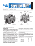
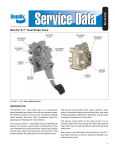
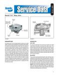
SD-03-1061A
®
Bendix® R-8P™ Pressure Equalizing Pilot Relay Valve
SPRING
COVER
PISTON
PISTON
ORIFICE
VENT
SERVICE
(CONTROL)
PORT
BODY
DELIVERY
PORTS
INLET/EXHAUST
VALVE ASSEMBLY
EXHAUST
SUPPLY PORT
DELIVERY PORT
SUPPLY PORT
FIGURE 1 - CUTAWAY AND EXTERNAL VIEW
DESCRIPTION
OPERATION
The R-8P™ pressure equalizing pilot relay valve is a device
designed to reinforce the control signal on long wheel base
towing trailers and converter dollies.
APPLICATIONS (FIG. 2)
Unlike a standard relay valve which typically has a 4 p.s.i.
crack pressure and similar differential between control and
delivery, the R-8P™ valve has a 0 p.s.i. differential.
On the converter dolly and long wheel base towing trailers,
the R-8P™ valve reinforces the service brake application
signal without the differential found in standard relay valves.
The 0 p.s.i. differential of the R-8P™ valve assures that all
trailer and dolly brakes will receive the same strength control
signal even during light brake applications.
By providing a balanced pressure signal to all trailer and
dolly brakes, the R-8P™ valve helps achieve overall vehicle
brake balance and stability. The R-8P™ valve also helps
improve brake lining wear balance on combination vehicles
by causing even the most distant brake to contribute its
share of braking effort.
When a service brake application is made, air delivered from
the brake valve enters the service port of the R-8P™ valve.
As air pressure fills the space above the piston, it begins to
force the piston down. Because of the spring force above
the piston, the piston exhaust seat is already in contact
with the inlet/exhaust valve, sealing off the exhaust. As the
piston begins to move downward it forces the inlet/exhaust
valve off the inlet seat, allowing air from the reservoir to be
delivered out the delivery ports of the R-8P™ valve in direct
proportion to the pressure received at the service port.
Any differential between service and delivery pressure caused
by friction or resistance to the movement of the piston
(commonly called crack pressure and normally in the range
of 2 to 4 p.s.i.) is eliminated due to passage of air through
the orifice in the piston.
1
R-8P™
VALVE
BRAKE
VALVE
SPRING
PISTON
ORIFICE
PISTON
R-8P™
VALVE
SPRING
PISTON
BRAKE
VALVE
PISTON
ORIFICE
SERVICE
SUPPLY
RESERVOIR
SERVICE
SUPPLY
RELAY
VALVE
INLET/EXHAUST
VALVE ASSEMBLY
SERVICE
BRAKES
VENT
DELIVERY
FIGURE 2 - OPERATIONAL VIEW OF APPLICATION
BALANCE (FIG. 3)
The air pressure being delivered by the open inlet valve also
is effective on the bottom area of the R-8P™ valve relay piston.
When air pressure beneath the piston equals the service air
pressure on top of the piston, the piston lifts slightly and the
inlet/exhaust valve is returned to the inlet seat. The exhaust
remains closed as the delivery pressure balances with the
service line pressure. Balancing of the pressure above and
below the piston through the orifice of the R-8P™ valve piston
assures that the service and delivery pressures are equal
and 0 p.s.i. differential exists. As delivered air pressure to
the R-8P™ valve service port is changed, the valve reacts,
holding the desired application pressure.
EXHAUST
RELAY
VALVE
PREVENTIVE MAINTENANCE
Important: Review the Bendix Warranty Policy before
performing any intrusive maintenance procedures. A warranty
may be voided if intrusive maintenance is performed during
the warranty period.
2
SERVICE
BRAKES
RESERVOIR
INLET/EXHAUST
VALVE ASSEMBLY
DELIVERY
FIGURE 3 - OPERATIONAL VIEW OF BALANCED POSITION
R-8P™
VALVE
SPRING
PISTON
BRAKE
VALVE
PISTON
ORIFICE
SERVICE
SUPPLY
EXHAUST
EXHAUST OR RELEASE (FIG. 4)
When air pressure is released from the service port and air
pressure in the cavity above the piston of the R-8P™ valve is
exhausted, air pressure beneath the piston lifts it upward,
further seating the inlet/exhaust valve against the inlet seat.
Raising the exhaust seat of the piston off the inlet/exhaust
valve, opens the exhaust. This allows the delivery air pressure
to rapidly exhaust to atmosphere. As air pressure under the
piston drops, the spring force above the piston will push the
piston downward, once again placing the exhaust seat of
the piston in contact with the inlet/exhaust valve. Any pressure
remaining under the piston will pass through the piston orifice
and be exhausted at the brake valve.
VENT
RESERVOIR
INLET/EXHAUST
VALVE ASSEMBLY
RELAY
VALVE
SERVICE
BRAKES
DELIVERY
FIGURE 4 - OPERATIONAL VIEW OF RELEASE
No two vehicles operate under identical conditions, as a
result, maintenance intervals may vary. Experience is a
valuable guide in determining the best maintenance interval
for air brake system components. At a minimum, the valve
should be inspected every 6 months or 1500 operating hours,
whichever comes first, for proper operation. Should the valve
not meet the elements of the operational tests noted in this
document, further investigation and service of the valve may
be required.
CONTROL TO
SECOND TRAILER
CONTROL FROM
TOWING TRAILER
R-8P™
RELAY VALVE
SC-1™ SINGLE
CHECK VALVE
RE-6™ RELAY
EMERGENCY
VALVE
SUPPLY TO
SECOND TRAILER
SUPPLY FROM
TOWING
TRAILER
SV-1™
SYNCHRO VALVE
S = SUPPLY
C = CONTROL
D = DELIVERY
E = EXHAUST
EM = EMERGENCY
FIGURE 5 - SCHEMATIC OF TYPICAL DOLLY SYSTEM
OPERATION AND LEAKAGE TEST
1. Block the wheels and fully charge the air system. Adjust
the brakes.
2. Apply and release the service brakes several times and
check for prompt response of the brakes at all appropriate
wheels.
3.
3. With the air system fully charged, apply a soap solution
to the exhaust of the R-8P™ valve. Leakage of a 1" bubble
in 5 seconds is permissible.
4. Make and hold a full brake application and again apply a
soap solution to the R-8P™ valve exhaust. Leakage of a
1" bubble in 3 seconds is permissible.
5. With the brakes still applied, apply a soap solution around
the valve where the cover meets the body. No leakage at
this point is permitted. If the valve is unable to pass
these operation and leakage tests, repair or replace it
with a new or genuine Bendix remanufactured unit,
available at any authorized parts outlet.
WARNING! PLEASE READ AND FOLLOW
THESE INSTRUCTIONS TO AVOID
PERSONAL INJURY OR DEATH:
4.
5.
6.
7.
When working on or around a vehicle, the following
general precautions should be observed at all times.
1. Park the vehicle on a level surface, apply the
parking brakes, and always block the wheels.
Always wear safety glasses.
2. Stop the engine and remove ignition key when
working under or around the vehicle. When
working in the engine compartment, the engine
8.
should be shut off and the ignition key should be
removed. Where circumstances require that the
engine be in operation, EXTREME CAUTION should
be used to prevent personal injury resulting from
contact with moving, rotating, leaking, heated or
electrically charged components.
Do not attempt to install, remove, disassemble or
assemble a component until you have read and
thoroughly understand the recommended
procedures. Use only the proper tools and observe
all precautions pertaining to use of those tools.
If the work is being performed on the vehicle’s air
brake system, or any auxiliary pressurized air
systems, make certain to drain the air pressure from
all reservoirs before beginning ANY work on the
vehicle. If the vehicle is equipped with an AD-IS™
air dryer system or a dryer reservoir module, be
sure to drain the purge reservoir.
Following
the
vehicle
manufacturer’s
recommended procedures, deactivate the electrical
system in a manner that safely removes all
electrical power from the vehicle.
Never exceed manufacturer’s recommended
pressures.
Never connect or disconnect a hose or line
containing pressure; it may whip. Never remove a
component or plug unless you are certain all
system pressure has been depleted.
Use only genuine Bendix ® replacement parts,
components and kits. Replacement hardware,
tubing, hose, fittings, etc. must be of equivalent
size, type and strength as original equipment and
be designed specifically for such applications and
systems.
3
6
1
PISTON
ORIFICE
9
8
2
SERVICE
(CONTROL)
PORT
3
VENT
SUPPLY
PORT
7
4
10
5
11
12
DELIVERY PORTS
EXHAUST
FIGURE 6 - CUTAWAY
9. Components with stripped threads or damaged
parts should be replaced rather than repaired. Do
not attempt repairs requiring machining or welding
unless specifically stated and approved by the
vehicle and component manufacturer.
10. Prior to returning the vehicle to service, make
certain all components and systems are restored
to their proper operating condition.
REMOVAL
1. Block or hold the vehicle by means other than the brakes.
2. Drain all air brake system reservoirs.
3. Identify, mark and disconnect all air lines from the R-8P™
pilot relay valve.
4. Remove the R-8P™ valve from its mount on the vehicle.
DISASSEMBLY OF VALVE (REFER TO FIG. 6)
1. Note and mark position of valve cover (6) to body (7).
2. Remove four 5/16"-18 hex screws and separate the cover
from the body (7).
3. Remove and discard sealing ring (3) from body (7).
4. Remove piston (8) and spring (9) from cover (6) and retain
all parts.
ASSEMBLY (REFER TO FIG. 6)
NOTE: Make certain both piston orifices are open and not
clogged. Grease all o-rings, o-ring grooves and bores
with a barium base lubricant.
1. Install diaphragm (5) and diaphragm washer (12) and
secure with screw (11). Torque screw to 15-25 inch
pounds.
2. Install inlet and exhaust valve assembly (4) in valve body
(7). Position exhaust cover assembly (10) so that all
holes are properly aligned and secure with four 10-24
screws. Torque screw to 20-30 inch pounds.
3. Install sealing ring (3) in valve body (7).
4. Install o-rings (1 and 2) on the piston (8).
5. Install spring (9) in valve cover (6) so that the large
diameter end of the spring will rest on the piston.
6. Install piston (8) (with its o-rings installed) in valve cover
(6). Note: Make certain spring (9) is centered and not
binding.
7. Install valve cover (6) on valve body (7) in same position
as marked in Step 1 of “Disassembly”. Secure the cover
to the body using four 5/16" hex head cap screws. Torque
to 120-150 inch pounds.
5. Remove and discard o-ring (2) from piston (8).
INSTALLATION
6. Remove screw (11), washer (12) and diaphragm (5) from
exhaust cover (10). Discard diaphragm (5).
1. Mount the R-8P™ valve to the vehicle using new bolts or
other hardware.
7. Remove four 10-24 screws which secure exhaust cover
(10) to body (7).
2. Connect air lines to the R-8P™ valve using identification
made during Step 3 of “Removal” instructions.
8. Remove and discard inlet exhaust assembly (4) from
body (7).
3. Perform “Operation and Leakage Checks” before placing
vehicle in service.
9. Clean all remaining parts in a cleaning solvent equivalent
to mineral spirits. Make certain all surfaces, bores and
passages are clean and dry.
4
BW1660 © 2004 Bendix Commercial Vehicle Systems LLC. All rights reserved. 3/2004 Printed in U.S.A.