1
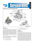
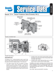
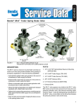
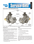
SD-03-4514
Bendix® SR-4™ Spring Brake Control Valve
#2 RESERVOIR
CHARGING
PORT
#2 RESERVOIR
CHARGING
PORT
#1
RESERVOIR
CHARGING
PORT
SERVICE PORT
SERVICE PORT
#1
RESERVOIR
CHARGING
PORT
DELIVERY
PORTS (4)
DELIVERY PORTS (4)
FIGURE 1A
TRAILER SUPPLY
PORT
TYPE 1
FIGURE 1B
TRAILER SUPPLY
PORT
TYPE 2
FIGURE 1 - SR-4™ SPRING BRAKE CONTROL VALVE TYPE 1 & TYPE 2
DESCRIPTION
The SR-4™ valve is provided in two different configurations.
Type 1 (Fig. 1A) incorporates a nipple mounted PR-3™
valve. Type 2 (Fig. 1B) has the function of the additional
PR-3™ valve integrated into the main housing. There is
no difference in the operational performance of the two
designs.
The SR-4™ trailer spring brake control valve is similar
to the SR-2™ valve. It differs in function by utilizing both
reservoirs for normal service braking but reserving sufficient
air pressure to provide the required spring brake release in
the event of a service system failure. As seen in Fig. 1, the
complete assembly includes an SR-4™ valve sub-assembly
similar in appearance to an SR-2™ valve. The SR-4™ valve
subassembly is an SR-2™ valve modified by the addition
of a check valve in the spring brake reservoir fitting which
permits air to pass from the reservoir to the spring brake
inlet valve but not in the opposite direction. AT NO TIME
SHOULD AN SR-2™ VALVE BE SUBSTITUTED FOR THE
SR-4™ VALVE SUBASSEMBLY. The SR-4™ valve may be
identified by the metal tag affixed to the cover by one of
four cap screws. Porting is as follows:
• 1/2 inch NPT or 3/4 inch NPT spring brake supply port
for reservoir mounting
• 4-3/8 inch NPT delivery ports
• 2-1/4 inch NPT reservoir charging ports
• 1-1/4 inch NPT trailer supply port
• 1-1/4 inch NPT service port (optional)
OPERATION (FIG. 2)
CHARGING
Air from the trailer supply line enters at the trailer supply port
and depresses the control piston "D", opening the spring
brake inlet valve "E". It also is conducted to the cavity under
the pressure protection piston "F". When air pressure builds
to approximately 60 p.s.i. beneath the pressure protection
piston, the piston moves against the force of the pressure
protection spring and opens the pressure protection inlet
valve. The air pressure now flows past check valve “A”
into the #2 reservoir and past check valve “B” through the
open spring brake inlet valve and into the spring brake
1
SERVICE LINE
PRESSURE
PROTECTION
INLET VALVES
PRESSURE PROTECTION
PISTON SPRINGS
PRESSURE PROTECTION
PISTON "F"
CHECK VALVE "G"
RES.
#1
ANTI-COMPOUND
LINE
PRESSURE PROTECTION
PISTON "F"
CHECK VALVE “A”
RES.
#2
CHECK VALVE “B”
SUPPLY PORT
RELAY VALVE
CHECK VALVE “C”
SPRING BRAKE
INLET VALVE "E"
ANTI-COMPOUNDING
CHECK VALVE
TRAILER SUPPLY LINE
CONTROL PISTON "D"
SPRING BRAKE
FIGURE 2 - SR-4™ VALVE CROSS-SECTIONAL SCHEMATIC
units. Air is prevented from flowing from the SR-4™ valve
into reservoir #1 by check valve "C". Air simultaneously
flows into the PR-3™ pressure protection valve, (Type 1
SR-4™ valve) or the second pressure protection piston
(Type 2 SR-4™ valve). At approximately 70 psi piston "F"
moves against the resistance of its spring, allowing air to
flow through check valve "G" and into reservoir #1.
PARK APPLICATION
To apply the trailer spring brakes, the trailer supply line
is exhausted by means of one of the cab controls. Air
pressure is removed from the control piston and the
internal pressure protection piston, closing the pressure
protection valve and the spring brake inlet valve.
SERVICE SYSTEM FAILURE
If air pressure is reduced in the service system, pressure in
the trailer supply line (and in the tractor) will be reduced until
the internal pressure protection valve closes, maintaining
50-60 p.s.i. in the trailer supply line and the tractor service
reservoir. This will maintain 50-60 p.s.i. on the control piston
which will keep the spring brakes released. At the same
time, the reduction in pressure in the tractor system will
sound the low pressure signal, alerting the driver. If the
service failure is in the #2 reservoir, the air which passes
the pressure protection valve will escape through the #2
reservoir and will not be able to resupply the #1 reservoir.
The #1 reservoir will retain full pressure because of the
pressure protection check valve and check valve “B”. This
2
reserve supply of air will provide at least one spring brake
release after a manual application. Service applications
may still be made until the air in the #1 reservoir is
exhausted.
If the service failure is in the #1 reservoir, the pressure
protection valve will close and allow air to supply the
#2 reservoir. This air will be available to release the
spring brake through check valve “B”, although service
applications may not be made.
EMERGENCY APPLICATION WITH SERVICE
SYSTEM FAILURE
To brake the trailer after a service system failure, the
remaining 55 p.s.i. pressure in the trailer supply line may
be exhausted either manually or automatically by the trailer
supply valve or parking control valve. The spring brakes are
then exhausted through the control piston and thus applied.
Sufficient pressure will be maintained in the trailer system
to release the spring brakes at least once.
ANTI-COMPOUNDING OPTION
Under certain conditions when the tractor protection valve
goes into the emergency mode during a service application,
the trailer supply line will be exhausted but some air may
be trapped in the service line, creating a service application
plus a full spring application. This creates a false park
situation and adds an extra load on the foundation brake
components. This may be prevented by adding the optional
anti-compounding piping as shown in Figs. 2 & 3.
R-12™
RELAY
VALVE
TRAILER SERVICE LINE
ANTI-COMPOUNDING
CONNECTION
SINGLE CHECK
VALVE
RES. #1
RES. #2
TRAILER SUPPLY LINE
FIGURE 3 - SR-4™ VALVE ANTI-COMPOUNDING PLUMBING
PREVENTIVE MAINTENANCE
Important: Review the Bendix Warranty Policy before
performing any intrusive maintenance procedures. A
warranty may be voided if intrusive maintenance is
performed during the warranty period.
No two vehicles operate under identical conditions, as
a result, maintenance intervals may vary. Experience is
a valuable guide in determining the best maintenance
interval for air brake system components. At a minimum,
the SR-4™ valve should be inspected every 6 months or
1500 operating hours, whichever comes first, for proper
operation. Should the SR-4™ valve not meet the elements
of the operational tests noted in this document, further
investigation and service of the valve may be required.
SERVICE AND LEAKAGE TESTS
Check the tractor dash gauge against a test gauge known
to be accurate prior to performing these tests. Connect
the tractor air lines to the trailer on which the SR-4™ trailer
spring brake valve is to be tested. Block all wheels or hold
both vehicles by a means other than air brakes.
1. Install two separate test gauges or one dual test gauge
with one line to the #1 reservoir and the other line to the
#2 reservoir. Build the tractor and trailer to full system
pressure by placing the trailer supply valve in the charge
position and the parking control valve in the "brakes
released" position.
Note:
As system pressure reaches approximately 60
p.s.i., the #2 reservoir and the spring brakes
should build up to approximately 60 p.s.i. before
the #1 reservoir begins to charge (see Fig. 3).
When full system pressure has been reached and
the spring brakes fully released, it is acceptable
to have a slightly lower pressure reading in the
service reservoirs than is registered on the dash
gauge. Apply a soap solution to the exhaust port
and the vent. Leakage of a 1" bubble in 5 seconds
is permissible.
2. Place the trailer supply valve in the exhaust position;
the spring brakes should apply. Disconnect the trailer
supply line and soap the hose coupling to check
for leaks. A 1" bubble in not less than 5 seconds is
permissible.
3. Reconnect the trailer supply hose coupling and recharge
the trailer system. The spring brakes should release.
Shut off the engine, leaving the ignition on and open the
drain cock on the #1 reservoir. The tractor air system
should bleed down to approximately 55 p.s.i. with low
pressure, indication occurring at or before 60 p.s.i. The
#2 reservoir on the trailer should also bleed down to
approximately 55 p.s.i. but the spring brakes on tractor
and trailer should remain released. After the system is
stabilized, leakage at the open drain cock in the trailer
should not exceed a 1" bubble in 5 seconds.
3
4. Close the drain cock on the trailer #1 reservoir, recharge
the system, stop the engine and open the drain cock
on the #2 reservoir. Again, the tractor air system
should bleed down to approximately 45 p.s.i., but the
#1 reservoir on the trailer should remain fully charged.
The spring brakes should remain released on both
the tractor and trailer. Leakage at the open drain cock
should not exceed a 1" bubble in 5 seconds. As this
test is completed, close the drain cock on the trailer
reservoir.
5. If the SR-4™ spring brake valve does not function
as described above or leakage is excessive, it is
recommended that it be repaired or replaced with a
genuine Bendix service replacement valve.
WARNING! PLEASE READ AND FOLLOW
THESE INSTRUCTIONS TO AVOID PERSONAL
INJURY OR DEATH:
When working on or around a vehicle, the following
general precautions should be observed at all times.
1. Park the vehicle on a level surface, apply the
parking brakes, and always block the wheels.
Always wear safety glasses.
2. Stop the engine and remove ignition key when
working under or around the vehicle. When
working in the engine compartment, the engine
should be shut off and the ignition key should be
removed. Where circumstances require that the
engine be in operation, EXTREME CAUTION should
be used to prevent personal injury resulting from
contact with moving, rotating, leaking, heated or
electrically charged components.
3. Do not attempt to install, remove, disassemble
or assemble a component until you have read
and thoroughly understand the recommended
procedures. Use only the proper tools and observe
all precautions pertaining to use of those tools.
4. If the work is being performed on the vehicle’s
air brake system, or any auxiliary pressurized air
systems, make certain to drain the air pressure
from all reservoirs before beginning ANY work
on the vehicle. If the vehicle is equipped with an
AD-IS® air dryer system or a dryer reservoir module,
be sure to drain the purge reservoir.
5. Following the vehicle manufacturer’s recommended
procedures, deactivate the electrical system in a
manner that safely removes all electrical power
from the vehicle.
6. Never exceed manufacturer’s recommended
pressures.
7. Never connect or disconnect a hose or line
containing pressure; it may whip. Never remove
a component or plug unless you are certain all
system pressure has been depleted.
4
8. Use only genuine Bendix® replacement parts,
components and kits. Replacement hardware,
tubing, hose, fittings, etc. must be of equivalent
size, type and strength as original equipment and
be designed specifically for such applications and
systems.
9. Components with stripped threads or damaged
parts should be replaced rather than repaired. Do
not attempt repairs requiring machining or welding
unless specifically stated and approved by the
vehicle and component manufacturer.
10. Prior to returning the vehicle to service, make
certain all components and systems are restored
to their proper operating condition.
11. For vehicles with Antilock Traction Control (ATC),
the ATC function must be disabled (ATC indicator
lamp should be ON) prior to performing any vehicle
maintenance where one or more wheels on a drive
axle are lifted off the ground and moving.
REMOVAL OF VALVE FROM VEHICLE
1. Check the vehicle wheels and drain all air system
reservoirs completely.
2. Disconnect all supply, delivery and exhaust lines
at the trailer spring brake valve. NOTE: Mark all air
lines and their relation to the spring brake valve for
reconnection.
3. Remove the spring brake valve from the trailer #1
reservoir.
PR-3™ VALVE REMOVAL AND TEST
(TYPE 1 SR-4™ VALVE)
1. Remove the PR-3 ™ valve from the SR-4 ™ valve
assembly.
2. Apply 50 p.s.i. air pressure at the supply port and apply
a soap solution to the delivery port. Leakage of a 1"
bubble in 3 seconds is permissible.
3. Apply 100 p.s.i. air pressure at the delivery port.
Apply a soap solution to the supply port. No leakage
permissible.
4. If the PR-3™ valve does not function as described above
or leakage is excessive, it is suggested it be exchanged
or replaced at the nearest Bendix distributor. The PR-3™
valve is not considered as serviceable internally. If
the PR-3™ valve is disassembled, DO NOT MIX the
PR-3™ valve parts with similar looking parts in the main
assembly.
1
CHECK
VALVE “A”
21
2
20
CHECK
VALVE “B”
21
3
5
20
4
15
6
14
7
16
9
CHECK
VALVE “C”
26
METAL I.D.
TAG
11
10
25
12
24
8
13
23
EXHAUST
PORT
(17 - SCREW)
(18 - WASHER)
(19 - DIAPHRAGM)
IF EQUIPPED
FIGURE 4
SR-4™ VALVE DISASSEMBLY
(TYPE 1 REFER TO FIG. 4)
REMOVAL AND DISASSEMBLY OF THE PRESSURE
PROTECTION PISTON (FIG. 4)
7. Remove the reservoir port fitting (13) from the valve
body.
1. Remove the four round head machine screws which
secure the spring retainer (1) to the valve body. NOTE:
Take caution when removing the spring retainer as it is
spring loaded.
8. Remove the o-ring (14) from the reservoir fitting.
2. Remove the spring (2) and pressure protection piston
assembly (3).
3. Remove the inlet valve (4) from the piston stem and
o-rings (5) from the piston. NOTE: Do not attempt to
remove the retaining ring and stem from the piston.
REMOVAL AND DISASSEMBLY OF THE CONTROL
PISTON
4. Note and mark the position of the control piston cover
(6) on the valve body. Remove the four 1/4 inch -20
hex head cap screws and lock washers which retain
the cover to the body.
5. Remove the cover, seal ring (7), control piston assembly,
and spring (8) from the valve body.
6. From the control piston (9) remove the three o-rings
(10, 11 & 12).
REMOVAL OF CHECK VALVE “C”
9. Place the reservoir fitting (13) in a vise and remove
retaining ring (23), valve retainer (24), spring (25) and
check valve (26).
10. Remove the inlet valve spring (15), and inlet and
exhaust valve (16).
11. If so equipped, remove the screw (17), washer (18) and
diaphragm (19) from the exhaust port.
REMOVAL OF THE TWO SINGLE CHECK VALVES “A”
& “B”
NOTE: Figures 2 and 4 show check valve “A” and check
valve “B” out of position for illustration.
12. Remove the two 3/8 inch socket head pipe plugs which
retain the two single check valves in the body.
13. Remove the two check valve springs (20), and rubber
check valves (21).
5
1
2
3
3
BODY
4
13
END CAP
EXHAUST
END CAP
12
4
11
4
5
10
9
END CAP
6
7
4
14
8
EXHAUST
FIGURE 5 INSETS - VIEWS OF LOCATION OF THE FOUR CHECK VALVE ASSEMBLIES (4)
DISASSEMBLY TYPE 2 SR-4™ VALVE
(REFER TO FIG. 5)
1. Remove and save the eight cap screws holding the two
spring retainers in place. Remove the spring retainers
and remove the springs (1 & 2) taking note of the
differences and from which cavity it was removed. (One
is color coded green the other white.)
2. With a pair of pliers, grasp the raised surface of the two
piston assemblies (3) and remove them from the valve
body housing.
3. Refer to Fig. 5. With a 5/16 inch Allen Wrench, remove
the four 3/8 inch pipe plugs from the SR-4™ valve.
(Three are in the main body and one is in the end cap.)
Trailers without anti-compounding feature will not have
a check valve in the end cover. Remove the four check
valve assemblies (4), one under each of the 3/8 inch
pipe plugs.
4. Note and mark the position of the end cover to the
body. Remove the four cap screws that retain the end
cover. Remove the end cover from the body. Remove
the sealing ring (5) from the end cover.
5. Remove the large piston from its bore by grasping the
web with a pair of pliers and pulling. Remove the spring
(6) from the base of the bore. Remove the o-rings (7 &
8) from the piston.
6
6. Remove the check valve assembly from the main body
by lightly clamping the body in a vise and turning the
check valve assembly counterclockwise with a 1-1/4
inch end wrench. Remove the spring (9) and the inlet/
exhaust valve (10) from the housing. Remove the o-ring
(11) from the O.D. of the check valve assembly.
7. With a pair of I.D. snap ring pliers, remove the snap
ring in the end of the check valve assembly. Remove
the spring seat, the conical spring (12) and the check
valve (13).
8. Using a Phillips head screwdriver, remove the Phillips
head screw and the diaphragm washer from the
exhaust port of the SR-4™ valve body. Remove the
diaphragm (14).
CLEANING AND INSPECTION
1. Using mineral spirits or an equivalent solvent, clean
and thoroughly dry all metal parts.
2. Inspect the interior and exterior or all metal parts that
will be reused for severe corrosion, pitting or cracks.
Superficial corrosion and/or pitting on the exterior
portion of the valve is acceptable.
3. Inspect the bores of the valve housing for deep scuffing
or gouges.
ASSEMBLY
ASSEMBLY - CHECK VALVES “A” AND “B”
Prior to reassembling the SR-4™ valve, lubricate all o-rings,
o-ring grooves, piston bores, and metal to metal moving
surfaces with Bendix silicone lubricant BW-650-M piece
number 291126.
1. Twist the check valves (21) into the springs (20) and
place in their respective bores, and install the socket
head pipe plugs. Torque to 140-170 inch pounds.
IMPORTANT NOTE: When pipe thread sealant is used
during assembly and reinstallation, particular care
should be taken to assure that this material does
not get into the valve itself. Pipe sealant should be
applied beginning with the second thread back from
the end.
1. If so equipped, position the diaphragm (19), washer
(18) and screw (17) in the control piston exhaust port.
Torque the screw from 15 to 25 inch pounds.
ASSEMBLY
TYPE 1 SR-4™ VALVE (REFER TO FIG. 4)
RESERVOIR FITTING (CHECK VALVE “C”) AND
INLET EXHAUST VALVE
1. Place reservoir fitting (13) in a vise, pipe threads
down.
2. Insert the check valve (26), check valve spring (25),
valve retainers (24), and retaining ring (23).
3. Install the flat inlet exhaust valve into the valve body.
NOTE: The flat side of the valve with the four ears protruding
rests against the inlet and exhaust seat.
4. Place the inlet exhaust valve spring (15) in positions
on the inlet exhaust valve.
5. Properly align the reservoir fitting assembly (13) and
install in body. Torque to 200 to 300 inch pounds.
ASSEMBLY - CONTROL PISTON AND COVER
6. Install the three o-rings (10, 11 & 12) on the control
piston (9).
7. Position the control piston return spring (8) in the body
and install the control piston.
8. Install the seal ring (7) in the groove on the control
piston cover and assemble the cover to the body.
Tighten the cap screw to 40-60 inch pounds.
ASSEMBLY - PRESSURE PROTECTION VALVE
9. Install the o-ring (5) on the pressure protection piston
(3) and the rubber inlet exhaust valve over the stem.
NOTE: Light lubrication of the piston stem will facilitate
the rubber valve installation.
10. Install the pressure protection piston assembly in the
valve body and position the pressure protection spring
on the piston.
11. Position the spring retainer on top of the pressure
protection piston assembly and secure with the four
round head machine screws. Torque to 20-30 inch
pounds.
ASSEMBLY - EXHAUST CHECK VALVE
ASSEMBLY TYPE 2 SR-4™ VALVE (REFER TO
FIG. 5)
1. Install diaphragm (14) into the exhaust port of the SR-4™
valve. Retain with the diaphragm washer and Phillips
head screw. Tighten securely.
2. Twist the conical spring (12) onto the spring seat and
the opposite end onto the check valve (13), install this
subassembly into the check valve housing, depress
the spring seat and install the snap ring making sure it
is fully seated in its groove.
3. Install the inlet/exhaust valve (10) into the RES-1 port
making sure the flat side of the valve is against the inlet
seat. Install spring (9) into the valve making sure it is
installed over the rubber protrusion of the valve (10).
4. Install the o-ring (11) into the groove on the check valve
assembly. Thread the check valve assembly into the
RES-1 port. Lightly clamp the SR-4™ valve body in
a vise and using a 1-1/4 inch end wrench torque to
150-400 inch pounds.
5. Place the spring (6) into the large bore of the SR-4™
valve body making sure it is seated in the base of the
bore. Install the o-ring (7 & 8) onto the piston. Place
the piston into the housing with the small end inside of
the spring (6).
6. Install the sealing ring (5) into its groove on the end
cover. Install the end cover over the piston, installed in
Step 5, with the trailer supply port oriented towards the
exhaust port. Retain with the four 1/4 inch cap screws,
torque to 30-60 inch pounds.
7. Refer to Fig. 2. Install the four check valve assemblies
(4) into the cavities of the SR-4™ valve and retain
with the 3/8 inch pipe plugs. Removed in Step 3 of
“Disassembly”. Apply a thread sealant or Teflon tape
to the threads of the pipe plugs and torque to 130-170
inch pounds.
8. Install the two piston assemblies (3) into their cavities,
place the spring (1 & 2) over the bosses of the piston
assemblies. CAUTION: THE SPRING COLOR CODED
WHITE MUST BE INSTALLED ON THE PISTON
CLOSEST TO THE END COVER AND THE GREEN
COLOR CODED SPRING ON THE PISTON AWAY
FROM THE END COVER. Place the spring retainers
over the springs and retain with the eight #10 cap
screws. Torque to 20-30 inch pounds.
7
INSTALLATION
OPERATING AND LEAKAGE TESTS
1. Clean air lines connecting to valve.
Check the tractor dash gauge against a test gauge known
to be accurate prior to performing these tests. Connect
the tractor air lines to the trailer on which the SR-4™ trailer
spring brake valve is to be tested. Block all wheels, or
otherwise hold both vehicles by a means other than air
brakes during these tests.
2. Inspect all lines and/or hoses for damage and replace
as necessary.
3. Install valve and tighten.
4. Connect air lines to valve (plug any unused ports).
5. Test valve in accordance with the “Operating and
Leakage Tests”.
TESTING THE REBUILT SR-4™ VALVE
Test the rebuilt SR-4™ valve as explained in “Service and
Leakage Tests”.
BW1571 © 2007 Bendix Commercial Vehicle Systems LLC. All rights reserved. 7/2007 Printed in U.S.A.
8