1
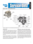
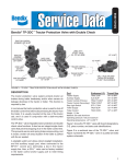
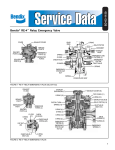
SD-03-1061
®
Bendix® R-8™ Relay Valve
COVER
ASSY.
RELAY
PISTON
ASSY.
1/4 P.T.
SERVICE
3/4 P.T.
SUPPLY
1/2 P.T.
DELIVERY
EXHAUST COVER
SCREW
QUICK
RELEASE
DIAPHRAGM
O-RING
PISTON
RETURN
SPRING
SEALING
RING
INLET &
EXHAUST
VALVE
CAP
NUT
SEALING
RING
O-RING
EXHAUST
COVER
WASHER
FIGURE 1 - EXTERIOR
SCREW
DIAPHRAGM
FIGURE 2 - SECTIONAL
DESCRIPTION
GENERAL OPERATION
The relay valve in an air brake system functions as a relay
station to speed up the application and release of the brakes.
The valve is normally mounted in the proximity to the
chamber it serves. The valve operates as a remote controlled
brake valve that delivers or releases air to the chambers in
response to the control air delivered to it from the control
point.
The rapid reaction of the R-8™ valve to changes in control
pressures is in part due to the relatively small volume of air
required between the valve cover and the relay piston. The
area of the relay piston and the presence of the quick release,
anti-compound feature also contribute greatly to the fast
application and release of the emergency and parking brakes.
The R-8™ relay valve is designed for either frame or reservoir
mounting. Remote mounted valves generally have one or
two 3/4" supply ports. The reservoir mounted configuration
has an additional 3/4" port through the body mounting flange.
Three delivery ports with various size pipe threads are
provided for piping versatility. A single 1/4" service port is
located in the cover which can be rotated to 90° increments.
The R-8™ valve incorporates a unique, quick release and
anti-compounding feature located above the service port in
the cover. With the anti-compounding feature not in use,
an exhaust cover is installed. When the anti-compounding
feature is used, removal of the exhaust cover exposes a
1/8" pipe thread balance port. All ports on the valve are
identified.
APPLYING
Air pressure entering the service port moves the flexible
diaphragm, closing off the exhaust passage of the quick
release. Air also flows around the edge of the diaphragm
and into the cavity between the cover and the top of the
relay piston. Air pressure acting on the surface of the piston
forces it down. The exhaust valve seat moves down with the
piston and seats on the inner or exhaust portion of the inlet
and exhaust valve, sealing off the exhaust passage. At the
same time the outer or inlet port of the inlet and exhaust
valve moves off its seat, permitting supply air to flow from
the reservoir past the open inlet valve and out the delivery
port.
1
BALANCED
OPERATING AND LEAKAGE TEST
The air pressure being delivered by the open inlet valve also
is effective on the bottom area of the relay piston. When this
delivery air pressure beneath the piston equals the service
air pressure above, the piston moves up slightly and the
inlet spring returns the inlet valve to its seat. The exhaust
remains closed as service line pressure balances delivery
pressure.
1. Check the wheels and fully charge the air system.
Adjust the brakes.
RELEASING
When air pressure is exhausted from the service port, the
diaphragm in the quick release moves, blocking the service
inlet and opening the exhaust of the quick release allowing
the air that was acting on the relay piston to be exhausted
at the quick release. When the air above the relay piston is
exhausted, the air beneath the piston will lift the piston and
the exhaust seat moves off the exhaust valve exposing the
exhaust passage to atmosphere. With the exhaust passage
open, the air pressure in the emergency or park actuators
exhausts out the exhaust port to atmosphere.
ANTI-COMPOUNDING (SIMULTANEOUS
SERVICE AND PARK APPLICATION)
In those applications where the R-8™ relay valve is used to
control spring brake chambers, the anti-compound feature
may be utilized. With the anti-compound feature of the R-8™
valve connected, a service application made while the vehicle
is parked is countered by a release of the parking brakes.
To utilize this feature, the exhaust cover of the quick release
portion of the R-8™ valve is removed and a line is installed
which is connected to the delivery of the service brake valve
or relay valve. With no air pressure at the service port of the
R-8™ valve, the parking brakes are applied. If a service brake
application is made, air from the service brake valve enters
the exhaust port of the quick release on the R-8™ valve and
moves the diaphragm, blocking the service port. Air then
proceeds into the cavity above the relay piston, forces the
piston down, closing the exhaust and opening the inlet to
deliver air to the spring brake cavity as described under the
section of this manual entitled APPLYING.
PREVENTIVE MAINTENANCE
Important: Review the Bendix Warranty Policy before
performing any intrusive maintenance procedures. A warranty
may be voided if intrusive maintenance is performed during
the warranty period.
No two vehicles operate under identical conditions, as a
result, maintenance intervals may vary. Experience is a
valuable guide in determining the best maintenance interval
for air brake system components. At a minimum, the valve
should be inspected every 6 months or 1500 operating hours,
whichever comes first, for proper operation. Should the valve
not meet the elements of the operational tests noted in this
document, further investigation and service of the valve may
be required.
2
2. Apply and release the parking brakes several times and
check for prompt response of the brakes at all
appropriate wheels.
3. With the park control valve in the brakes “applied position”,
coat the exhaust port with a soap solution to check for
inlet valve and o-ring leakage; a 1" bubble in 5 seconds
is permissible.
4. Place the park control valve in the “brakes released”
position and again check at the exhaust port for leakage
of the exhaust valve; a 1" bubble in 3 seconds is
permissible. Apply soap solution around the valve where
the cover joins the body to check for seal ring leakage;
no leakage permitted.
5. With the park control still in the brakes released position,
apply soap solution to the quick release exhaust port to
check the diaphragm exhaust seat; a 1" bubble in 3
seconds is permitted.
(NOTE: If the anti-compound feature is in use, the line
attached to the R-8™ valve quick release exhaust
must be disconnected to perform this test.)
If the valve does not function as described above, or if
leakage is excessive, it is recommended that the valve
be replaced with a new or remanufactured unit, or
repaired with genuine Bendix parts available at Bendix
outlets.
REMOVING
1. Block or hold the vehicle by means other than the
brakes.
2. Drain all air brake system reservoirs.
3. Identify, mark, and disconnect all air lines from the R-8™
relay valve.
4. Remove the R-8™ valve from its mount on the vehicle.
(NOTE: The inlet and exhaust valve assembly, (generally
referred to as the insert) can be easily removed and
replaced. Remove the exhaust cover cap screws
and cover. Normally the insert can be removed
without disturbing the valve mounting or connecting
lines. CAUTION: DRAIN ALL RESERVOIRS
BEFORE ATTEMPTING TO REMOVE THE
INSERT.
DISASSEMBLY
1. Prior to disassembly of the R-8 ™ valve, mark the
relationship of the cover and body to facilitate assembly.
2. Remove the four 5/16" hex head cap screws and
lockwashers that secure the cover to the body and
separate the valve halves: remove the piston spring.
(NOTE: The standard R-8™ valve does not employ a piston
return spring. However, it is optionally used in some
values.)
3. Remove the sealing ring from the groove in the body.
4. Remove the relay piston and o-ring from the cover.
5. Remove the service port cap nut from the cover and
remove the cap nut o-ring from the cap nut.
6. Remove the quick release diaphragm from the service
port.
7. If the exhaust port of the quick release is protected with
a cover, remove the cover by removal of the #10-24 phillips
screw.
8. Remove the #10-24 phillips screw that secure the
exhaust diaphragm and washer to the exhaust cover.
9. Remove the four #10-24 phillips head screws that secure
the exhaust cover to the body.
10. Remove the inlet/exhaust valve insert from the body.
(NOTE: If a new inlet/exhaust value insert is to be installed,
omit step 11.)
11. Disassemble the insert by removing the retaining ring
and separating; the special washer, o-ring retainer and
o-rings, the valve spring, valve retainer and the inlet
and exhaust valve.
CLEANING AND INSPECTION
1. Wash all metal parts in mineral spirits and dry them
thoroughly.
(NOTE: When rebuilding the R-8™ valve, all springs and all
rubber parts should be replaced.)
2. Inspect all metal parts for deterioration and wear, as
evidenced by scratches, scoring and corrosion.
3. Inspect the exhaust valve seat on the relay piston for
nicks and scratches which could cause excessive
leakage.
4. Inspect the inlet valve seat in the body for scratches
and nicks, which could cause excessive leakage.
(NOTE: All torques specified in this manual are assembly
torques and can be expected to fall off, after
assembly. Do not retorque after initial assembly
torques fall. To convert inch pounds of torque to foot
pounds of torque, divide inch pounds by 12.
Inch Pounds
12
=Foot Pounds
To convert foot pounds of torque to inch pounds of torque
multiply foot pounds by 12.
Foot pounds x 12 = Inch pounds
For assembly, hand wrenches are recommended.
1. Install the o-ring on the service port cap nut.
2. Place the quick release diaphragm in the R-8™ valve
cover: be certain it is positioned down between the guide
ribs in the cover. Install the service port cap nut. Torque
to approximately 150 inch pounds.
3. If the quick release exhaust port was protected with an
exhaust cover, install the cover using one of the #10-24
phillips head screws. Torque to approx. 15-25 inch
pounds.
4. Install o-ring on the relay piston and install the piston in
the cover.
(NOTE: If a new inlet/exhaust valve insert is used, omit steps
5-8.)
5. Place the inlet/exhaust valve, rubber side down, on a
clean flat surface. Install the valve retainer then the spring
on the inlet exhaust valve.
6. Install the two o-rings in their appropriate grooves in
the o-ring retainer and place the special washer over
the o-rings.
7. While holding the o-ring retainer and special washer
together, install them over the inlet and exhaust valve,
making sure the inlet valve spring is bearing on the
o-ring retainer
5. Inspect the exhaust seat of the quick release diaphragm
in the R-8™ valve cover and make sure all internal air
passages in this area are open and clean and free of
nicks and scratches.
8. Install the retainer ring in the groove around the inlet
and exhaust valve while holding the assembly
compressed.
6. Replace all parts not considered serviceable during
these inspections and all springs and rubber parts. Use
only genuine Bendix replacement parts which are
available from Bendix outlets.
10. Place the exhaust cover on the body and secure it using
the four #10-24 phillips head screws. Torque the screws
to 20-30 inch pounds.
ASSEMBLY
Prior to reassembling the R-8™ relay valve, lubricate all
o-rings, o-ring grooves, piston bores and metal to metal
moving surfaces with Dow Corning Silicone 55-M Pneumatic
Grease (Bendix pc. 291126).
9. Install the inlet/exhaust valve insert in the body bore.
11. Place the exhaust diaphragm on the exhaust cover and
secure it using the diaphragm washer and the remaining
#10-24 phillips head screw. Torque the screw to
approximately 5-10 inch pounds.
12. Prior to assembling the cover to the body note the mark
made during disassembly to obtain the proper cover
body relationship.
3
13. Place the piston return spring (if so equipped) on the
piston within the cover.
14. Install the seal ring in the groove of the R-8™ valve body
and join the two valve halves together.
15. Secure the body to the cover using the four 5/16-18 hex
head cap screws. Torque to approximately 80-120 inch
pounds.
INSTALLING
Prior to installing the R-8™ valve on the vehicle, all connecting
air lines should be inspected for kinks, cuts, chafing and
deterioration. Repair or replace as necessary.
1. Mount the R-8™ relay valve securely.
2. Connect all air lines to the proper ports, using the
identification markings of the lines made before valve
was removed.
3. Test all reconnected air line fittings for leakage.
4. Test valve as outlined in “operating and leakage tests”
section.
WARNING! PLEASE READ AND FOLLOW
THESE INSTRUCTIONS TO AVOID
PERSONAL INJURY OR DEATH:
When working on or around a vehicle, the following
general precautions should be observed at all times.
1. Park the vehicle on a level surface, apply the
parking brakes, and always block the wheels.
Always wear safety glasses.
2. Stop the engine and remove ignition key when
working under or around the vehicle. When
working in the engine compartment, the engine
should be shut off and the ignition key should be
removed. Where circumstances require that the
engine be in operation, EXTREME CAUTION should
be used to prevent personal injury resulting from
contact with moving, rotating, leaking, heated or
electrically charged components.
4
3. Do not attempt to install, remove, disassemble or
assemble a component until you have read and
thoroughly understand the recommended
procedures. Use only the proper tools and observe
all precautions pertaining to use of those tools.
4. If the work is being performed on the vehicle’s air
brake system, or any auxiliary pressurized air
systems, make certain to drain the air pressure from
all reservoirs before beginning ANY work on the
vehicle. If the vehicle is equipped with an AD-IS™
air dryer system or a dryer reservoir module, be
sure to drain the purge reservoir.
5. Following
the
vehicle
manufacturer’s
recommended procedures, deactivate the electrical
system in a manner that safely removes all
electrical power from the vehicle.
6. Never exceed manufacturer’s recommended
pressures.
7. Never connect or disconnect a hose or line
containing pressure; it may whip. Never remove a
component or plug unless you are certain all
system pressure has been depleted.
8. Use only genuine Bendix ® replacement parts,
components and kits. Replacement hardware,
tubing, hose, fittings, etc. must be of equivalent
size, type and strength as original equipment and
be designed specifically for such applications and
systems.
9. Components with stripped threads or damaged
parts should be replaced rather than repaired. Do
not attempt repairs requiring machining or welding
unless specifically stated and approved by the
vehicle and component manufacturer.
10. Prior to returning the vehicle to service, make
certain all components and systems are restored
to their proper operating condition.
BW1569 © 2004 Bendix Commercial Vehicle Systems LLC. All rights reserved. 3/2004 Printed in U.S.A.