1
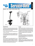
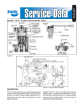
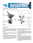
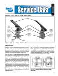
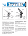
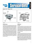
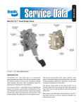
SD-03-4503
®
Bendix® TC-4™ Modulating Control Valve
EXHAUST
PORT
DELIVERY
PORT
DELIVERY
PORT
FIGURE 1
SUPPLY PORT
TC-2™ VALVE
TP-2™
VALVE
COUPLINGS
TW-1™ VALVE
TC-2™ VALVE
DS-1
™
SV-1
VALVE
GAUGE
BRAKE
CHAMBERS
TRAILER
SERVICE
TRAILER
EMERGENCY
MANIFOLD
SPRING
BRAKES
E-3™ BRAKE
VALVE
RELAY
VALVE
QR-1™
VALVE
COMPRESSOR
GOVERNOR
QR-1™
VALVE
PARKING &
EMERGENCY
RESERVOIR
SINGLE CHECK
VALVE
SAFETY VALVE
SUPPLY
RESERVOIR
SERVICE
RESERVOIR
FIGURE 2
DRAIN COCK
DRAIN
COCK
SINGLE CHECK
VALVE
TYPICAL
PIPING
DIAGRAM
7 LEVER
PIN 9
8 TORSION SPRING
O-RING 15
PLUNGER 10
PISTON RETURN SPRING 14
SHIM
12 GRADUATING SPRING
MACHINE SCREW
16 O-RING
6 DISC
13 PISTON
5 LOCKING
BUTTON
BODY
VALVE 4
VALVE SPRING 5
CAP NUT SEALING RING 2
CAP NUT 1
FIGURE 3
2
DESCRIPTION
PREVENTIVE MAINTENANCE
The TC-4™ modulating control valve is a cam operated,
graduating type control valve. The valve is used to control
the application and release of spring brake actuators, and is
generally mounted in the cab within easy reach of the driver.
Important: Review the Bendix Warranty Policy before
performing any intrusive maintenance procedures. A warranty
may be voided if intrusive maintenance is performed during
the warranty period.
Modulated control of the emergency brakes (spring brakes)
is effected by moving the valve’s spring loaded lever. Moving
the lever against the resistance of the spring applies the
brakes and, allowing the valve handle to return, releases the
brakes.
No two vehicles operate under identical conditions, as a
result, maintenance intervals may vary. Experience is a
valuable guide in determining the best maintenance interval
for air brake system components. At a minimum, the TC-4™
valve should be inspected every 6 months or 1500 operating
hours, whichever comes first, for proper operation. Should
the TC-4™ valve not meet the elements of the operational
tests noted in this document, further investigation and service
of the valve may be required.
When the valve is used for parking, the locking button is
moved into the locked position after the handle has been
moved to the “Brakes Applied” position. The lever is now
mechanically locked in position. To release the lever, the
lever is slightly depressed, the lock button moved out of the
locked position and the lever returned to the “Brakes
Released” position.
Porting consists of one (1) supply port, two (2) delivery and
two (2) exhaust ports.
OPERATION
Reference Figure 2, the TC-4™ valve is generally used in
conjunction with a relay valve to control the application and
release of the spring brakes. In a typical system, the TC-4™
valve and the relay valve receive supply air from the
emergency/parking reservoir.
RELEASED POSITION (Spring Brakes Released)
In the normal run position, air enters the supply port of the
TC-4™ valve, flows by the open inlet valve and out the delivery
port. Air flows to the service (control) port of the relay valve
causing the relay valve to deliver air to the spring brakes,
holding them in the released position.
APPLY POSITION (Spring Brakes Applied)
Moving the lever to the apply position allows the inlet valve
to close and the exhaust passage to open. This allows the
air being delivered to the service (control) port of the relay
valve to exhaust to atmosphere (through the exhaust of the
foot brake valve). With air exhausted from the service
(control) port of the relay valve, the relay valve responds,
exhausting the air from the spring brakes (allowing the brakes
to apply).
With sufficient air pressure in the emergency/parking
reservoir, modulation of the spring brake application is
possible; the amount of braking force governed by the
position of the TC-4™ valve lever.
With reference to Figure 2, note that the exhaust of the
TC-4™ valve is connected to a delivery line of the foot brake
valve. This prevents the compounding of spring brake and
service brake application forces on the slack adjusters.
Check for proper operation before placing vehicle in operation.
OPERATING AND LEAKAGE TESTS
If valve is to be tested on vehicle, block the vehicle wheels.
Build system pressure to approximately 100 psi and place
lever to “apply” position and observe that spring brakes
apply.
With lever in apply position, lock lever in place with locking
button. Coat exhaust port with soap solution; leakage should
not exceed a 1" bubble in less than 5 seconds.
(NOTE: If line is connected to exhaust port, disconnect line
or remove pipe plug from other exhaust port.)
Excessive leakage would indicate a faulty inlet valve.
Release locking button and place lever in release position;
observe that brakes fully release. Coat exhaust port with
soap solution; leakage should not exceed a 1" bubble in not
less than 5 seconds. Excessive leakage would indicate
exhaust valve or lower o-ring leakage. (If line at exhaust port
was disconnected, connect line and/or tighten fitting or pipe
plug.)
Remove dial; while making a full foot valve application, coat
top of valve with soap solution. Leakage permitted is a 1"
bubble in not less than 5 seconds.
Excessive leakage would indicate upper o-ring leakage. (If
line is not connected to exhaust port, it will be necessary to
apply 100 psi to the exhaust port to check for upper o-ring
leakage.)
Soap area around supply port cap nut to check for cap nut
o-ring leakage. No leakage permitted.
Blow out or dry all soap solution and replace dial.
To check modulation of valve, it will be necessary to test
while vehicle is in motion. Select a suitable location to
perform braking test. With vehicle in motion, apply the TC-4™
valve several times.
3
NOTE: The valve is correctly modulating the brake
application.
2. Install shims (11 ) and graduating spring (12).
If the valve does not function as described, or if leakage is
excessive, it is recommended that it be replaced with a new
or remanufactured unit or repaired with genuine Bendix parts
available at Bendix outlets.
4. Install piston return spring (14) on piston; holding this
assembly vertical, place the body over the top of the
piston assembly, then turn over letting the assembly fall
into place.
REMOVING AND INSTALLING
5. Install the torsion spring (8) over the lever (7) noting that
parts are in correct relation to body as previously marked.
REMOVING
Block and hold vehicle by means other than air brakes.
Drain all air brake system reservoirs.
Identify air lines to TC-4™ valve to facilitate installation;
disconnect lines.
Remove mounting screws, then valve.
3. Install piston (13) on plunger (10).
6. Place the ends of the torsion spring (8) in holes in the
body. Install pin (9) and center in place.
7. Check for correct handle assembly by noting the torsion
spring and handle assembly will move the piston past
the inlet seat surface. (This can be seen by looking at
the supply port end of the valve.) If handle is not
assembled into body correctly, reassemble.
8. Install inlet valve (4) and inlet valve spring (3).
INSTALLING
Clean air lines to valve.
Mount valve securely with two mounting screws.
Identify and connect air lines to valve.
DISASSEMBLY (Refer to Figure 3)
9. Install sealing ring (2) on cap nut (1); install cap nut
(Torque to 50-100 inch pounds.)
10. Install disc (6) in locking button (5) and install button
into valve.
11. Test valve as outlined in “Operating and Leakage Test”
section.
1. Remove cap nut (1) and cap nut sealing ring (2).
2. Remove inlet valve spring (3) and inlet valve (4).
3. Remove locking button (5) and rubber friction disc (6).
4. Mark lever (7) in relation to body and torsion spring (8) in
relation to handle so that proper position can be
determined during assembly.
5. Using a small drift, carefully remove pin (9), lever (7) and
spring (8).
6. Remove plunger (10), shims (11) (if present), graduating
spring (12), piston (13) and piston return spring (14).
7. Remove o-rings (15 and 16) from plunger (10) and piston
(13).
CLEANING AND INSPECTION
Wash all metal parts in mineral spirits. Wipe all rubber parts
dry.
Inspect all parts for signs of wear or deterioration; check
springs for cracks, corrosion or distortion. Inspect piston
and inlet and exhaust seat for nicks or burrs.
It is recommended that all rubber parts and any other part
showing signs of wear or deterioration be replaced.
ASSEMBLY
Prior to assembly, lubricate the piston, o-rings and body
bores with Dow Corning 55-M pneumatic grease (Bendix
Pc. No. 291126).
1. Install o-rings (15 & 16) on plunger (10) and piston (13).
WARNING! PLEASE READ AND FOLLOW
THESE INSTRUCTIONS TO AVOID
PERSONAL INJURY OR DEATH:
When working on or around a vehicle, the following
general precautions should be observed at all times.
1. Park the vehicle on a level surface, apply the
parking brakes, and always block the wheels.
Always wear safety glasses.
2. Stop the engine and remove ignition key when
working under or around the vehicle. When
working in the engine compartment, the engine
should be shut off and the ignition key should be
removed. Where circumstances require that the
engine be in operation, EXTREME CAUTION should
be used to prevent personal injury resulting from
contact with moving, rotating, leaking, heated or
electrically charged components.
3. Do not attempt to install, remove, disassemble or
assemble a component until you have read and
thoroughly understand the recommended
procedures. Use only the proper tools and observe
all precautions pertaining to use of those tools.
4. If the work is being performed on the vehicle’s air
brake system, or any auxiliary pressurized air
systems, make certain to drain the air pressure from
all reservoirs before beginning ANY work on the
vehicle. If the vehicle is equipped with an AD-IS™
air dryer system or a dryer reservoir module, be
sure to drain the purge reservoir.
5. Following
the
vehicle
manufacturer’s
recommended procedures, deactivate the electrical
system in a manner that safely removes all
electrical power from the vehicle.
6. Never exceed manufacturer’s recommended
pressures.
7. Never connect or disconnect a hose or line
containing pressure; it may whip. Never remove a
component or plug unless you are certain all
system pressure has been depleted.
8. Use only genuine Bendix ® replacement parts,
components and kits. Replacement hardware,
tubing, hose, fittings, etc. must be of equivalent
size, type and strength as original equipment and
be designed specifically for such applications and
systems.
9. Components with stripped threads or damaged
parts should be replaced rather than repaired. Do
not attempt repairs requiring machining or welding
unless specifically stated and approved by the
vehicle and component manufacturer.
10. Prior to returning the vehicle to service, make
certain all components and systems are restored
to their proper operating condition.
BW1566 © 2004 Bendix Commercial Vehicle Systems LLC. All rights reserved. 4/2004 Printed in U.S.A.