1
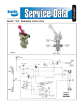
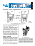
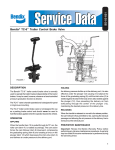
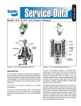
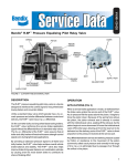
SD-03-950
®
Bendix® LQ-2™ Limiting & Quick Release Valve and TW-1™ Control Valve
SUPPLY PORT
(FROM BRAKE VALVE)
CUT-OUT VALVE
PORT
(FROM
TWO-WAY
VALVE)
DELIVERY PORT (TO
LIMITING AND QUICK
RELEASE VALVE)
DELIVERY PORT
(TO BRAKE CHAMBER)
EXHAUST
PORT
INLET PORT
(FROM BRAKE
VALVE)
LQ-2™ LIMITING & QUICK
RELEASE VALVE
TW-1™ CONTROL VALVE
FIGURE 1
LEVER
PISTON
INLET
VALVE
DIAL
O-RINGS(2)
STEM
PLUNGER RETURN
SPRING
GASKET
EXHAUST
PORT
PLUNGER
SPRING
GUIDE
EXHAUST
VALVE
COVER
INLET VALVE
SPRING
INLET & EXHAUST
VALVE
SEAL RING
FIGURE 2
DESCRIPTION
LQ-2™ LIMITING & QUICK RELEASE VALVE
The Bendix® LQ-2™ limiting and quick release valve is a dual
function valve; the valve serves to limit brake applications
and is generally used on the front or steering axle of a vehicle.
The LQ-2™ valve is controlled by a TW-1™ control valve, (see
Figure 2) which is mounted in the vehicle cab within reach of
the driver. Placing the control valve in the “Slippery Road”
position will reduce front axle service application pressure
by 50%. With the control valve in the “Dry Road” position,
there is no reduction of service application pressure. In
addition, the LQ-2™ valve serves a quick release function,
releasing air directly from the front axle chambers.
1
OPERATION
Reference Figure 2, the LQ-2™ limiting and quick release
valve and the TW-1™ control valve are connected to a service
application line: one connection is to the supply (top) port of
the limiting and quick release valve; the other is to the inlet
port of the two-way control valve. The delivery line from the
two-way control valve is connected to the cut-out valve (side)
port of the limiting and quick release valve.
DRY ROAD POSITION
With the handle of the TW-1™ control valve in the “Dry Road”
position, the valve is in the “on” position and air is permitted
to pass through the valve.
When a foot brake valve application is made, air flows through
the TW-1™ control valve and enters the side port of the limiting
and quick release valve. At the same time, air also enters
the top inlet port; thus pressure acts upon the top and side
areas of the piston, moving the piston down, seating the
exhaust valve, closing the exhaust port. At the same time
the inlet valve opens and air is delivered out the delivery
ports, to the chambers.
When the air pressure beneath the piston (and in the
delivery lines) equals the air pressure being delivered by
the foot valve, the piston raises slightly and closes the inlet
valve. When the foot valve application is released, the air
on the top and side areas of the piston is exhausted back
through the foot valve; air pressure beneath the piston raises
it, and the exhaust valve opens allowing the air in the delivery
lines to exhaust out the exhaust port.
SLIPPERY ROAD POSITION
With the handle of the TW-1™ control valve in the “Slippery
Road” position, the valve is in the “off” position; the inlet
valve is seated and the exhaust is open. In this position air
is not permitted to pass through the valve.
When a foot brake application is made, air enters only the
top inlet port. (Air does not enter the side inlet port because
the TW-1™ control valve is “off”.) Air pressure is effective
only on the upper inner area of the piston; the piston moves
down and the exhaust valve seats and the inlet valve opens.
Air pressure in the delivery line acts on the lower area of the
piston, which is about twice the size of the upper inner area
of the piston. Thus, when the pressure acting upon the lower
area is about half of the brake valve delivered pressure, the
piston lifts and closes the inlet valve. In this position, the air
pressure in the brake chambers is approximately 50% of
brake valve application pressure.
2
WARNING! PLEASE READ AND FOLLOW
THESE INSTRUCTIONS TO AVOID
PERSONAL INJURY OR DEATH:
When working on or around a vehicle, the following
general precautions should be observed at all times.
1. Park the vehicle on a level surface, apply the
parking brakes, and always block the wheels.
Always wear safety glasses.
2. Stop the engine and remove ignition key when
working under or around the vehicle. When
working in the engine compartment, the engine
should be shut off and the ignition key should be
removed. Where circumstances require that the
engine be in operation, EXTREME CAUTION should
be used to prevent personal injury resulting from
contact with moving, rotating, leaking, heated or
electrically charged components.
3. Do not attempt to install, remove, disassemble or
assemble a component until you have read and
thoroughly understand the recommended
procedures. Use only the proper tools and observe
all precautions pertaining to use of those tools.
4. If the work is being performed on the vehicle’s air
brake system, or any auxiliary pressurized air
systems, make certain to drain the air pressure from
all reservoirs before beginning ANY work on the
vehicle. If the vehicle is equipped with an AD-IS™
air dryer system or a dryer reservoir module, be
sure to drain the purge reservoir.
5. Following
the
vehicle
manufacturer’s
recommended procedures, deactivate the electrical
system in a manner that safely removes all
electrical power from the vehicle.
6. Never exceed manufacturer’s recommended
pressures.
7. Never connect or disconnect a hose or line
containing pressure; it may whip. Never remove a
component or plug unless you are certain all
system pressure has been depleted.
8. Use only genuine Bendix ® replacement parts,
components and kits. Replacement hardware,
tubing, hose, fittings, etc. must be of equivalent
size, type and strength as original equipment and
be designed specifically for such applications and
systems.
9. Components with stripped threads or damaged
parts should be replaced rather than repaired. Do
not attempt repairs requiring machining or welding
unless specifically stated and approved by the
vehicle and component manufacturer.
10. Prior to returning the vehicle to service, make
certain all components and systems are restored
to their proper operating condition.
PREVENTIVE MAINTENANCE
LIMITING & QUICK RELEASE VALVE
Important: Review the Bendix Warranty Policy before
performing any intrusive maintenance procedures. A warranty
may be voided if intrusive maintenance is performed during
the warranty period.
Identify all lines to facilitate installation; disconnect lines
and remove valve.
No two vehicles operate under identical conditions, as a
result, maintenance intervals may vary. Experience is a
valuable guide in determining the best maintenance interval
for air brake system components. At a minimum, the limiting,
quick release, and TW-1™ valves should be inspected every
12 months or 3600 operating hours, whichever comes first,
for proper operation. Should the limiting, quick release, and
TW-1™ valves not meet the elements of the operational tests
noted in this document, further investigation and service of
the valve may be required.
2. Disconnect lines.
OPERATING AND LEAKAGE TESTS
2. Install valve with exhaust port, pointing down. Use two
mounting bolts and tighten securely.
OPERATING TEST
For this check, two accurate test gauges will be needed.
Install one gauge in a brake chamber delivery line, and the
other in the foot valve delivery line.
1. Place the control valve in the “Dry Road” position and
make a foot valve application. Readings on both gauges
should be the same.
Release the application and note that air is exhausted
promptly from the exhaust port of the limiting and quick
release valve.
2. Place the control valve in the “Slippery Road” position
and apply the foot valve. The pressure reading on the
gauge in the brake chamber line should be 50% of the
reading of the gauge in the foot valve delivery line.
LEAKAGE TEST
1. Place the control valve in the “Dry Road” position. Make
and hold a foot valve application. Coat the exhaust of
the limiting and quick release valve with soap suds;
leakage should not exceed a 1" bubble in 3 seconds.
2. Place the control valve in the “Slippery Road” position.
Make and hold a foot valve application. Coat the exhaust
of the TW-1™ control valve; leakage should not exceed a
1" bubble in 3 seconds.
If the valve does not function as described above, or if
leakage is excessive, it is recommended that the valve be
replaced with a new or remanufactured unit, or repaired
with genuine Bendix parts.
TW-1™ CONTROL VALVE
1. Identify lines to facilitate installation.
3. Remove two screws on valve dial plate.
4. Remove dial plate
5. Remove valve.
INSTALLING
LIMITING AND QUICK RELEASE VALVE
1. Locate valve near front axle in close proximity to the
chambers it serves.
3. Connect brake chamber lines to delivery ports.
4. Connect brake valve delivery line to top inlet port and
line from control valve to side inlet port.
TW-1™ CONTROL VALVE
1. Place valve handle through mounting hole.
2. Install dial plate; tighten screws.
3. Connect air lines:
(a) from brake valve to inlet port.
(b) to limiting and quick release valve from delivery port.
DISASSEMBLY
LIMITING AND QUICK RELEASE VALVE
1. Remove four (4) cap screws and lockwashers; separate
cover, sealing ring and body.
2. Push piston from body.
3. Remove piston o-rings.
4. Remove exhaust valve, valve guide and spring.
5. Pull the valve stem through the piston; remove inlet valve
from stem.
TW-1™ CONTROL VALVE
1. Remove inlet valve cap nut, spring and inlet/exhaust valve.
Remove cap nut seal ring.
2. Drive out lever pin and remove lever.
3. Remove plunger and plunger spring.
4. Remove plunger o-ring.
REMOVING AND INSTALLING
Block and hold vehicle by means other than air brakes.
3
CLEANING AND INSPECTION
Wash all metal parts in mineral spirits; wipe rubber parts dry.
Inspect all parts for signs of wear and/or deterioration.
Inspect springs for cracks, distortion or corrosion and inspect
all metal valve seats for nicks or scratches.
It is recommended that all rubber parts be replaced, and
that any part showing signs of wear or deterioration be
replaced.
ASSEMBLY
LIMITING AND QUICK RELEASE VALVE
1. Install inlet valve on stem (note: lubricating the valve with
silicone will aid installation).
2. Insert stem through pistons, position spring and valve
guide over stem and press exhaust valve boot on stem.
3. Lubricate body and cover bores, o-rings and o-ring grooves
with Dow Corning 55M pneumatic grease (Bendix piece
no. 291126).
5. Install piston assembly in body. Be careful not to damage
o-rings.
6. Install sealing ring in body; install cover to body.
7. Install four (4) cap screws/lockwashers; torque to
approximately 100 inch pounds.
TW-1™ CONTROL VALVE
Prior to assembly, lubricate body bores, plunger and o-rings
with Dow Corning 55-M pneumatic grease (Bendix piece
no. 291126).
1. Install inlet/exhaust valve and spring in body.
2. Install cap nut and sealing ring.
3. Install plunger o-ring, plunger spring and plunger into
body.
4. Position lever in body slot, line up lever hole and install
pin.
5. Test valves as outlined in “Operating and Leakage” test
section.
4. Install o-rings on piston assembly.
BW1439 © 2004 Bendix Commercial Vehicle Systems LLC All rights reserved. 3/2004 Printed in U.S.A.
4