1
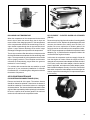
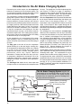
TO RESERVOIR
INLET VALVE
UNLOADER
PLUNGER
DISCHARGE
VALVE
INTAKE
STRAINER
PISTON
FIGURE 4
OPERATION
TO GOVERNOR
GENERAL
STROKE
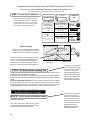
All compressors run continuously while the engine is
running, but actual compression of air is controlled by a
governor which stops or starts the compression of air by
loading or unloading the compressor in conjunction with its
unloading mechanism. This is done when the air pressure
in the system reaches the desired maximum or minimum
pressures.
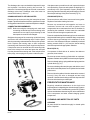
TO RESERVOIR
INLET VALVE
UNLOADER
PLUNGER
DISCHARGE
VALVE
PISTON
COMPRESSION
FIGURE 6
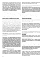
NON-COMPRESSION (UNLOADED)
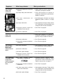
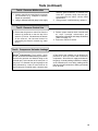
When the air pressure in the reservoir reaches the high
pressure setting of the governor, the governor opens,
allowing air to pass from the reservoir through the governor
and into the cavity beneath the unloader pistons. This lifts
the unloader pistons and plungers. The plungers move up
and hold the inlet valves off their seats (Fig. 7).
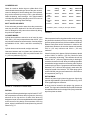
INTAKE
STRAINER
TO GOVERNOR
STROKE
INTAKE
FIGURE 5
TO RESERVOIR
INLET VALVE
UNLOADER
PLUNGER
DISCHARGE
VALVE
PISTON
INTAKE
STRAINER
INTAKE AND COMPRESSION (LOADED)
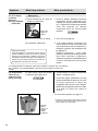
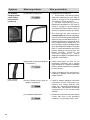
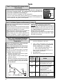
During the down stroke of the piston, a slight vacuum created
above the piston causes the inlet valve to move off its seat.
Atmospheric air is drawn in through the compressor intake,
by the open inlet valve, and on top of the piston (Fig. 5). As
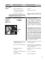
the piston starts its upward stroke, the air that was drawn in
on the down stroke is being compressed. Now, air pressure
on top of the inlet valve plus the force of its spring, returns
the inlet valve to its seat. The piston continues the upward
stroke and compresses the air sufficiently to overcome the
discharge valve spring and unseat the discharge valve. The
compressed air then flows past the open discharge valve,
into the discharge line and on to the reservoirs (Fig. 6).
As the piston reaches the top of its stroke and starts down,
the discharge valve spring returns the discharge valve to its
seat. This prevents the compressed air in the discharge
line from returning to the cylinder bore as the intake and
compression cycle is repeated.
TO GOVERNOR
STROKE
UNLOADING
FIGURE 7
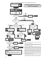
With the inlet valves held off their seats by the unloader
pistons and plungers, air is merely pumped back and forth
between the two cylinders. When air is used from the
reservoir and the pressure drops to low pressure setting of
the governor, the governor closes and in doing so exhausts
the air from beneath the unloader pistons. The unloader
saddle spring forces the saddle, pistons and plungers down
and the inlet valves return to their seats. Compression is
then resumed.
3