1
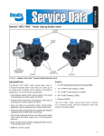
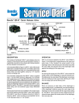
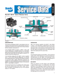
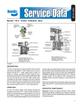
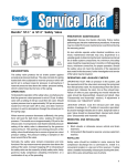
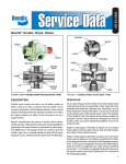
SD-03-3672
®
Bendix® TW-N™ Two Way Control Valve
LEVER
LEVER PIN
MOUNTING
HOLE (4)
BODY
PLUNGER
O-RING (LARGE)
EXHAUST
.26” O.D.
(6.6 MM)
SPRING
DELIVERY
PORT
1/8” P.T.
O-RING (SMALL)
DELIVERY
PORT
SUPPLY
PORT
1/8” P.T.
SUPPLY
PORT
FIGURE 1
DESCRIPTION
The TW-N™ valve is a manually operated two position control
valve. It is normally dash or panel mounted and incorporates
a manually operated control lever. The TW-N™ valve was
designed for use as a control for non-modulating air system
devices.
With the exception of the plunger return spring, lever pin
and lever reinforcement the TW-N™ valve is constructed of
nonmetallic material.
The single supply port and delivery port are both tapped with
a 1/8" female pipe thread to accommodate air connections.
A single .26" (6.6 mm) O.D., unthreaded exhaust nipple is
located on the side and midway down the valve body. Each
port is identified with embossed letters; SUP for supply,
DEL for delivery and EXH for the exhaust.
The TW-N™ valve is generally mounted using two of the four
mounting holes that are provided. All four mounting holes
are tapped with a 10-24 thread.
The TW-N™ valve is interchangeable with the TW-1™ two-way
control valve with respect to vehicle fit and function. Dial
plates and attaching screws can be used interchangeably
on either the TW-N™ and TW-1™ valves, however other detail
components are not interchangeable.
OPERATION
With the TW-N™ valve in the exhaust position, air at the
supply port is prevented from flowing to the delivery port by
the lower o-ring on the plunger. (Figure 2) When the lever is
moved to the delivery position, (Figure 3) the return spring
and air pressure moves the plunger allowing the lower plunger
o-ring to slide past the delivery port passage. With the plunger
in this position (Figure 3), air flows from the supply port and
out the delivery port.
1
EXHAUST
EXHAUST
DELIVERY
PORT
DELIVERY
PORT
SUPPLY PORT
EXHAUST POSITION
FIGURE 2
Moving the lever to the exhaust position, forces the plunger
toward the supply port, causing the lower plunger o-ring to
slide past the delivery port passage sealing the supply from
the delivery. Air at the delivery flows through the valve body,
around the plunger and out the exhaust.
SUPPLY PORT
DELIVERY POSITION
FIGURE 3
2. With the TW-N™ valve in the exhaust position apply a
soap solution to the exhaust. Leakage should not exceed
a 1" (25.4 mm) bubble in 5 seconds or less.
PREVENTIVE MAINTENANCE
3. With the TW-N™ valve in the air delivery position apply a
soap solution to the exhaust and around the plunger.
Leakage should not exceed a 1" (25.4 mm) bubble in 5
seconds or less.
Important: Review the Bendix Warranty Policy before
performing any intrusive maintenance procedures. A warranty
may be voided if intrusive maintenance is performed during
the warranty period.
If the TW-N™ valve does not function as described or leaks
excessively, it should be replaced or repaired using a
genuine Bendix maintenance kit available at authorized
Bendix parts outlets.
No two vehicles operate under identical conditions, as a
result, maintenance intervals may vary. Experience is a
valuable guide in determining the best maintenance interval
for air brake system components. At a minimum, the TW-N™
valve should be inspected every 6 months or 1500 operating
hours, whichever comes first, for proper operation. Should
the TW-N™ valve not meet the elements of the operational
tests noted in this document, further investigation and service
of the valve may be required.
OPERATION AND LEAKAGE TESTS
1. With vehicle air pressure at governor cut-out and the
engine turned off, place the TW-N™ valve control lever in
the air delivery position. Note that the device being
controlled promptly responds. Place the control lever in
the air exhaust position and note that air is promptly
and completely exhausted from the TW-N™ valve.
2
WARNING! PLEASE READ AND FOLLOW
THESE INSTRUCTIONS TO AVOID
PERSONAL INJURY OR DEATH:
When working on or around a vehicle, the following
general precautions should be observed at all times.
1. Park the vehicle on a level surface, apply the
parking brakes, and always block the wheels.
Always wear safety glasses.
2. Stop the engine and remove ignition key when
working under or around the vehicle. When
working in the engine compartment, the engine
should be shut off and the ignition key should be
removed. Where circumstances require that the
engine be in operation, EXTREME CAUTION should
be used to prevent personal injury resulting from
contact with moving, rotating, leaking, heated or
electrically charged components.
3. Do not attempt to install, remove, disassemble or
assemble a component until you have read and
thoroughly understand the recommended
procedures. Use only the proper tools and observe
all precautions pertaining to use of those tools.
4. If the work is being performed on the vehicle’s air
brake system, or any auxiliary pressurized air
systems, make certain to drain the air pressure from
all reservoirs before beginning ANY work on the
vehicle. If the vehicle is equipped with an AD-IS™
air dryer system or a dryer reservoir module, be
sure to drain the purge reservoir.
5. Following
the
vehicle
manufacturer’s
recommended procedures, deactivate the electrical
system in a manner that safely removes all
electrical power from the vehicle.
6. Never exceed manufacturer’s recommended
pressures.
7. Never connect or disconnect a hose or line
containing pressure; it may whip. Never remove a
component or plug unless you are certain all
system pressure has been depleted.
8. Use only genuine Bendix ® replacement parts,
components and kits. Replacement hardware,
tubing, hose, fittings, etc. must be of equivalent
size, type and strength as original equipment and
be designed specifically for such applications and
systems.
9. Components with stripped threads or damaged
parts should be replaced rather than repaired. Do
not attempt repairs requiring machining or welding
unless specifically stated and approved by the
vehicle and component manufacturer.
10. Prior to returning the vehicle to service, make
certain all components and systems are restored
to their proper operating condition.
2. Using a drift punch, drive the lever pin out and remove
the lever.
3. Remove the plunger and plunger return spring.
4. Remove both the large and small diameter o-rings from
the plunger.
CLEANING AND INSPECTION
1. Clean the valve body, plunger return spring and plunger
in a mild solvent such as mineral spirits and dry
thoroughly.
2. Inspect the valve body bore and piston for scratches,
nicks, cracks and distortion. If noted, the entire TW-N™
valve must be replaced.
3. Inspect the return spring for distortion and corrosion. If
noted, the entire TW-N™ valve must be replaced.
ASSEMBLY
Prior to assembly lubricate the valve body bore, plunger and
o-rings with Bendix silicone lubricant Pc. Nos. 291126.
1. Install large and small diameter o-rings on plunger.
2. Install plunger return spring in body and install plunger.
3. Note the lever position marked during disassembly. Care
should be exercised as lever can be installed in either
position. (Lever position is dictated by function marked
on dial or dash.) Place lever in body and gently depress
the lever and plunger until the lever pin holes in the
body and the lever are aligned.
4. Install the lever pin and press into position. It may be
necessary to hold the lever to guide the pin into the
body hole opposite the press. The lever pin should be
flush with the body on one side.
INSTALLING
1. Install the TW-N™ valve on the vehicle.
2. Drain all reservoirs to 0 p.s.i. (0 kPa) air pressure.
2. Connect the air lines to the TW-N™ valve according to
the markings made during “Removal”. IMPORTANT:
Fittings installed in the supply and delivery ports of the
TW-N™ valve should not be torqued to greater than 8 ft.
lbs. (10.85 N.M).
3. Identify, mark and remove the air lines from the TW-N™
valve.
3. Before placing the vehicle in service, perform the
“Operation and Leakage Tests”.
REMOVING
1. Secure the vehicle on a level surface by means other
than the brakes.
4. Remove the TW-N™ valve from the vehicle.
DISASSEMBLY
1. Before disassembly, move the TW-N™ valve lever to the
air delivery position and note or mark the position of the
lever relative to the valve body. NOTE: The TW-N™ valve
is in the air delivery position when the plunger is closest
to the mounting surface of the body. Confirm that the
TW-N™ valve is in the air delivery position by applying air
to the supply port and noting that it exits the delivery
port.
BW1444 © 2004 Bendix Commercial Vehicle Systems LLC. All rights reserved. 3/2004 Printed in U.S.A.
3