1
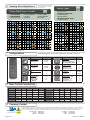
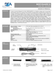
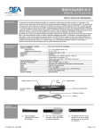
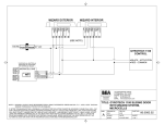
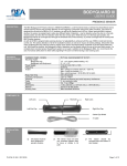
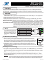
BODYGUARD III
QUICK SETUP GUIDE
PRESENCE SENSOR FOR PEDESTRIAN DOORS
1 Description
The Bodyguard III Quick Setup Guide is for the installation and setup of the Bodyguard III. This document is provided for experienced installers,
service personnel & AAADM Certified Inspectors that are familiar with the Bodyguard III. For those who are not completely familiar with the
installation and setup of the Bodyguard III, BEA recommends following the detailed installation and setup instructions found in the Bodyguard III
User’s Guide (75.5134). Bodyguard performance shall be adjusted and in compliance with all applicable current safety standards (ANSI A156.10).
2 Installation
1. The Bodyguard shall be mounted near flush with the bottom of the automatic door header on the swing side. This is absolutely necessary to allow
the Bodyguard detection pattern to reach back through the threshold area when the door is in the open position. If any portion of the door face or
related hardware on the swing side project beyond the Bodyguard face, a Bodymount must be installed in conjunction with the Bodyguard.
2. The Bodyguard should be mounted at a height range of 6’ 6” to 8’ (Max. of 9’).
3. The Bodyguard should be center mounted up above on the header and flush with the bottom of the automatic door header. This is absolutely
necessary to allow the detection pattern to reach back through the threshold area with the Bodyguard is in the open door position.
SINGLE DOOR APPLICATIONS - The Bodyguard should be mounted overhead at the center of the door opening. However, if this is not possible, the
unit may be installed off-center. In such cases, pattern location will have to be altered for proper placement of the
field of detection. Try to avoid mounting locations that may pose potential problems such as directly over a door arm.
DOUBLE-EGRESS APPLICATIONS - One Bodyguard shall be mounted overhead on the header over each swing-path. There should be at least 40”
of separation between the 2 Bodyguards when measured between the centerline of each sensor. Most double
egress applications are knowing act. Ensure compliance with current ANSI 156.10-2005 Section 9.2. Most
double egress installations will require IR frequency and/or open door pattern depth adjustments. Change IR
frequency of one Bodyguard to 3 and the other to 4 (See Tech Bulletin #32 or Bodyguard User Guide 75.5134
for more explicit information regarding double egress applications with respect to location and setting up the
Bodyguard.
3 Wiring
Use the cable that is provided for use with the
10-pin connector as shown or wire the 7-pin
terminal block. If wiring the Bodyguard to a
BEA module (i.e. LO LINX or a version of the
LO-21), refer to the wiring diagrams for the
respective module. For ease of installation,
wire the terminal before attaching it to the
Bodyguard.
POS
1
2
3
4
5
6
7
WIRE COLOR
(10-Pin Cable)
12 to 24 VAC/VDC +/- 10%
Red
12 to 24 VAC/VDC +/- 10%
Black
COM
White
NO
Green
NC
Data Brown
Data +
Blue
CONNECTION (7-Pin)
RED
BLACK
WHITE
GREEEN
BROWN
BLUE
1 PWR
2 PWR
3 COM
4 NO
5 NC
6 IN 7 IN +
10 PIN
PCB
NOTE: Never short the data wires
when power is applied as this
will destroy the lockout.
4 Mechanical Adjustment
5° Default Angle
1. Aside from placement on the header, the only mechanical adjustment that may be made to the sensor is the angle
adjustment. The Bodyguard is factory pre-set to the +5° position, but may be reduced to a 0° position or increased to
a 10° position. The greater the angle, the farther from the door the pattern will be. The 0° angle should only be used
when the Bodyguard is mounted to a Bodymount block or to a soffit above the door that extends out from the face of the
swing side of the door (in this case, the 0° setting would improve the location of the detection field across the threshold
area of the doorway). It is recommended that for most applications, the unit be powered and walk tested at the pre-set
5° angle. After walk testing, if the detection field needs to be changed, then proceed with changes as explained next.
2. To change the angle setting the end caps, lenses, center eye shield and terminal block if it has been wired must be
removed. Once removed, release the white clips and rotate outward to remove the PCB. Once the PCB is completely
removed from the housing, the angle position may be changed. There are two clips per Bodyguard and the angle must
match for each clip on the PCB.
ANGLE ADJUSTMENT
CLIP (WHITE)
5 Setup
1. Upon completion of mechanical and electrical installation, apply 12 to 24 VAC/VDC +/- 10% to the Bodyguard with the door in the closed position.
The Bodyguard will flash a green LED at a rate of 2 Hz, then it will expire upon a successful set-up in the door closed position.
NOTE: If applying the Bodyguard to a door control that requires a learn cycle upon powering, it is recommended to allow the doors to complete a
learn cycle before applying power to the Bodyguard.
2. Activate the door to the full open position. When using BEA’s lockout relay, the Bodyguard will once again flash the green LED and will
execute a door-open set-up. Upon completion of the set-up for the door-open position, the doors will begin closing. Normal operation should
resume thereafter. Proceed with fine-tuning to insure compliance with all current applicable safety standards (i.e. ANSI A 156.10). If set-up is
unsuccessful, refer to the Troubleshooting Guide at the end of the Bodyguard User’s Guide (75.5134) and also to the guide located at the end of
the respective lockout User’s Guide.
HELPFUL HINT: After set-up and to confirm the correct motor polarity to the lockout, the correct data and data polarity and to ensure the lockout is
communicating properly to the Bodyguard. Activate the door open and perform a door open set-up with the remote by pressing
Unlock, Magic Wand, #2. If the Bodyguard flashes green continue with final tune in. If not, refer to Bodyguard User Guide
(75.5134). The most likely cause is the motor lead polarity is reversed at the lockout or data polarity is reversed at Bodyguard.
75.5362.01 20090210
Page 1 of 2
Pattern Width, Depth & Sensitivity all
have independent door closed and
door open values.
6 Sensing Zone Adjustment
Pattern Depth
Pattern Width (Open / Closed)
1: Wide (CLOSED DOOR)
2: Middle (OPEN DOOR)
3: Asymmetric Left Narrow
4: Asymmetric Right Narrow
5: Narrow Left
6: Narrow Right
1: Deep (Threshold ON)
2: Medium (Threshold ON - OPEN)
3: Limited (Threshold ON)
4: Deep (Threshold OFF)
5: Medium (Threshold OFF - CLOSED)
6: Limited (Threshold OFF)
7: Asymmetric Left Wide
8: Asymmetric Right Wide
9: Center Narrow
1ST ROW OF IR
THRESHOLD
1ST ROW OF IR
2ND ROW OF IR
THRESHOLD
3RD ROW OF IR
4TH ROW OF IR
1
2
3
4
5
7
8
2ND ROW OF IR
1
2
6
3
4
9
5
6
3RD ROW OF IR
4TH ROW OF IR
NOTE: When pattern width or depth is changed, a setup of the new pattern size will automatically be triggered
once a value key has been pressed.
7 Configurations
ENSURE COMPLIANCE WITH ALL APPLICABLE CURRENT SAFETY STANDARDS (I.E. ANSI A156.10).
BUTTON
VALUE
PARAMETER
BUTTON
VALUE
PARAMETER
SENSITIVITY
Door Closed = 6
Door Open = 7
0 (min)
9 (max)
INTERFACE
New Style
Old Style (LO21, B, K,
P, S, U, LO-LINX, MC15)
AUTO LEARN
0 = 30 sec
9 = Infinite
0 (min)
9 (max)
SETUP / WAND
Door Closed = 1
Door Open = 2
Restore to Default
OUTPUT CONFIG.
NO
NC
IMMUNITY
Low (Normal)
Medium (Rain)
High (Snow) *
* - BGIII-C
1
2
9
HOLD TIME
0 = 0.5 sec
9 = 9 sec
1
2
0 (min)
9 (max)
FREQUENCY
Normal Mode; Low
Normal Mode; High
Quiet Mode; Low
Quiet Mode; High
1
2
3*
1
2
1
2
3
4
8 Door Control Connections
SWING
SWING
ACT
COM
SAF
STILL
HUNTER
ACT
RTN
SAF 1
SAF 2
RTN
KM K
Green
White
Red
Yellow
White
Grey
STANLEY L
Orange
Yellow
Red
Blue
Yellow
ACT
COM
SAF
STALL
STALL COM
Besam 300
13
12
11
15, 17
16, 18
Besam M/P
3
4
9
5
13
Yellow
Grey
Blue
Purple
DOM
GT 300/400
GT MAG
HORTON 4190
STALL COM
Black
Red
White
White
Red
STANLEY M/P
2
1, 8
7
7
1, 8
6 Black
5 Red
4 White
3 Violet
5 Red
STANLEY 521
TB4-5
TB4-4
TB4-8
TB4-10
TB4-9
2
3, 6, 8
4
10
3, 6, 8
TORMAX TDA
2
1, 3, 6, 8
8&9
7
1, 3, 6, 8
9 Company Contact
Do not leave problems unresolved. If a satisfactory solution cannot be achieved after troubleshooting a problem, please call BEA, Inc. If you must wait for the
following workday to call BEA., leave the door inoperable until satisfactory repairs can be made. Never sacrifice the safe operation of the automatic door or
gate for an incomplete solution. The following numbers can be called 24 hours a day, 7 days a week. For more information, visit www.beasensors.com.
US and Canada:
Canada:
Northeast:
1-866-249-7937
1-866-836-1863
1-866-836-1863
Southeast:
Midwest:
West:
Page 2 of 2
1-800-407-4545
1-888-308-8843
1-888-419-2564
75.5362.01 20090210