1
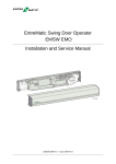
Besam Low Energy Swing Door Operator
SW100
Installation and Service Manual
1003680-US-4.0 – Issue 2007-10-11
ASSA ABLOY, the global leader in door opening solutions
© All rights in and to this material are the sole property of ASSA ABLOY Entrance Systems AB. Copying, scanning, alterations or modifications are expressly forbidden without the prior written consent of the applicable company within ASSA
ABLOY Entrance Systems AB. Rights reserved for changes without prior notice.
2
Issue 2007-10-11
1003680-US-4.0
Table of content
1
Revision . . . . . . . . . . . . . . . . . . . . . . . . . . . . . . . . . . . . . . . . . . . . . . . . . . . . . . . . . . . . . . . .4
2
Important information . . . . . . . . . . . . . . . . . . . . . . . . . . . . . . . . . . . . . . . . . . . . . . . . . . . . . .5
3
Introduction . . . . . . . . . . . . . . . . . . . . . . . . . . . . . . . . . . . . . . . . . . . . . . . . . . . . . . . . . . . . .6
4
Technical specification . . . . . . . . . . . . . . . . . . . . . . . . . . . . . . . . . . . . . . . . . . . . . . . . . . . . .7
5
How the SW100 works. . . . . . . . . . . . . . . . . . . . . . . . . . . . . . . . . . . . . . . . . . . . . . . . . . . . .8
6
Models . . . . . . . . . . . . . . . . . . . . . . . . . . . . . . . . . . . . . . . . . . . . . . . . . . . . . . . . . . . . . . . .12
7
Part identification . . . . . . . . . . . . . . . . . . . . . . . . . . . . . . . . . . . . . . . . . . . . . . . . . . . . . . . .13
8
Options. . . . . . . . . . . . . . . . . . . . . . . . . . . . . . . . . . . . . . . . . . . . . . . . . . . . . . . . . . . . . . . .14
9
Pre-installation . . . . . . . . . . . . . . . . . . . . . . . . . . . . . . . . . . . . . . . . . . . . . . . . . . . . . . . . . .20
10
Mechanical installation . . . . . . . . . . . . . . . . . . . . . . . . . . . . . . . . . . . . . . . . . . . . . . . . . . . .23
11
Electrical connection . . . . . . . . . . . . . . . . . . . . . . . . . . . . . . . . . . . . . . . . . . . . . . . . . . . . .31
12
Start-up . . . . . . . . . . . . . . . . . . . . . . . . . . . . . . . . . . . . . . . . . . . . . . . . . . . . . . . . . . . . . . .36
13
Changing group of parameters . . . . . . . . . . . . . . . . . . . . . . . . . . . . . . . . . . . . . . . . . . . . .42
14
Cover . . . . . . . . . . . . . . . . . . . . . . . . . . . . . . . . . . . . . . . . . . . . . . . . . . . . . . . . . . . . . . . . .43
15
ANSI / BHMA A156.19 . . . . . . . . . . . . . . . . . . . . . . . . . . . . . . . . . . . . . . . . . . . . . . . . . . . .44
16
Troubleshooting . . . . . . . . . . . . . . . . . . . . . . . . . . . . . . . . . . . . . . . . . . . . . . . . . . . . . . . . .47
17
Planned maintenance checklist . . . . . . . . . . . . . . . . . . . . . . . . . . . . . . . . . . . . . . . . . . . . .49
1003680-US-4.0
Issue 2007-10-11
3
Revision
1
Revision
The following pages have been revised:
4
Page
Revision
5
2.3
7
Cover depth changed from 5 3/16” to 5 1/8”
Glazing materials added
Issue 2007-10-11
1003680-US-4.0
Important information
2
2.1
Important information
Important notice
To avoid bodily injury, material damage and malfunction of the product, the instructions contained in this manual must be strictly observed during installation, adjustment, repairs and service, etc. Only Besam-trained technicians should be allowed to
carry out these operations.
2.2
Radio and television reception
This equipment generates and uses radio frequency energy and if not installed and
used properly, that is, in strict accordance with the manufacturer's instructions, it may
cause interference to radio and television reception. It has been designed to comply
with the emission limits in accordance with EN 61000-6-3 and EN 61000-6-2 (US
market FCC 47 CFR Part 15B), which are designed to provide reasonable protection
against such interference in a residential installation. However, there is no guarantee
that interference will not occur in a particular installation. If this equipment does
cause interference to radio or television reception, which can be determined by turning the equipment off and on, the user is encouraged to try to correct the interference
by one or more of the following measures:
• Re-orient the receiving antenna.
• Relocate the receiver with respect to the equipment.
• Move the receiver away from the equipment.
• Plug the receiver into a different outlet so that equipment and receiver are on different branch circuits.
• Check that protective earth (PE) is connected.
If necessary, the user should consult the dealer or an experienced radio/television
technician for additional suggestions.
2.3
Glazing materials
The glazing material for swing doors shall comply with ANSI Z97.1
1003680-US-4.0
Issue 2007-10-11
5
Introduction
3
Introduction
This manual contains the necessary details and instructions for the installation, maintenance and service of the low energy swing door operator SW100, a universal electro-mechanical operator suitable for all low energy applications of swing doors.
The SW100 can be mounted on either side of the door header for pull or push action,
and is suitable for single or double doors fitted with butt hinges, offset or center
pivots.
The SW100 ensures all-around safety. The operator can be combined with a full
range of sensor products providing swing door safety, but meets also the requirements for a low energy operator without any sensors.
6
Issue 2007-10-11
1003680-US-4.0
Technical specification
4
Technical specification
Power supply:
Power consumption:
Auxiliary voltage:
Internal control fuse:
Door width:
Electro-mechanical locking
device
Door weight:
Door opening angle:
Opening time (0° - 80°):
Closing time (90° - 10°):
Hold open time:
Ambient temperature:
Relative humidity
(non-condensing)
120 V AC +10/-15%, 50/60 Hz
max. 75 W
24 V DC, max. 400 mA
2 x T 6.3 AH 250 V
36-48” (914-1219 mm)
Selectable: 12V DC, max. 500 mA / 24 V DC,
max. 250 mA
100-200 lb. (45-90 kg)
Push arm:80° - 110°, with reveal 0 - 11 13/16”
(0 - 300 mm)
Pull arm: 80° - 110°, with reveal 0 - 5 1/8”
(0 - 130 mm)
variable between 3 - 6 seconds
variable between 3 - 6 seconds
1.5-30 seconds
-4 °F to +113 °F (-20 °C to +45 °C)
Max. 85%
This product is to be installed internally or externally with suitable weather protection.
Class of protection IP 20.
Complies with: IEC 335-1, ANSI/BHMA A156.19 and UL 325.
1 1/2’’
1 3/8’’
4 5/16’’
1 1/2’’
5/8’’
5 1/8’’
2 9/16’’
ILL-01658
1003680-US-4.0
Issue 2007-10-11
7
How the SW100 works
5
How the SW100 works
The low energy swing door operator SW100 uses a DC motor and a gear-reduction
system to drive an arm system, which opens the door. Closing power is provided by a
motor and a clock spring. An electronic control unit uses a motor encoder and a
microprocessor to control the door’s movement.
5.1
Opening
When an opening signal is received by the control unit, the door is opened at the
operator-adjusted opening speed. Before the door is fully open at back check, it slows
automatically to low speed. The motor stops when the selected door opening angle
has been reached. The open position is held by the motor.
If the door is obstructed while opening, it will either stall or stop which can be
selected with a DIP-switch (SOS).
• When stalling - the door will continue to try to open during the hold open time.
• When stopping - the door will, even if hold open time has not expired, close after
2 seconds.
5.2
Closing
When the hold open time has elapsed, the operator will close the door automatically,
using spring force and motor. The door will slow to low speed at latch check before it
reaches the fully closed position. The door is kept closed by spring power or
extended closing force by the motor.
8
Issue 2007-10-11
1003680-US-4.0
How the SW100 works
5.3
Functions on the basic control unit CU-ESD (see also page 32)
5.3.1
Power failure
During power failure the operator acts as a door closer with controlled closing speed.
5.3.2
Spring force
The operator is delivered with spring pre-tension factory set to 210°. If necessary, the
spring tension can be electronically adjusted with a potentiometer to required closing
force.
5.3.3
Extended closing force/torque (CLTQ)
If the potentiometer CLTQ is set to 0°, the door will close with normal spring power. If
the potentiometer is turned clockwise, the motor will increase the closing force/torque.
5.3.4
Power assist (POAS)
If the potentiometer POAS is set to 0°, the door gives no power assist. If the potentiometer is turned clockwise, the motor will give/increase power assist when the door
is opened manually.
5.3.5
Push and go (PAG)
DIP-switch to select “Push and Go” On or Off. “Push and Go” is available from any
door position.
5.3.6
Overhead presence detector (OPD), frame mounted
When an OPD sensor is mounted on the frame or operator header just above the
swing side of the door, it will–when activated–either keep the door open or closed.
The sensor is not active during opening and closing. Lock-out signal must be connected for proper function.
• a closed door will not open, if the OPD detects activity in the field
• an open door will not close, if the OPD detects activity in the field
• during opening, the door will continue to open, even if the OPD detects activity in
the field
• during closing, the door will continue to close, even if the OPD detects activity in
the field
• the OPD is not active in program mode OFF, manually opened door or during battery operation (Power Save Mode).
1003680-US-4.0
Issue 2007-10-11
9
How the SW100 works
5.3.7
Mat
Mat safety means that:
• a closed door will not open, if someone steps on the mat
• an open door will not close, if someone steps on the mat
• during opening, the door will continue to open, even if someone steps on the mat
• during closing, the door will continue to close, even if someone steps on the mat
• opening impulses are prevented during closing, if someone steps on the mat
• the mat is not active in program mode OFF, manually opened door or during battery operation (Power Save Mode).
5.4
Functions on the extension unit EXU-SI (see also page 34)
5.4.1
Kill function
• If kill circuit is closed, the control will ignore all signals and close door(s) at normal speed.
• When kill is no longer active, operator will resume normal operation.
• If kill function must have manual reset, jumper must be removed and reset button
connected to terminal No. 8 and Ground.
• The lock will lock when kill is active regardless of program selector setting.
• The function of the lock can be changed during Kill (see page 42).
5.4.2
Function of locks
•
•
•
•
The control has an available output of DC for external locks
DIP-switches to select 12 or 24 V DC, locked with or without power
DIP-switch for lock release and potentiometer for opening delay
DIP-switch for lock kick if door is not fully closed, to overcome binding in the
locking device during closing
• Input to unlock signal from lock. Potentiometer for opening delay is to be set to
max. As soon as unlock signal is received the door will start to open. The output
signal shall be active low.
5.4.3
Program selector
• Input for OPEN, EXIT and OFF (if no program selector, AUTO is default).
5.4.4
Impulses
• Input for Outer impulse, Key impulse and Open/Close impulse.
10
Issue 2007-10-11
1003680-US-4.0
How the SW100 works
5.4.5
Open / close impulse
The impulse will open the door and the door will stay open until a new impulse is
given. If no impulse is given the door will close after 15 minutes. This can be made
infinite by changing group of parameters (see page 42).
Open/close impulse works only in program selection “On”.
5.5
Functions on the extension unit EXU-SA (see also page 35) – optional
5.5.1
Presence impulse approach, door mounted
The presence impulse is active during fully open and closing. The sensor is mounted
to the approach side of the door. Once the door is closed, the sensor is ignored and
will not be active until the next impulse is received.
Note: When installed as a pair of doors, the presence impulse signal will re-open
both doors. The sensor is not active in program mode OFF, manually opened
door or during battery operation (Power Failure Mode).
5.5.2
Presence detection swingpath, door mounted
When a sensor that is mounted on the swing side of a door detects an object, it will
send a command to the control unit to stall the door. If the control unit has received a
short signal from the sensor and there is still hold open time left on the control unit,
the door will continue on its way open if the object has cleared. The inhibit/blanking
potentiometer can be adjusted so that the sensor will avoid detecting a wall or object
near the full open position. Presence detection has a higher priority than presence
impulse.
Note: When installed as a pair of doors the presence detection signal will stop both
doors, except for double egress doors. The behavior for double egress doors
can be changed (see page 42). The sensor is not active in program mode OFF,
manually opened door or during battery operation.
5.5.3
Monitored safety sensors
Both presence impulse and presence detection can be monitored. If a sensor becomes
defective, the operator will not accept any impulses and will then work as a manual
door closer.
5.5.4
Open door indication
A relay output is used to indicate an opening cycle or a specific position of the door.
The indication position is set by adjusting the inhibit/blanking potentiometer.
5.5.5
Error indication
A potential free contact COM/NO/NC for external error indication (see page 48).
1003680-US-4.0
Issue 2007-10-11
11
Models
6
Models
Two main models of the low energy swing door operator SW100 are available:
• Single operator
• Double operator
The operators are non-handed and not dependent on the hinges. The operators suit
both pushing and pulling arm systems.
6.1
Single operator
The product is delivered complete with back plate, control unit, end plates and cover.
Length including end plates, L = 39.5” (1003 mm).
Pushing arm system shown.
L
6.2
Double operator (Consult Product Order form for availability)
The product is delivered complete with back plate, control unit, end plates and cover.
Cover length L is optional.
Two operators can be mounted under the same cover to open one door each.
Pushing and pulling arm system shown (double egress).
L
12
Issue 2007-10-11
1003680-US-4.0
Part identification
7
Part identification
11
1
10
12
14
9
7
2
3
5
4
6
8
13
6
Item No.
P/N
Description
1
1003547
Back plate (shorty)
2
1003498
Transmission unit/operator
3
1003532
Control unit CU-ESD
1003554
EXU-SI (Kit to extend the security functions) – optional
1003557
EXU-SA (Kit to extend the safety functions) – optional
4
1700607
Mains contact
5
1003540
Door stop body
6
1003542
Top end plate
7
1003543
Bottom end plate
8
1003546
Main cover (shorty)
9
1003581
Power On/Off switch
1003582
On/Off/Hold open switch – optional
10
Cable holder (50 pcs)
–
Knockouts for cable inlet
12
–
Belt tension device
13
1003680-US-4.0
1003578
11
1003545
Fill cover (output shaft)
14
1004437
Connection box
–
1003583
Sync cable – optional
Issue 2007-10-11
13
Options
8
8.1
Options
Arm systems
8.1.1
Arm system, PUSH P/N: 1003576
This arm system is delivered with drive arm, telescopic part and door fitting. It is
used if the operator is installed on the wall on the opposite side of the door swing, and
approved for fire door application.
PUSH
8.1.2
PUSH-arm extensions
Reveal = X
Extension
Up to 4-1/8” (0-105 mm)
None (standard arm)
4-1/8” to 8-11/16” (105-220 mm)
13-9/16” (345 mm)
8-11/16” to 11-13/16” (220-300 mm)
9-1/16” (230 mm) + Joint part
13-9/16” (345 mm) extension
P/N: 21-06-17305
9-1/16” (230 mm) extension
P/N: 21-06-17304
Joint part
P/N: 21-06-17319
X
14
Issue 2007-10-11
1003680-US-4.0
Options
8.1.3
Arm system, PULL P/N: 1003577
This arm system is delivered with drive arm, guide shoe and door fitting.
PULL
8.1.4
Reveal spacer, PULL
P/N: 173804BK
60 mm
(2-3/8")
40 mm (1-9/16")
40 (1-9/16")
8.1.5
60 (2-3/8")
Drive shaft extension kits
70 mm
(2-3/4")
50 mm
(2")
20 mm
(3/4")
P/N: 21-03-205
1003680-US-4.0
P/N: 21-03-206
Issue 2007-10-11
P/N: 21-03-207
15
Options
8.2
Push plates
For disable use, mount push plate 31” above floor level.
8.2.1
Push plates
PRESS
TO OPEN
P/N: 75-02-101
P/N: 75-02-102
PRESS
TO OPEN
P/N: 75-02-107
8.2.2
P/N: 75-02-108
Remote transmitter push plates
PUSH
P/N: 75-02-273
PUSH
TO
OPEN
PUSH
TO OPEN
8.2.3
P/N: 75-02-280
TO OPEN
P/N: 75-02-272
P/N: 75-02-269
PUSH
TO
OPEN
P/N: 75-02-270
Installation box for narrow plates
P/N: 75-21-002
8.2.4
Remote receiver
P/N: 75-02-271
16
Issue 2007-10-11
1003680-US-4.0
Options
8.3
Control switches
8.3.1
Power On/Off switch (enclosed with the operator)
OW
ON ER
OFF
P
White
Brown
P/N: 1003581
8.3.2
On/Off/Hold open switch
White
Brown
F
ON UNCT
OFF ION
HO
LD
Green
P/N: 1003582
Function
ON
Impulses from activation units connected to XIMP are forwarded into
inner impulse (see page 32).
OFF
Impulses from activation units connected to XIMP are not forwarded
into inner impulse. These units cannot open the door.
HOLD
1003680-US-4.0
Program
The door is held permanently open.
Issue 2007-10-11
17
Options
8.4
Sync cable for double doors (synchronizing of 2 operators)
MASTER
Note:
The connection/marking of the sync cable
determines which of the operators is the
master and slave.
SLAVE
P/N: 1003583
How to cut the jumper for double doors
Function
Opening
Door design
Closing
Synchronous Synchronous
Synchronous Asynchronous
Asynchronous Asynchronous
Double egress
Astragal
Cut the jumper with color
Astragal
Jamming
Master side
Slave side
No
Yes
Yes
—
No
No
Yes
—
No cutting
Cut black
No cutting
Cut black
No cutting
No cutting
Cut red
Cut red
Jamming
No jamming
Settings for double doors
Settings on the
Function
Master
Common
Program selection
Opening time
Closing time
Hold open time
Close / Continue to open when the door is obstructed
PAG On/Off
Level of Power assist
Extended closing force
OPD Impulse or Mat Logic Impulse
Selection of operating mode during operation on battery power
Individual
Lock/Unlock signal voltage
Locked without/with power
Lock release Enable/Disable
Open Delay Time
Lock kick Enable/Disable
X
X
X
X
X
X
X
X
X
X
X
X
X
X
X
Slave
(X)*
(X)*
X
X
X
X
X
* For “Double egress doors”, these functions must be set separately for Master and
Slave as the arm systems as well as the air pressure may be different.
Note: • Locks on the “Master” and “Slave” doors must be connected to the control
unit (CU) on the corresponding operator.
• Inner and outer impulses can be connected to either “Master” or “Slave” CU
or both.
• The OPD is to be connected to the “Master” CU except for “Double egress”,
where each OPD must be connected to corresponding CU.
• Door leaf mounted sensors must always be connected to corresponding CU.
18
Issue 2007-10-11
1003680-US-4.0
Options
8.5
Extension units (installation see page 33)
EXU-SA (kit for safety functions)
P/N: 1003557
8.6
2
3
4
5
1 2 3 4 5
1 2
ON
1
6 7 8
3 4 5 6 7 8 9 10 11 12 13
EXU-SI (kit for security functions)
P/N: 1003554
Labels
AUTOMATIC
DOOR
DO NOT
ENTER
AUTOMATIC
CAUTION
DOOR
P/N: 75-20-100
Dual Side “Automatic Door / Do Not Enter” – (Out)
P/N: 75-20-101
Dual Side “Automatic Door / Do Not Enter” – (In)
P/N: 75-20-102
Dual Side “Caution Automatic Door”
P/N: 1001695
Dual Side “Supervision of child”
1003680-US-4.0
Issue 2007-10-11
19
Pre-installation
9
9.1
Pre-installation
General tips/Safety concerns
• For enhanced security and vandalism protection, always mount the operator
access in the interior of a building whenever possible.
• Make sure that the power is off before installing.
• Make sure that the door leaf and the wall are properly reinforced at the installation
points.
• Inspect the door hinges before installation to ensure that they are in good repair.
• Unpack the operator and make sure that all parts are delivered in accordance with
the packing note.
9.2
Door/Operator handing
9.2.1
Operator handing
Pull
Right Hand
Left Hand
Left hand
Right Hand
Push
9.2.2
Door handing (Automatic Door Industry)
Door handing is determined by standing with your back to the hinges. The side to
which the door normally opens (right or left) is the handing of the door. The diagram
below shows a right-handed door.
20
Issue 2007-10-11
1003680-US-4.0
Pre-installation
9.3
Installation examples
1
2
B
A
A
3
4
B
C
A
1. Aluminum profile system
2. Plasterboard wall
3. Reinforced concrete wall and brick wall
4. Plasterboard wall
1003680-US-4.0
Issue 2007-10-11
A Steel reinforcement or rivnut
B Wood reinforcement
C Expansion-shell bolt (for brick wall min.
M6x85, UPAT PSEA B10/25)
21
Pre-installation
9.4
Fastening requirements
Base material
Minimum requirements of wall profile*
Steel
3/16" (5 mm)**
Aluminum
1/4" (6 mm)**
Reinforced concrete
min. 2" (50 mm) from the underside
Wood
2" (50 mm)
Brick wall
Expansion-shell bolt, min. M6x85, UPAT PSEA
B10/25, min. 2" (50 mm) from the underside
*
Besam minimum recommended requirements. Building Codes may give different
specifications. Refer to AHJ (Authority Having Jurisdiction).
** Thinner wall profiles must be reinforced with rivnuts.
9.5
Tools required
•
•
•
•
•
•
•
•
•
•
•
•
9.6
Torx T10
Metric Allen wrenches 2.5, 3, 4, and 6 mm
Flatblade screwdriver (potentiometer and terminal size)
Screwdriver (Philips size 2)
Nut driver, 5 mm
Carpenter’s level
Tape rule
Power drill and set of drill bits
Center punch
Wire stripper
Silicone sealant
Installation and Service Manual 1003680-US (this manual)
Installation on double doors
If the operators are to be mounted at the same height with pushing and pulling arm
systems, the height is determined by the pulling arm system, PULL. The pushing arm
system PUSH must always have a shaft extension, minimum 2" (50 mm), maximum
2 3/4” (70 mm) to match the mounting heights visually.
Example: if PULL/ST has a 3/4” (20 mm) extension, the PUSH must have a 2 3/4”
(70 mm) extension. If PULL has 0 mm extension, the PUSH must have a 2” (50 mm)
extension. See “Double operator (Consult Product Order form for availability)” on
page 12.
For installation, follow the instructions for the applicable arm system.
22
Issue 2007-10-11
1003680-US-4.0
Mechanical installation
10
Mechanical installation
Note: Consider all power wire entry locations and signaling wires before preparing
back plate.
10.1
Operator with PUSH arm system
PUSH
1 3/8"
CL 2
X
X
0" – 9/16"
1 7/8"
3/
4"
0" – 1 3/8"
2 11/16"
2"
Y
Y
_
0" – 2
9/
16"
2 3/4" 0" – 3 3/8"
3 7/8"
4 5/8"
≤ 11 13/16"
1
1003680-US-4.0
Issue 2007-10-11
23
Mechanical installation
Cont. “Operator with PUSH arm system”
Left hand
X
1 3/8"
2
Y
2x
3
9 / 4"
1
4x
3 / 4"
4x
CL 1
CL 2
3
1
8 / 4"
CL 1
24
CL 2
3
2
Issue 2007-10-11
4
1
Operator should be
attached using the top/
centered bolt first, then
follow pattern
1003680-US-4.0
Mechanical installation
Cont.”Operator with PUSH arm system”
Right hand
X
1 3/8"
2
Y
2x
3
1 / 4"
4x
3
9 / 4"
CL1
4x
CL 2
3
3
1
8 / 4"
CL 2
Operator should be attached
using the top/centered bolt
first, then follow pattern
1003680-US-4.0
1
4
Issue 2007-10-11
CL 1
2
25
Mechanical installation
Cont.”Operator with PUSH arm system”
4
CL 2
CL 1
4d
4a
4c
4b
(2x)
5
6
90°
7
8
2 3/8"
19 lbf·ft (25 Nm)
26
Issue 2007-10-11
I II
I I III I I I II II III
Note: Important measurement
for correct opening and
closing force
1003680-US-4.0
Mechanical installation
10.2
Operator with PULL arm system
PULL
1 3/8"
CL 2
Z
Z
_
1
13/
16"
3/
4"
2 5/8"
2"
3 3/4"
7/8"
2 3/4" 4 9/16"
≤ 5 1/8"
1 9/16" x 2 3/8"
1
1003680-US-4.0
Issue 2007-10-11
27
Mechanical installation
Cont. “Operator with PULL arm system”
Right hand
Z
1 3/8"
2
2x
4x
7/
8"
4x
22
15/16"
5
4 /16"
CL 1
CL 2
3
1
8 / 4"
CL 1
28
3
CL 2
2
Issue 2007-10-11
4
1
Operator should be attached
using the top/centered bolt
first, then follow pattern
1003680-US-4.0
Mechanical installation
Cont. “Operator with PULL arm system”
Left hand
Z
1 3/8"
2
2x
4x
4x
7/8"
5
4 /16"
22
15/16"
CL 1
CL 2
3
3
1
8 / 4"
CL 2
Operator should be attached
using the top/centered bolt
first, then follow pattern.
1003680-US-4.0
1
4
Issue 2007-10-11
CL 1
2
29
Mechanical installation
Cont. “Operator with PULL arm system”
CL 2
4
4d
4c
2x
I II
II III I I I II II III
Click
4b
4a
CL 1
19 lbf·ft (25 Nm)
4e
Click
4e
5
Right hand
5
5a
Left hand
CL 1
5b
5c
5a
5b
30
Issue 2007-10-11
CL 1
5c
1003680-US-4.0
Electrical connection
11
Electrical connection
• During any work with the electrical connections the mains power must be disconnected.
• If the supply cord is damaged, it must be replaced by the manufacturer, its service
agent or similarly qualified persons in order to avoid a hazard.
11.1
Connection box
Fitting
Fit the connection box in the back plate as shown below.
Note: To ensure for sufficient grounding, the square nuts must be turned with the teeth
upwards against the box so that they cut through the anodizing in the back plate.
Connection
1. Switch off the mains power.
2. Unscrew the lid.
3. Connect the mains cable to the internal cable inside the connection box as shown
below. Be aware, local code shall be followed.
4. Re-install the lid.
5. Connect the mains contact to the operator.
Mains power
120 V AC – 60 Hz
0
0
Mains switch
(by others)
Lid
Mains
contact
1003680-US-4.0
N
(White)
Issue 2007-10-11
Ground
(Green)
L
(Black)
31
Electrical connection
11.2
Control units
11.2.1
CU-ESD
The CU-ESD can be equipped with extension units, EXU-SI and/or EXU-SA,
depending on the functions required (see page 10).
Encoder
Power On/Off switch (Required for proper operation.)
Motor
Synchronizing of double doors
On/Off/Hold open switch
1 2 3 4 5 6
LRN Learn button
5s
1.5 s HOT 30 s
ON
32
Closing torque
Push & Go
Safety mat
Stop on stall
Arm system setting
PUSH
PULL
Issue 2007-10-11
4
5
4
5
ARM 2
Power assist
ARM 1
Closing speed
Hold open time
PAG
MAT
SOS
ARM1/2
ARM 2
Opening speed
LED = Error
ARM 1
Spring
tension
OPD Overhead presence detection (incl.
24 V, LOUT and Safety Impulse)
PAG
MAT
SOS
ARM1
ARM2
1 2 3 4 5
SPTE OPSP CLSP POAS CLTQ HOT
24 V DC
LOUT Lock-out for OPD (–)
OPD Overhead presence detection/Mat safety
XIMP Inner impulse controlled by
IIMP Inner impulse
GND Ground
1003680-US-4.0
Electrical connection
11.2.2
Extension units EXU-SI / EXU-SA
Installation
To extend the functions, the extension units can be mounted on top of the control unit
CU-ESD, separately or combined.
Torx T10
EXU-SA
5 mm nut driver
EXU-SI
Mains contact
Tag strip
long 2 pcs EXU
short 1 pc EXU
CU-ESD
1003680-US-4.0
Issue 2007-10-11
33
Electrical connection
11.2.3
Extension unit EXU-SI
Functions
0s
3s
ON
1
2
3
4
5
3 4 5 6 7 8 9 10 11 12 13
0.5 s
+24 V DC
1 2
This extension unit has inputs for electro-mechanical lock, program selector, kill
function, open/close, key opening and outer impulse.
–
OPEN
EXIT
Program selector
OFF
UNL
Unlocked signal from lock
KRST Kill reset (see jumper below)
KILL
Kill impulse
KEY
Key impulse
O/C
Open / Close impulse (Latching relay)
OIMP Outer impulse
GND Ground
+
Electro-mechanical locking device
(12V DC max. 500 mA / 24 V DC max.
250 mA, see DIP-switch No. 1 below)
Potentiometer for opening delay2)
Automatic kill reset (jumper on)
Manual kill reset (jumper off)
ON
1
2
3
4
5
Not to be used
Lock kick1)
Lock release2)
Locked without power (OFF) / with power (ON)
Lock 12 V (OFF) / 24 V (ON)
1) Independent
of switch position (ON /OFF), the “latch check” complies with the ANSI
156.19 requirements.
Position OFF: Smooth closing, to be used on doors without lock.
Position ON: More powerful closing, to be used on doors with lock, to overcome binding in the locking device.
2) If the switch is set to ON, the “lock release” is active during the opening delay time set by
the potentiometer.
For “pair of doors” installations, the “lock release” works in sequence: First the master
then the slave.
34
Issue 2007-10-11
1003680-US-4.0
Electrical connection
11.2.4
Extension unit EXU-SA
This extension unit has inputs for door mounted sensors, which can give presence
impulse on approach side and/or presence detection on swing path side. Relay output
for error indication or door indication is also integrated.
Functions
Monitoring of presence detection
Monitoring of presence impulse
No monitoring (both jumpers on)
Monitoring of presence detection and presence impulse
External error indication
Open door indication
NO
COM
NC
1 2 3 4 5
Door mounted sensors 2)
Quad Scan:
Relay 1: Presence impulse (NC)
Relay 2: Presence detection (NC)
6 7 8
Blanking LED
Relay output (“External error indication”
or “Open door indication”, see above)
24 V, 1 A
24 V DC
QTST “Quad Scan” test
1)
PDET Presence detection (NC)
1)
PIMP Presence impulse (NC)
GND Ground
Remove strapping when connecting
to terminals 2 and/or 3
Blanking potentiometer
(Adjust the potentiometer to avoid presence detection
sensor to detect the wall. Range 45 - 90 degrees.)
1)
2)
1003680-US-4.0
If not used strap to “Ground”.
Remove strapping from terminals 2 and/or 3.
Issue 2007-10-11
35
Start-up
12
Start-up
The spring pre-tension is factory set to 210° and is normally not necessary to adjust.
If adjustment has to be carried out (see page 40).
12.1
Adjusting the door stop
1. Close the door.
2. Turn the potentiometer SPTE to 0° (if not already on 0°).
SPTE
CU-ESD
0°
3. Switch on the mains power (the operator will find its closed position).
0
0
4. Loosen the door stop arm.
5. Open the door to required open position, plus approx. 5/8” (15 mm), by turning
the potentiometer SPTE on the CU-ESD, clockwise.
SPTE
≈ 95°
0°
36
Issue 2007-10-11
1003680-US-4.0
Start-up
6. Mount the door stop arm on the splines a), as close as possible to the stop
block b). Fine-adjust if necessary with the screw on the stop block c).
a
b
c
7. Close the door by turning the potentiometer SPTE to 0° and let the door close.
Note: Impulses are not accepted if SPTE is more than 0°.
.
SPTE
0°
2
1
4
3
1.
2.
3.
4.
1003680-US-4.0
Door stop arm
Fixing screw
Stop block
Fine-adjustment screw
Issue 2007-10-11
37
Start-up
12.2
Auto-learn – automatically sets back and latch check (recommended)
This learning is performed by pushing the Learn button (LRN).
Note: • Before the learning procedure starts, make sure that the door has been properly closed i.e., not by force.
• If any of the parameters “Spring pre-tension”, “Closing torque” (CLTQ) and
“Lock release” (DIP-switch No. 3 on EXU-SI) are changed after performing
a learn, a new learn must be carried out.
• Learn can be carried out with activation units and locks connected.
• The back-check will be automatically adjusted to 10° and 1 second before
open position. The latch-check will be automatically adjusted to 10° and
1.5 seconds before closed position.
10°/1 s
Back-check
Latch-check
10°
1.5 s
12.2.1
One push / two pushes on the Learn button (LRN)
Note: Remain clear of swing path of door, as door may close rapidly. The door has no
safety during auto-learn cycle.
One push (delayed opening)
Push the button once. The door will open after 2 seconds and adjust the back-check
and latch-check automatically.
Two pushes (direct opening)
Push the button twice. As above, but the door starts to move directly.
LRN
CU-ESD
12.2.2
Double doors
For double doors, the master door must be learned first and thereafter the slave door.
When the slave door is learned, the master door will open up to fully open position
during the learning phase of the slave door.
The doors can also be learned separately before connecting the sync cable. In case of
astragal doors and separate learning, the master door must be held open before the
slave door learn is carried out.
38
Issue 2007-10-11
1003680-US-4.0
Start-up
12.3
Learn with advanced setting of “back- and latch-check”
See the prerequisites for performing a “learn” under the heading “Auto-learn – automatically sets back and latch check (recommended)” on page 38.
1.
2.
3.
4.
5.
6.
7.
8.
12.4
Push the button once or twice as for auto-setting.
Stop the door at required back-check.
The door reverts towards closed position.
Remove the stop.
Stop the door at required latch-check.
The door reverts to learn the fully open position.
Remove the stop.
The door reverts to closed position.
Revert to default values for “back- and latch-check”
1.
2.
3.
4.
5.
Disconnect batteries if any.
Disconnect the mains contact.
Press the “Learn button” and keep it depressed.
Connect the mains contact.
Watch the “Error LED”.
3s
6. Release the “Learn button” after 3 seconds (LED is out).
7. The “Back check”, “Latch check” and “Open position” have now reverted to
default values.
8. Disconnect the mains contact.
9. Next time the mains is connected, the operator will use the default values.
12.5
General adjustment
1. Set the hold open time with the potentiometer on the control unit.
2. Adjust the opening speed (OPSP) to comply with ANSI 156.19. Turning clockwise increases the speed (see “Table I” on page 45).
3. Adjust the closing speed (CLSP) to comply with ANSI 156.19. Turning counterclockwise decreases the speed (see “Table I” on page 45).
4. Connect the required activation units.
5. Check that the installation complies with AHJ (Authority Having Jurisdiction).
1003680-US-4.0
Issue 2007-10-11
39
Start-up
12.6
Reducing / Increasing the “Spring pre-tension” (SPTE)
The spring pre-tension is factory set to 210° and is normally not necessary to adjust.
If adjustment has to be carried out see below.
1. Loosen the door stop arm. Remove if fitted on the topside, slide down if fitted on
the bottom.
2. Turn the potentiometer for spring pre-tension (SPTE) clockwise until the door
opens to 45°.
3. Loosen the drive arm fixing screw.
4. Moving the door towards open position, reduces the tension, or:
Moving the door towards closed position, increases the tension.
5. Tighten the drive arm.
6. Turn the potentiometer SPTE to 0°.
7. Open the door to required open position, plus approx. 15 mm (5/8"), by turning
the potentiometer SPTE clockwise.
8. Mount the door stop arm as close as possible to the open door stop block, fineadjust with the screw if necessary.
9. Turn the potentiometer SPTE to 0°.
10. Push the learn button.
11. Let the door do the learn cycle without touching it.
Note: Max. allowable spring pre-tension is 210°. Over-tension may damage the
spring or overheat the motor.
SPTE
210°
40
Issue 2007-10-11
1003680-US-4.0
Start-up
12.7
Connection of activation units and accessories
Passport
Push plate
SentryScan
QuadScan
1 2 3 4 5 6 7
CU-ESD
1 2
6 1
2
CU-ESD
1 3
(6 1
3)*
EXU-SI
3 4
13 3
4
EXU-SI
3 6
Red
Black
White
Green
Brown
Blue
Yellow
Purple
Grey
Orange
1 2 3 4
Brown
Kill
switch
Black
Green
TO OPEN
Red
PRESS
SuperScan
1 2 3 4 5 6 7 8
1
2
3
CU-ESD
6
1 4
5
4
5 1 1 2
EXU-SA
6
CU-ESD
1 4
2
1 5
5 4
3
1 5
5
5 1
EXU-SA
5 4
1 3
3 10
EXU-SI
EXU-SI
5
6
7
3 7
* Standard
1003680-US-4.0
1
Inner impulse
5
Presence detection
2
Outer impulse
6
Off
3
Key impulse
7
Kill impulse
4
Presence impulse
Issue 2007-10-11
41
Changing group of parameters
13
Changing group of parameters
1.
2.
3.
4.
5.
Disconnect batteries if any.
Disconnect the mains contact.
Press the “Learn button (LRN)” and keep it depressed.
Connect the mains contact.
Watch the “Error LED”.
3s
1s
5s
6. Release the “Learn Button” after the 5 seconds (LED is out).
The “Error LED” flashes a number of short flashes that corresponds to the parameter group number (see table). After a short pause the LED will repeat the group
number, and so on.
7. Pushing the “Learn button” once, increases the parameter group number. When
the highest parameter group number is reached it will start with number 1
(default) again.
8. Push the button until you get the requested parameter group.
9. Disconnect the mains contact.
10. Next time the mains is connected, the operator will use the new group of parameters.
Parameter/
Group
1 (default)
2
Open/Close
Hold Open
Time
15 minutes
Kill mode
4
5
6
7
8
Infinite
15 minutes
15 minutes
15 minutes
15 minutes
15 minutes
Locked
during kill
Locked
during kill
Locked
during kill
Locked
during kill
Locked
during kill
Locked
during kill
Obstruction
mode1)
Door closer
Door closer
Lock
follows
program
selector
during kill
Door closer
Door closer
Door closer
Door closer
Double
egress mode
Separate
presence
detection
On
In AUTO
mode
Separate
presence
detection
On
In AUTO
mode
Separate
presence
detection
On
In AUTO
mode
Reverses
when
obstructed
Separate
presence
detection
On
In AUTO
mode
Common
presence
detection
On
In AUTO
mode
Separate
presence
detection
Off
In AUTO
mode
Separate
presence
detection
On
In OFF,
EXIT and
AUTO
mode
Lock retry
Open/Close
impulse
1)
3
If set to “Reverses when obstructed”, the operator re-opens when obstructed, similar to a presence impulse.
As default the operator tries to close two times extra in automatic operation, Off or Exit mode and one time
in manual operation, Off or Exit mode if there is a problem with binding striking plates. This function can
be switched off (see “Lock retry” above).
42
Issue 2007-10-11
1003680-US-4.0
Cover
14
Cover
The cover and back plate are manufactured in clear anodized aluminum. The end
plates are made of black painted steel sheet.
14.1
Creating slot in the cover for the drive shaft
1. Measure the distance X on the mounted operator from the pivot end of the back
plate to the center line of the output shaft.
2. Use a 1” (25 mm) hole saw to cut the round hole for the output shaft.
3. Use a hack saw to make two straight cuts.
2 1/16"
X
14.2
CL = Output shaft, center line
1"
Fitting and removing the cover
Disconnect from
supply before
servicing
1003680-US-4.0
Issue 2007-10-11
1 3/8"
The cover is slid over flanges in the back plate so that the ridges fit in the grooves.
Snap on the fill cover into the slot for output shaft. Secure cover with screws.
Stick the Besam logotype to the cover – see below.
Stick the label to the underside of the cover – see below.
5/8"
43
ANSI / BHMA A156.19
15
ANSI / BHMA A156.19
REQUIREMENTS FOR LOW ENERGY POWER OPERATED DOORS
The following texts are excerpts from American National Standard for low energy
power-operated doors. Please refer to the full standard if necessary.
1. Activation
The operator shall be activated by a knowing act.
2. Opening
Doors shall open from closed to back check, or 80 degrees which ever occurs first, in
3 seconds or longer as required in Table I. Backcheck shall not occur before 60
degrees opening.
Total opening time to 90 degrees shall be as in Table II. If the door opens more than
90 degrees, it shall continue at the same rate as backcheck speed.
When powered open, the door shall remain at the open position for not less than
5 seconds.
3. Closing
Doors shall close from 90 degrees to 10 degrees in 3 seconds or longer as required in
Table I.
Doors shall close from 10 degrees to fully closed in not less than 1.5 seconds.
4. Force and Kinetic Energy
The force required to prevent a stopped door from opening or closing shall not
exceed 15 lbf (67 N) measured 1 in (25 mm) from the latch edge of the door at any
point during opening or closing.
The kinetic energy of a door in motion shall not exceed 1.25 lbf-ft (1.69 Nm). Table I
provides minimum times for various widths and weights of doors for obtaining
results complying with this kinetic energy.
Doors shall open with a manual force not to exceed 15 lbf (67 N) to release a latch, if
equipped with a latch, 30 lbf (133 N) to set the door in motion, and 15 lbf (67 N) to
fully open the door. The forces shall be applied at 1" (25 mm) from the latch edge of
the door.
44
Issue 2007-10-11
1003680-US-4.0
ANSI / BHMA A156.19
Table I
Minimum Opening Time to Back Check or 80 degrees, which ever occurs first, and
the Minimum Closing Time from 90 degrees to Latch Check or 10 degrees.
“D” Door Leaf
Width - Inches (mm)
“W” Door Weight in Pounds (kg)
100 (45.4)
125 (56.7)
150 (68.0)
175 (79.4)
200 (90.7)
*30 (762)
3.0
3.0
3.0
3.0
3.5
36 (914)
3.0
3.5
3.5
4.0
4.0
42 (1067)
3.5
4.0
4.0
4.5
4.5
48 (1219)
4.0
4.5
4.5
5.0
5.5
* Check applicable Building Codes for clear width requirements in Means of Egress.
Table II
Total Opening Time to 90 Degrees
Backcheck at 60 degrees
Backcheck at 70 degrees
Backcheck at 80 degrees
Table I plus 2 seconds
Table I plus 1.5 seconds
Table I plus 1second
If the door opens more than 90 degrees, it shall continue at the same rate as backcheck speed.
Note: To determine maximum times from close to full open, the operator shall be
adjusted as shown in the chart. Back check occurring at a point between positions in
Table II shall use the lowest setting. For example, if the backcheck occurs at 75
degrees, the full open shall be the time shown in Table I plus 1.5 seconds.
1003680-US-4.0
Issue 2007-10-11
45
ANSI / BHMA A156.19
6. Signage
6.1
Doors shall be equipped with signage visible from either side, instructing the
user as to the operation and function of the door. The signs shall be mounted
50" +/- 12" (1270mm +/- 305mm) from the floor to the center line of the sign.
The letters shall be 5/8 inch (16 mm) high minimum.
6.2 Low Energy Doors All low energy doors shall be marked with signage visible
from both sides of the door, with the words “AUTOMATIC CAUTION
DOOR” (see illustration below). The sign shall be a minimum of 6 inches (152
mm) in diameter with black lettering on a yellow background. Additional information may be included.
Additionally one of the following knowing act signs shall be applied:
6.2.1 When a Knowing Act Switch is used to initiate the operation of the door
operator, the doors shall be provided with signs on both sides of the door
with the message “ACTIVATE SWITCH TO OPERATE”. The lettering
shall be white and the background shall be blue.
6.2.2 When push/pull is used to initiate the operation of the door operator, the
doors shall be provided with the message “PUSH TO OPERATE” on the
push side of the door and “PULL TO OPERATE” on the pull side of the
door. The lettering shall be white and the background shall be blue.
Apply to both sides of the door.
When using a wall switch,
apply to both sides of the door.
PRESS
46
Issue 2007-10-11
50 ±12"
CL
34-48"
TO OPEN
50 ±12"
Push plate
50 ±12"
Apply the push decal to the push
side and the pull decal to the pull
side of the door.
1003680-US-4.0
Troubleshooting
16
Troubleshooting
Fault
Possible reasons why
Remedies/Explanations
The door does not open
- The motor does not start
Control switch is set to OFF
Change the setting of the control switch
Mains power is missing
Check the mains power switch
Activation unit does not function
Strap impulse inputs
Presence detection is activated
Check that there are no objects in the detection zone
Kill activated
Deactivate Kill
Potentiometer SPTE not turned to 0° Turn SPTE to 0°
- The motor starts
Mechanical lock is locked
Unlock the lock
Something jammed beneath the door Remove object
Electric striking plate is binding
Select lock release
Adjust striking
The door does not close
Arm system has come loose
Turn potentiometer SPTE until the door-stop hits
the stop-block. Put the door in required open position. Tighten the arm system. Turn SPTE to 0°
Control switch is set to HOLD
Change the setting of the control switch
Presence impulse is activated
Remove objects in the detection zone
Something jammed beneath the door Remove object
Too many adjustments carried out
The operator has
unknown spring pre-tension
1003680-US-4.0
Issue 2007-10-11
1.
Turn up the potentiometer SPTE until it is possible to loosen the door stop
2. Remove the door stop and the arm system
3. Unplug the mains and let spring close
4. Unplug the motor plug
5. Mount the drive arm from the arm system and
find the o-pre-tension by moving back and
forth
6. Loosen the arm
7. Connect the motor plug
8. Adjust the SPTE to 210º
9. Connect the mains
10. Mount the door stop against the closing stop
block
11. Turn down SPTE to 0º - operator is now factory
set
47
Troubleshooting
16.1
Error indication
• During normal operation the “Error LED” on the control unit is illuminated.
• An extinguished LED indicates that there is no mains power.
• A flashing light on the LED indicates that the operator is out of function (see table
below).
LED flash frequency
Reason
Remedy
One 0.3 s flash, pause etc.
+ 24 V DC external error or sen- Check for short circuit or broken monitored sensor
sor monitoring error
Two 0.3 s flashes, pause etc.
Battery defective
Replace battery (normal operation with mains power)
Three 0.3 s flashes, pause etc. Control unit defective
Replace control unit
Four 0.3 s flashes, pause etc.
Encoder error
Check the encoder cable.
Open and close the door manually and thereafter
check the automatic function. If the operator is still
out of function replace the drive unit.
Five 0.3 s flashes, pause etc.
Locking device defective
Check for e.g. short circuit in the locking device
Replace locking device
Six 0.3 s flashes, pause etc.
Seven 0.3 s flashes, pause
etc.
EXU-SI board defective
Replace EXU-SI board
Sync cable not connected or
defective (double door only)
Connect the sync cable
Slave control unit defective
(double door only)
Check the flash frequency on the Slave LED and take
necessary measures in accordance with this table.
Replace the sync cable
Eight 0.3 s flashes, pause etc. Motor overheated
Wait for the motor to cool down
Nine 0.3 s flashes, pause etc. Blocked door and constant
impulse
Toggle impulse
48
Issue 2007-10-11
1003680-US-4.0
Planned maintenance checklist
17
Planned maintenance checklist
• Measure / Adjust Speeds – Measure to ANSI/BHMA A156.19 and local codes;
adjust if necessary.
• Measure / Adjust Forces – Measure to ANSI/BHMA A156.19 and local codes;
adjust if necessary.
• Measure / Adjust Time Delays – Measure to ANSI/BHMA A156.19 and adjust if
necessary.
• Check Functioning – Mats, Sensors, Operator/Control, and Push Plates per device
checklist and AAADM.
• Check Signage – Are all signs in place, readable, and in good condition?
• Check Door Hinging / Mechanical Soundness – all attachments, covers, arms,
crash bars, etc.
• Check Finger Guards, Glass and Glass Stops, Trip Hazards, Rails and Sharp
Edges.
• Check Emergency Egress (if so equipped).
• Check all wiring for good connections, proper insulation and clearance from
moving parts.
• Go through Daily Safety Checklist with facility manager.
1003680-US-4.0
Issue 2007-10-11
49
Besam US Inc., 1900 Airport Road, US-Monroe, NC 28110
Tel: +1 704 290 5520 Fax: +1 704 290 5555
[email protected]
ASSA ABLOY is the global leader in door opening solutions, dedicated to satisfying end-user needs for security, safety and convenience.