1
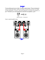
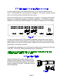
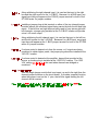
B & K Components Ltd.
P/N 12687
B&K Components, Ltd., 2100 Old Union Road, Buffalo, New York 14227
Safety Precautions
Page 2
Purpose and function
Page 3
Design and construction
Page 3
Features
Page 4
Rear panel view
Page 4
Rear panel description
Page 5
Control muting
Page 5 - 6
Level controls
Page 6
Inputs
Page 7
Outputs
Page 8
Internal Bus
Page 9
Jumper description
Page 9 - 10
Mono application
Page 11
Bridged application
Page 12
System installation
Page 13
Making the connection
Page 13 - 14
Troubleshooting
Page 15
Care and cleaning
Page 15
Specifications
Page 16
Warranty
Page 17
Manual and Power cord
Page 1
WARNING: TO PREVENT FIRE OR SHOCK HAZARD, DO NOT EXPOSE THIS UNIT
TO RAIN OR MOISTURE.
The lightning flash with arrowhead, within an equilateral triangle, is intended to alert the
user of the presence of uninsulated “dangerous voltage” within the product’s enclosure
that may be sufficient magnitude to constitute a risk of electric shock to you.
The exclamation point within an equilateral triangle is intended to alert the user of the
presence of important operating and maintenance (servicing) instructions in the
literature accompanying the unit.
Observance of polarity is essential. Double-check connections before turning
the amplifier on. The amplifier can be damaged if polarities are incorrect.
Damage can occur to your speakers if the power rating* of each individual driver
is exceeded by the amplifier. Ensure that all the drivers in your speaker system
are capable of handling not only the power being delivered by the amplifier, but
the energy that is likely to be generated during strong passages.
Turn amplifier ‘off’ when plugging in or unplugging input and speaker cables!!!
The ST1200 series II is equipped with raised feet so that continuous ventilation
can be maintained. They help to maintain acoustic feedback into the amplifier at
a minimum. They also provide a measure of protection against scratching any
surface the unit might be resting on.
Do not stack anything on top of the amplifier (preamplifier, processor,
source...etc.).
Leave at least 2-3 inches clearance from the top of the amplifier to the next shelf,
component, etc., to ensure proper ventilation.
* If you are at all unsure of what the speaker ‘ratings’ are, contact your dealer.
Page 2
The ST1200 series II is a compact, very efficient, two channel power amplifier. It is
designed to be used in all types of audio or audio/video systems. The term versatile is
almost adequate to describe the variance of operational modes the ST1200 series II is
capable of providing. This is all accomplished through the simple placement of internal
jumpers and the paralleling or bridging of it’s outputs and/or linking multiple ST1200
series II’s.
Here is a listing for some of the many tasks it can be set up to perform:
&
The most obvious function for the ST1200 series II is to take 2 separate
audio inputs, such as a stereo pair, and provide 2 separate amplified
outputs. Your ST1200 series II has arrived set up in this configuration.
&
With the inputs buffered, a line output (OUT BUS) may be taken from
either the L BUS, R BUS, or L+R BUS and sent on to another amplifier.
This allows for linking of multiple amplifiers.
&
Continuing its versatility, the ST1200 series II may be used mono to
provide one, medium current channel in order to drive a speaker requiring
more power.
&
As a result of the ST1200 series II’s unique bus system, the input to the
left channel may be inverted thereby allowing the possibility of creating a
single high voltage (bridged) channel from one source, through the left
bus.
The ST1200 series II utilizes high quality electronic circuitry to achieve an environment
wherein a detailed, transparent, and highly musical sound can be realized. The high
quality parts complement include state-of-the-art solid state devices, 1% metal film
resistors, computer grade electrolytic power supply capacitors, and a high capacity
toroidal transformer.
Page 3
- Efficient high current transformer for improved dynamics.
- More accurate and three dimensional reproduction of source
material.
- Provides short term protection from accidental shorting of output
devices and protection from thermal overload.
- Improve connections for better sound and minimized signal
loss and degradation.
- Low noise resistors for better sound and a greater degree
of repeatability.
- Ability to reproduce demanding recordings.
- Large capacity computer grade electrolytic capacitors
for extended low frequency control and improved dynamics.
1. AC fuse holder
5. Line Level outputs
2. AC Input receptacle
6. RCA inputs
3. Speaker outputs
7. Level controls
4. Amplifier control muting input/output
Page 4
1. AC fuse holder -
Holds the AC Line fuse. This fuse is an 8 Amp / 250 Volt
Slow Blow fuse. Replace with same type and value fuse
only.
2. AC Input receptacle - For attaching the supplied AC power cord to the
amplifier.
3. Speaker outputs -
For connecting the speakers to the amplifier. Explained
further on page 8.
4. Amplifier control muting input/output To provide remote switching of mute on/off of the amplifier.
Explained further on page 5.
5. Line level outputs -
For connecting signal to another amplifier (daisy chaining).
6. RCA inputs -
For connecting signal patch cables (interconnects) from the
preamplifier to the amplifier to pass signal.
7.Level controls -
For adjusting the input level to the amplifier. Explained
further on page 6.
A control is provided on each ST1200 series II amplifier to allow remote switching of
mute on/off. The preamplifier’s control output, such as is provided with B&K series
preamplifiers, can be utilized to provide a control signal to the ST1200 series II. If more
than one amplifier is being controlled, the control signal can be extended to include
each successive unit by simply running an RCA type audio cable from the CTRL OUT
connector of the first amplifier to the CTRL IN connector of the next unit (commonly
referred to as ‘daisy chaining’). An example of how to connect two amplifiers is
illustrated in figure B.
If a source other than a B&K series preamplifier is used to control multiple amplifiers,
only the control output voltage from the source is critical. It must be within the range, as
indicated on the rear panel, 5-24 volts DC is required. The amplifier will provide each
successive amplifier with a control voltage of 12 volts DC for reliable operation. The
amplifiers control output may be used as a source of 12 VDC @ 125 mA for other user
applications as well.
Page 5
If the control function is desired, each unit in the system must remain connected at all
times and the control must be enabled. To enable the control function, the CTRL
ENABLE button must be out for each controllable amplifier in the system. For more
information on the amplifiers output status under various control conditions, refer to the
table below.
@ CTRL IN
Button position
Output status
@ CTRL OUT
Signal
OUT
Sound
Signal
Signal
IN
Sound
Signal
No Signal
OUT
Mute
No Signal
No Signal
IN
Sound
Signal
There are two level controls on the back of the amplifier. One level control for each
channel.
When using the level controls, first start with them turned all the way up (clockwise).
Then adjust them according to your system requirements to match the sound level
coming from each speaker. This is a rough adjustment for matching different driver
impedances. Any fine tuning should be done by the preamplifier.
Page 6
Example: When using 4 ohm and 8 ohm speakers together, the 4 ohm may sound
louder then 8 ohm at a given volume level. The level controls on the amplifier are used
to match the speakers volume level. Clockwise will increase the output. Counter
clockwise will decrease the output.
RCA type connectors accept line input from the preamplifier’s unbalanced output
connectors. There are two input connectors, one for each channel, that may be used to
connect the amplifier to the preamplifier.
RCA cable connector -
Here is a typical input setup:
You will notice the OUT BUS connections shown above. You may use these to connect
to another amplifier. The L BUS OUT carries the same signal as the L INPUT. The R
BUS OUT carries the same signal as the R INPUT. The L+R BUS OUT carries the
combined signal from the left and right inputs.
Page 7
Five way binding posts are provided. One pair for each channel. They are designed to
accept a banana-type plug or spade lug connector (shown below) and are color coded
for easy identification. The red (+) post should always be connected to the speakers (+)
jack. The black (-) post should always be connected to the speakers (-) jack.
Spade connector
Banana jack
Here is a typical amplifier setup:
Page 8
In order to gain access to the internal bus structure, you must first remove the top
cover. Turn the amplifier so the rear panel is facing your. The jumper modules may be
seen on the circuit board just behind the level controls.
Below is the default setup for the ST1200 series II amplifier. By arranging the jumpers
allows you to configure the amplifier for different applications. If you wish to use the
amplifier as a stereo (two channel) amplifier, you need not change any of the settings.
In order to reconfigure the ST1200 series II’s channels, remove the source control
group jumper from its present position (if necessary) and install it on the terminal you
wish to select as the source for that channel. Make sure it has been inserted on both
terminal pins of the jumper modules.
To complete the configuration, the volume group jumper should be placed at either the
‘USE VOL’ or ‘NO VOL’ terminal depending on you configuration.
Figure G illustrates the jumper modules used in
configuring each channel. Each jumper terminal
location is conveniently labeled as to the source it
can be configured to provide. Explained further on
the following page.
Page 9
Along with being the right channel input, it is used as the input to the right
bus and the right source for the ‘L+R BUS’. Because it is a BUS input, any
signal input here will appear at the ‘R BUS’ jumper terminal for both of the
ST1200 series II’s jumper modules.
Installing a jumper plug at this terminal on either of the two internal jumper
modules selects the combined signal being carried by both the left and right
inputs. If the left bus and right bus are being used to carry stereo right and
left channels, a jumper plug installed at the ‘L+R BUS’ location will provide
a true L+R mono output.
Along with being the left channel input, it is used as the input to the left bus
and the left source for the ‘L+R BUS’. Because it is a BUS input, any signal
input here will appear at the ‘L BUS’ jumper terminal for both of the ST1200
series II’s jumper modules.
If volume control is desired only from the source, or if outputs are being
combined to obtain higher power, the jumper plug should be installed at the
‘NO VOL’ location.
If volume control is desired at the amplifier, beyond that provided at the
source, a shorting plug is installed at the ‘USE VOL’ location. The ‘USE
VOL’ setting
be used when channels are bridged or
combined.
This is a single jumper module that is set apart, up and to the right from the
channel jumper modules on the circuit board. It provides a special function,
when the jumper is set on the ‘-L’ pins, the left bus signal feeding the left
channel will be inverted.
Page 10
The ST1200 series II’s two output channels may be paralleled (mono) to combine the
left and right channels output current. This feature allows the amplifier to double its
apparent output current. To use, place the source group jumper for both channels on
the ‘L BUS’ jumper terminal. Place the volume group jumper for both channels on the
‘NO VOL’ jumper terminal.
The speaker output terminals on the ST1200 series II’s rear panel must be paralleled in
order to complete the setup. Simply connect the (+) terminals for both channels
together using a jumper wire (not supplied with the amplifier). Finally, connect the
speaker cables from the left channels (+) and (-) terminals to the speakers. Input your
source signal into the left channel input. The instructions show the use of the left
channel. You may also use the right channel if you desire, just follow the above
instructions using the right channel. You may also use the L+R BUS to send a mono
signal out of the amplifier derived from the left and right channels. See below:
Page 11
The ST1200 series II may be bridged to drive a high impedance speaker. To use,
place the source group jumper for both channels on the ‘L BUS’ jumper terminal. Place
the volume group jumper for both channels on the ‘NO VOL’ jumper terminal. Place the
jumper module on the ‘-L’ terminal.
Finally, connect the speakers (+) to the right channels (+) terminal and the speakers (-)
to the left channels (+) terminal. Input your source signal into the left channel input
).
(
Page 12
There will most likely be a number of cables involved in the installation of your home
entertainment system. Pre-planning is essential in order to maximize system efficiency.
We recommend the following as a means of helping you reach that goal:
Make a diagram of your proposed system by laying out the relative location of
each component in the system. Then lay out the proposed cable runs between
them. Number each cable and record its length on the diagram for future
reference.
Cable runs are critical in that they must be kept away from sources of power
radiation (amplifiers, power cords, heaters, etc...). For the sake of safety, they
should also be kept out of traffic areas.
The process of optimizing the system will include the type of cable, the length of
the run, and the obstructions it must deal with along its run. Your dealer can
advise you on the products available and their relative merits. If building custom
length audio cables is not your strength, your dealer should be able to help you
with that as well.
When possible, use a separate AC power line for the amplifier, one that is not
shared by any other component in the system of any other house hold
component.
Before doing anything, ensure that the power switch on the amplifier’s front panel
is in the ‘off’ position. Again, it is recommended that you locate a separate AC
power outlet for the amplifier, one that is
shared by any other audio
component in the system or any other house hold component. This will eliminate
the possibility of the amplifier ‘modulating’ the power being supplied to the
component and compromising the signal originating from that component.
Locate the AC power cord provided with the amplifier and plug it into the power
input receptacle in the rear panel.
Connect the audio cables from your preamplifier’s output to the corresponding
input connector on the amplifier.
Page 13
Connect the wires from your speakers to the appropriate output on the amplifier.
It is absolutely essential that you observe correct polarity in these connections.
Double check all connections.
Plug the amplifier’s power cord into the AC power source. Turn the amplifier’s
power switch ‘on’. The panel light should be illuminated. Leave the preamplifier
turned off. Before proceeding to the next step turn the amplifier off and wait 30
seconds for the amplifier to discharge. Both the preamplifier and amplifier
should be off.
Connect a playback unit (CD, VLD, Tuner, etc...) to the preamplifier. Turn the
volume on the preamplifier to minimum. Turn on the preamplifier, then the
amplifier (in that order). Set source on the preamplifier to the playback unit
you’ve just connected. Turn volume up slowly and music should be heard from
all channels. If this is not the case, double check your installation.
Should you encounter any problems that cannot be traced to the source or the
material being played, consult the “TROUBLESHOOTING” section on page 15.
Page 14
PROBLEM
No sound
(‘on’ LED not illuminated)
POSSIBLE CAUSE
1.
2.
3.
4.
No sound on some or all
selected channels (‘on’
LED illuminated)
1.
2.
3.
4.
POSSIBLE SOLUTION
Power cord not plugged in.
Power off at AC source.
AC power inlet fuse blown
or faulty.
Control switch in the wrong
position.
1.
2.
3.
Speaker leads loose or
faulty.
Line stage to amp. cables
loose. or faulty.
Source to line stage cables
loose or faulty.
Line stage or source not
correctly selected.
1.
4.
2.
3.
4.
Reconnect power cord.
Check AC switch or fuse.
Check for shorts or
overloading.
Place control switch in
proper position. (Page 5)
Tighten, repair, or
replace cable.
Tighten, repair or replace
cable.
Tighten, repair or replace
cable.
Check all switch settings.
Sound lacks direction,
bass weak
1.
Speakers connected out of
phase.
1.
Check connections
making sure that cables
are connected (+) to (+)
and (-) to (-).
Loud hum or buzz on one
or more channels
1.
Poor ground connection in
interconnect cables.
1.
Check all connectors and
repair as necessary.
Low output from amplifier
1.
Balanced switch in
balanced mode when
using unbalanced inputs.
1.
Put balanced switch in
correct position.
Channel sounds distorted
and low in output
1.
Blown rail fuse.
1.
Replace blown rail fuse
inside amplifier.
** Note: If unit continues to blow power inlet fuses,
have it serviced.
Under normal use, the amplifier will not require any special care. Over time you may
wish to clean the exterior of the unit by wiping it with a damp cloth to remove any dirt or
dust that accumulates on it. Do not let any liquid enter the amplifier thru the vents in
the top cover. You may clean the connectors on the rear panel with isopropyl alcohol
annually.
Page 15
Power rating: 8 ohms
4 ohms
60 watts @ 1 kHz
Not recommended
Frequency response
5 Hz - 45 kHz
Input sensitivity
0.77 Volts
THD (S+N)
0.09 % @ 1 kHz
Input impedance
33.2 k ohms
Damping factor
100
Current (peak to peak)
20 Amps
Slew rate
14 V / )sec
Dynamic headroom
1.4 dB
S/N (A-weighted)
95 dB
Voltage gain
28
Line voltage
120/220/240 VAC switchable
Dimensions (O.A.)
17"(w) X 12"(d) X 3.75"(h)
Weight
23 lbs
Power consumption
210 watts max
2.3 Amps max current draw
15 watts @ no input
Replacement fuses
Line - 8 Amp/250 Volt Slow Blow
Rails - 4 Amp/250 Volt Slow Blow
Page 16
B&K Components Ltd., referred to herein as B&K, warrants your B&K equipment against all defects in
material and workmanship for a period of five years from the date of purchase. This warranty applies
only to the original purchaser and only to equipment in normal residential use and service. Defective
equipment must be returned to B&K, prepaid, accompanied by sufficient payment to cover the cost of
return shipping and handling, and will be repaired or replaced at the discretion of B&K whose decision
as to the method of reparation will be final.
This warranty shall not apply to any equipment which is found to have been improperly installed,
incorrectly fused, misused, abused, or subjected to harmful elements, used in any way not in
accordance with instructions supplied with the unit, or to have been modified, repaired or altered in any
way without the expressed, written consent of B&K. This warranty does not apply to the cabinet, the
remote controller, or appearance items such as the faceplate, control buttons, or display lenses, nor
does it cover any expenses incurred in shipping the unit to and from the manufacturer’s service depot.
No warranty, implied or otherwise created by State law shall extend beyond the terms of this warranty
and B&K shall not be liable for any incidental or consequential damage arising out of a defect in material
or workmanship of the unit during the terms of this warranty or thereafter. Some States do not allow the
exclusion or limitation of incidental or consequential damages and the foregoing exclusions may not
apply to you.
This warranty gives you specific legal rights. Your may also have other rights which vary from State to
State.
No agent, representative, dealer or employee of B&K has the authority to increase or alter the
obligations or terms of this warranty.
B&K Components Ltd.
No equipment may be returned to B&K Components Ltd. Without a RETURN AUTHORIZATION.
Should you find it necessary to return equipment to B&K, for any reason, a RETURN AUTHORIZATION
(RA) number must be issued by B&K in respect of the equipment being returned. You may request an
RA number by calling B&K at the numbers below. We ask that you provide the following information at
that time.
1.
2.
3.
Your name, address, and phone number.
The model and serial number of the equipment being returned.
A description of the problem being experienced.
Your call will be referred to a Technical Service Representative who will work with you to resolve the
problem. If it is determined that the unit must be returned for repair, an RA number will be issued.
B&K Components Ltd. 2100 Old Union Road, Buffalo New York 14227
1-800-543-5252 or 1-716-656-0023
Page 17
B&K Components, Ltd.
2100 Old Union Road
Buffalo, New York 14227
716-656-0023
www.bkcomp.com