1
Part No. P0607274 01
September 17, 2003
Business Communications Manager
UPS Installation and Configuration
Guide
2
Copyright © 2003 Nortel Networks
All rights reserved. July, 2003.
The information in this document is subject to change without notice. The statements, configurations, technical data, and
recommendations in this document are believed to be accurate and reliable, but are presented without express or implied
warranty. Users must take full responsibility for their applications of any products specified in this document. The
information in this document is proprietary to Nortel Networks NA Inc.
Trademarks
NORTEL NETWORKS and Business Communications Manager, are trademarks of Nortel Networks NA Inc.
Microsoft, MS, MS-DOS, Windows, and Windows NT are registered trademarks of Microsoft Corporation.
APC are registered trademarks of American Power Conversion, Inc.
All other trademarks and registered trademarks are the property of their respective owners.
North American Regulatory Information
Safety
Business Communications Manager equipment meets all applicable requirements of both the CSA
C22.2 No. 950-95 and UL-1950 Edition 3.
Danger: Risk of shock.
Read and follow installation instructions carefully.
Ensure the Business Communications Manager and Business Communications Manager
expansion unit are unplugged from the power socket and that any telephone or network
cables are unplugged before opening the Business Communications Manager or Business
Communications Manager expansion unit.
If installation of additional hardware and /or servicing is required, disconnect all telephone
cable connections prior to unplugging the Business Communications Manager.
Ensure the Business Communications Manager and Business Communications Manager
expansion unit are plugged into the wall socket using a three-prong power cable before
any telephone cables are connected.
P0607274 01
3
Caution: Only qualified persons should service the system.
The installation and service of this hardware is to be performed only by service personnel
having appropriate training and experience necessary to be aware of hazards to which they
are exposed in performing a task and of measures to minimize the danger to themselves or
other persons.
Electrical shock hazards from the telecommunication network and AC mains are possible
with this equipment. To minimize risk to service personnel and users, the Business
Communications Manager system must be connected to an outlet with a third-wire ground.
Service personnel must be alert to the possibility of high leakage currents becoming
available on metal system surfaces during power line fault events near network lines. These
leakage currents normally safely flow to Protective Earth ground via the power cord.
Therefore, it is mandatory that connection to an earthed outlet is performed first and
removed last when cabling to the unit. Specifically, operations requiring the unit to be
powered down must have the network connections (central office lines) removed first.
Radio-frequency Interference
Warning: Equipment generates RF energy.
This equipment generates, uses, and can radiate radio-frequency energy. If not installed
and used in accordance with the installation manual, it may cause interference to radio
communications. It has been tested and found to comply with the limits for a Class A
computing device pursuant to Part 15 of the FCC Rules and with ICES.003, CLASS A
Canadian EMI Requirements. Operation of this equipment in a residential area is likely to
cause interference, in which case the user, at his or her own expense, will be required to
take whatever measures may be required to correct the interference.
UPS Installation and Configuration Guide
4
Telecommunication Registration
Business Communications Manager equipment meets all applicable requirements of both Industry
Canada CS-03 and US Federal Communications Commission (FCC) Part 68 and has been
registered under files Industry Canada 332D-5980A and FCC US:AB6KF15B20705 (key system),
US:AB6MF15B20706 (hybrid system), and US:AB6PF15B23740 (PBX system). Connection of
the Business Communications Manager telephone system to the nationwide telecommunications
network is made through a standard network interface jack that you can order from your local
telecommunications company. This type of customer-provided equipment cannot be used on party
lines or coin lines.
Before installing this equipment, users should ensure that it is permissible to be connected to the
facilities of the local telecommunications company. The equipment must also be installed using an
acceptable method of connection. The customer should be aware that compliance with the above
conditions may not prevent degradation of service in some situations.
Repairs to certified equipment should be made by an authorized maintenance facility designated
by the supplier. Any repairs or alterations made by the user to this equipment, or equipment
malfunctions, may give the telecommunications company cause to request the user to disconnect
the equipment. Users should ensure for their own protection that the electrical ground connections
of the power utility, telephone lines and internal metallic water pipe system, if present, are
connected together. This precaution may be particularly important in rural areas.
Caution: Users should not attempt to make such connections themselves, but
should contact the appropriate electric inspection authority, or electrician.
Electromagnetic Compatibility
Business Communications Manager equipment meets all FCC Part 15, Class A radiated and
conducted emissions requirements.
Business Communications Manager does not exceed the Class A limits for radiated and conducted
emissions from digital apparatus as set out in the Radio Interference Regulations of Industry
Canada.
Telephone Company Registration
It is usually not necessary to call the telecommunications company with information on the
equipment before connecting the Business Communications Manager system to the telephone
network. If the telecommunications company requires this information, provide the following:
•
•
•
•
•
telephone number(s) to which the system will be connected
FCC registration number (on label affixed to Business Communications Manager)
universal service order code (USOC)
service order code (SOC)
facility interface code (FIC)
P0607274 01
5
Rights of the Telecommunications Company
If the Business Communications Manager system or adjunct systems is causing harm to the
telephone network, the telecommunications company may discontinue service temporarily. If
possible, the telecommunications company will notify you in advance. If advance notice is not
practical, the user will be notified as soon as possible. The user will be given the opportunity to
correct the situation and informed of the right to file a complaint to the FCC.
The telecommunications company may make changes in its facilities, equipment, operations or
procedures that could affect the proper functioning of the system. If this happens, the
telecommunications company will give you advance notice in order for you to make any necessary
modifications to maintain uninterrupted service.
Repairs
In the event of equipment malfunction, all repairs to certified equipment will be performed by an
authorized supplier.
Canadian Regulations - please read carefully
Notice
The term "IC" before the certification number located on the host equipment only signifies that the
Industry Canada technical specifications were met. The Department does not guarantee the
equipment will operate to the user's satisfaction. Before installing this equipment, users should
ensure that it is permissible to be connected to the facilities of the local telecommunications
company. The equipment must also be installed using an acceptable method of connection. The
customer should be aware that compliance with the above conditions may not prevent degradation
of service in some situations. Repairs to certified equipment should be coordinated by a
representative designated by the supplier. Any repairs or alterations made by the user to this
equipment, or equipment malfunctions, may give the telecommunications company cause to
request the user to disconnect the equipment. Users should ensure for their own protection that the
electrical ground connections of the power utility, telephone lines and internal metallic water pipe
system, if present, are connected together. This precaution may be particularly important in rural
areas.
Caution: Users should not attempt to make such connections themselves, but should
contact the appropriate electric inspection authority, or electrician, as appropriate.
Notice
The Ringer Equivalence Number (REN) assigned to each terminal device provides an indication of
the maximum number of terminals allowed to be connected to a telephone interface. The
termination on an interface may consist of any combination of devices subject only to the
requirement that the sum of the RENs of all the devices does not exceed 5.
UPS Installation and Configuration Guide
6
This Class A device complies with Part 68 & Part 15 of the FCC Rules and ICES-003 Class A
Canadian EMI requirements. Operation is subject to the following two conditions (1) This device
may not cause harmful interference and (2) this device must accept any interference received,
including interference that may cause undesired operation.
Do not attempt to repair this equipment. If you experience trouble, write for warranty and repair
information:
Nortel Networks
30 Norelco Drive, Weston, Ontario
M9L 2X6 Canada
US Regulations - please read carefully
Federal Communications Commission (FCC) Notice
FCC registration number: This telephone equipment complies with Part 68, Rules and
Regulations, of the FCC for direct connection to the Public Switched Telephone Network. (The
FCC registration number appears on a sticker affixed to the bottom of the telephone.)
Your connection to the telephone line must comply with these FCC rules:
•
•
•
•
•
An FCC compliant telephone cord and modular plug is provided with this equipment. This
equipment is designed to be connected to the telephone network premises wiring using a
compatible modular jack which is Part 68 compliant. See installation instructions for details.
Use only an FCC Part 68-compliant Universal Service Order Code (USOC) network interface
jack, as specified in the installation instructions, to connect this telephone to the telephone
line. (To connect the phone, press the small plastic tab on the plug at the end of the phone’s
line cord. Insert into a wall or baseboard jack until it clicks. To disconnect, press the tab and
pull out.) See installation instructions for details.
If the terminal equipment causes harm to the telephone network, the telephone company will
notify you in advance that temporary discontinuance of the product may be required. But if
advance notice isn’t practical, the telephone company will notify you as soon as possible. You
will also be advised of your right to file a complaint with the FCC, if you believe it is
necessary.
If a network interface jack is not already installed in your location, you can order one from
your telephone company. Order the appropriate USOC Network interface jack, as specified in
the installation instructions, for wall-mounted telephones or for desk/table use. In some states,
customers are permitted to install their own jacks.
Your telephone may not be connected to a party line or coin telephone line. Connection to
Party Line Service is subject to state tariffs. (Contact the state public utility commission,
public service commission or corporation commission for information.)
P0607274 01
7
•
•
It is no longer necessary to notify the Telephone Company of your phone’s Registration and
REN numbers. However, you must provide this information to the telephone company if they
request it. The telephone company may make changes in its facilities, equipment, operation or
procedures that could affect the operation of the equipment. If this happens the telephone
company will provide advance notice in order for you to make necessary modification to
maintain uninterrupted service.
Do not attempt to repair this equipment. If you experience trouble, write for warranty and
repair information:
Nortel Networks
640 Massman Drive,
Nashville, TN, 37210, USA
Important Safety Instructions
The following safety instructions cover the installation and use of the Product. Read carefully and
retain for future reference.
Installation
When installing your UPS equipment, basic safety precautions should always be followed to
reduce risk of fire, electric shock and injury to persons, including the following:
Warning: To avoid electrical shock hazard to personnel or equipment damage observe the
following precautions when installing telephone equipment:
1
Never install the UPS or other equipment during a lightning storm.
2
Never install the UPS in wet locations.
This symbol on the product is used to identify the following important information: Use only
with a CSA or UL certified CLASS 2 level C power supply.
Use
When using your UPS equipment, basic safety precautions should always be followed to reduce
risk of fire, electric shock and injury to persons, including the following:
1
Read and understand all instructions.
2
Follow the instructions marked on the product.
3
Unplug this product from the wall outlet before cleaning. Do not use liquid cleaners or aerosol
cleaners. Use a damp cloth for cleaning.
4
Do not use this product near water, for example, near a bath tub, wash bowl, kitchen sink, or
laundry tub, in a wet basement, or near a swimming pool.
5
Do not place this product on an unstable cart, stand or table. The product may fall, causing
serious damage to the product.
UPS Installation and Configuration Guide
8
6
This product should never be placed near or over a radiator or heat register. This product
should not be placed in a built-in installation unless proper ventilation is provided.
7
Do not allow anything to rest on the power cord. Do not locate this product where the cord will
be abused by persons walking on it.
8
Do not overload wall outlets and extension cords as this can result in the risk of fire or electric
shock.
9
Never spill liquid of any kind on the product.
10 To reduce the risk of electric shock do not disassemble this product, but have it sent to a
qualified service person when some service or repair work is required.
11 Unplug this product from the wall outlet and refer servicing to qualified service personnel
under the following conditions:
a
When the power supply cord or plug is damaged or frayed.
b
If the product has been exposed to rain, water or liquid has been spilled on the product,
disconnect and allow the product to dry out to see if it still operates; but do not open up the
product.
c
If the product housing has been damaged.
d
If the product exhibits a distinct change in performance.
12 Caution: To eliminate the possibility of accidental damage to cords, plugs and jacks, do not use
sharp instruments during the assembly procedures.
13 Save these instructions.
Safety
WARNING!
Only qualified service personnel may install this equipment. The instructions in this
manual are intended for use by qualified service personnel only.
Risk of shock.
Ensure the Business Communications Manager is unplugged from the power socket
before installing the UPS device.
Read and follow installation instructions carefully
P0607274 01
9
Only qualified persons should service the system.
The installation and service of this hardware is to be performed only by service
personnel having appropriate training and experience necessary to be aware of
hazards to which they are exposed in performing a task and of measures to minimize
the danger to themselves or other persons.
Electrical shock hazards from the telecommunication network and AC mains are
possible with this equipment. To minimize risk to service personnel and users, the
UPS device must be connected to an outlet with a third-wire Earth.
Service personnel must be alert to the possibility of high leakage currents becoming
available on metal system surfaces during power line fault events near network lines.
These leakage currents normally safely flow to Protective Earth via the power cord.
Therefore, it is mandatory that connection to an earthed outlet is performed first and
removed last when cabling to the unit. Specifically, operations requiring the unit to be
powered down must have the network connections (exchange lines) removed first.
UPS Installation and Configuration Guide
10
P0607274 01
11
Contents
North American Regulatory Information . . . . . . . . . . . . . . . . . . . . . . . . . . . . . . . . . . . . . . . . . 2
Safety . . . . . . . . . . . . . . . . . . . . . . . . . . . . . . . . . . . . . . . . . . . . . . . . . . . . . . . . . . . . . . . . 2
Radio-frequency Interference . . . . . . . . . . . . . . . . . . . . . . . . . . . . . . . . . . . . . . . . . . . . . . 3
Telecommunication Registration . . . . . . . . . . . . . . . . . . . . . . . . . . . . . . . . . . . . . . . . . . . . 4
Electromagnetic Compatibility . . . . . . . . . . . . . . . . . . . . . . . . . . . . . . . . . . . . . . . . . . . . . . 4
Telephone Company Registration . . . . . . . . . . . . . . . . . . . . . . . . . . . . . . . . . . . . . . . . . . . 4
Rights of the Telecommunications Company . . . . . . . . . . . . . . . . . . . . . . . . . . . . . . . . . . 5
Repairs . . . . . . . . . . . . . . . . . . . . . . . . . . . . . . . . . . . . . . . . . . . . . . . . . . . . . . . . . . . . . . . 5
Canadian Regulations - please read carefully . . . . . . . . . . . . . . . . . . . . . . . . . . . . . . . . . 5
US Regulations - please read carefully . . . . . . . . . . . . . . . . . . . . . . . . . . . . . . . . . . . . . . . 6
Federal Communications Commission (FCC) Notice . . . . . . . . . . . . . . . . . . . . . . . . . 6
Important Safety Instructions . . . . . . . . . . . . . . . . . . . . . . . . . . . . . . . . . . . . . . . . . . . 7
Safety . . . . . . . . . . . . . . . . . . . . . . . . . . . . . . . . . . . . . . . . . . . . . . . . . . . . . . . . . . . . . . . . 8
Preface . . . . . . . . . . . . . . . . . . . . . . . . . . . . . . . . . . . . . . . . . . . . . . . . . . . . . . . . . . 13
Display Tips . . . . . . . . . . . . . . . . . . . . . . . . . . . . . . . . . . . . . . . . . . . . . . . . . . . . . . . . . . . . . . 13
Symbols used in this guide . . . . . . . . . . . . . . . . . . . . . . . . . . . . . . . . . . . . . . . . . . . . . . . . . . 14
Text conventions . . . . . . . . . . . . . . . . . . . . . . . . . . . . . . . . . . . . . . . . . . . . . . . . . . . . . . . . . . 15
Related publications . . . . . . . . . . . . . . . . . . . . . . . . . . . . . . . . . . . . . . . . . . . . . . . . . . . . . . . 15
How to Get Help . . . . . . . . . . . . . . . . . . . . . . . . . . . . . . . . . . . . . . . . . . . . . . . . . . . . . . . . . . 16
Chapter 1
Uninterruptable Power Supply (UPS) Overview . . . . . . . . . . . . . . . . . . . . . . . . . 17
UPS Overview . . . . . . . . . . . . . . . . . . . . . . . . . . . . . . . . . . . . . . . . . . . . . . . . . . . . . . . . . . . . 17
BCM and UPS power and control connections . . . . . . . . . . . . . . . . . . . . . . . . . . . . . . . . 18
UPS threshold values . . . . . . . . . . . . . . . . . . . . . . . . . . . . . . . . . . . . . . . . . . . . . . . . . . . 19
Alarm and event reporting . . . . . . . . . . . . . . . . . . . . . . . . . . . . . . . . . . . . . . . . . . . . . . . . 19
Operational measurements and accounting . . . . . . . . . . . . . . . . . . . . . . . . . . . . . . . . . . 22
Log files and traces . . . . . . . . . . . . . . . . . . . . . . . . . . . . . . . . . . . . . . . . . . . . . . . . . 22
UPS default configuration settings . . . . . . . . . . . . . . . . . . . . . . . . . . . . . . . . . . . . . . . . . 22
Chapter 2
Install and Initialize the Uninterruptable Power Supply . . . . . . . . . . . . . . . . . . . 25
Install and initialize the UPS . . . . . . . . . . . . . . . . . . . . . . . . . . . . . . . . . . . . . . . . . . . . . . . . . 25
Procedure:
Install the UPS . . . . . . . . . . . . . . . . . . . . . . . . . . . . . . . . . . . . . . . . . . . . . . . . . . . . . . . 25
Procedure:
Initialize the serial port . . . . . . . . . . . . . . . . . . . . . . . . . . . . . . . . . . . . . . . . . . . . . . . . . 26
UPSConsoleToggle Service . . . . . . . . . . . . . . . . . . . . . . . . . . . . . . . . . . . . . . . . . . . . . . . . . 27
Procedure:
Enable UPSConsoleToggle: . . . . . . . . . . . . . . . . . . . . . . . . . . . . . . . . . . . . . . . . . . . . . 27
Procedure:
Enable the console (batch file): . . . . . . . . . . . . . . . . . . . . . . . . . . . . . . . . . . . . . . . . . . 28
UPS Installation and Configuration Guide
12
Chapter 3
Monitor the Uninterruptable Power Supply . . . . . . . . . . . . . . . . . . . . . . . . . . . . . 29
Monitor the UPS . . . . . . . . . . . . . . . . . . . . . . . . . . . . . . . . . . . . . . . . . . . . . . . . . . . . . . . . . . 29
Procedure:
Access the UPS Status monitor . . . . . . . . . . . . . . . . . . . . . . . . . . . . . . . . . . . . . . . . . . 30
Procedure:
Access the UPS OM and log reports . . . . . . . . . . . . . . . . . . . . . . . . . . . . . . . . . . . . . . 31
Procedure:
Access the UPS status report . . . . . . . . . . . . . . . . . . . . . . . . . . . . . . . . . . . . . . . . . . . 33
Procedure:
Test the UPS . . . . . . . . . . . . . . . . . . . . . . . . . . . . . . . . . . . . . . . . . . . . . . . . . . . . . . . . 34
Figures
Figure 1
Acrobat Reader display setup selections . . . . . . . . . . . . . . . . . . . . . . . . . . . . . . 14
Figure 2
UPS / BCM power connections and topology . . . . . . . . . . . . . . . . . . . . . . . . . . 18
Figure 3
UPS configuration setup screen display . . . . . . . . . . . . . . . . . . . . . . . . . . . . . . 26
Figure 4
UPS Status monitor screen display . . . . . . . . . . . . . . . . . . . . . . . . . . . . . . . . . . 30
Figure 5
UPS OMs report . . . . . . . . . . . . . . . . . . . . . . . . . . . . . . . . . . . . . . . . . . . . . . . . . 31
Figure 6
UPS Log file report . . . . . . . . . . . . . . . . . . . . . . . . . . . . . . . . . . . . . . . . . . . . . . . 32
Figure 7
UPS status report . . . . . . . . . . . . . . . . . . . . . . . . . . . . . . . . . . . . . . . . . . . . . . . . 33
Tables
Table 1
UPS Event messages . . . . . . . . . . . . . . . . . . . . . . . . . . . . . . . . . . . . . . . . . . . . 20
Table 2
UPS default settings . . . . . . . . . . . . . . . . . . . . . . . . . . . . . . . . . . . . . . . . . . . . . . 22
P0607274 01
13
Preface
This guide describes how to install, initialize and monitor the Business Communications Manager
Uninterruptable Power Supply (UPS) device.
Information in these chapters explains:
•
•
•
how to set up the UPS
how to start and initialize the UPS
how to test and monitor the UPS
Display Tips
You can read this publication from your computer monitor or printed hard copy. For best on-screen
display results, use Adobe Acrobat Reader (TM) version 4.0 or 5.0.
If you use Adobe Acrobat Reader, version 4.0, perform the following to optimize the illustrations:
•
•
Increase display magnification
Print the document
For Adobe Acrobat Reader, version 5.0, perform the following steps to optimize the graphical
display:
1
Start the Adobe Acrobat Reader, version 5.0 application.
2
From the top line menu, select: Edit -->Preferences -->General.
3
Select Display, from the preferences menu at the left side of the setup screen.
4
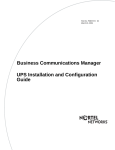
Select the following smoothing options from the Display setup screen:
•
•
•
Smooth Text
Smooth Line Art
Smooth Images
See Figure 1 to review Acrobat Reader version 5.0 display selections.
UPS Installation and Configuration Guide
14
Preface
Figure 1 Acrobat Reader display setup selections
Symbols used in this guide
This guide uses the following symbols to draw your attention to important information:
Caution: Caution Symbol
Alerts you to conditions where you can damage the equipment.
Danger: Electrical Shock Hazard Symbol
Alerts you to conditions where you can get an electrical shock.
Warning: Warning Symbol
Alerts you to conditions where you can cause the system to work improperly or to fail.
Note: Note Symbol
Alerts you to important information.
P0607274 01
Preface
15
Tip: Tip Symbol
Alerts you to additional information that can help you perform a task.
Warning: Grounding Symbol.
Alerts you to ground yourself with an antistatic grounding strap before performing the
maintenance procedure.
Warning: Disconnect Symbol
Alerts you to remove the Business Communications Manager and Business
Communications Manager expansion cabinet power cords from the AC outlet before
performing any maintenance procedure.
Text conventions
This guide uses the following text conventions:
bold Courier text
Indicates command names and options and text that you need to enter in
a command-line interface.
Example: Use the dinfo command.
Example: Enter show ip {alerts|routes}.
italic text
Indicates file and directory names, new terms, book titles, Web
addresses, and variables in command syntax descriptions.
bold text
Indicates command names, screen titles, options and text for a graphical
user interface (GUI).
angle brackets (< >)
Indicates a keyboard key press or simultaneous key presses, i.e.
<ENTER> or <CTRL j>
Related publications
The following documents provide further information about the Business Communications
Manager, related media bay modules, extension equipment, and system applications and software:
•
•
Business Communications Manager Programming and Operations Guide describes core
system operational configuration and how to program the Business Communications Manager
equipment.
Business Communications Manager 200/400 Installation and Maintenance Guide describes
how to install the Business Communications Manager system.
UPS Installation and Configuration Guide
16
Preface
How to Get Help
Your local distributor provides technical support for your Business Communications Manager
system or has access to that information through a Technical Service Center (TSC).
If you require non-technical support, contact 1-800-4NORTEL (1-800-466-7835), choose option
3, Sales or Pre-Sales Support)
P0607274 01
17
Chapter 1
Uninterruptable Power Supply (UPS) Overview
This book describes how to install, configure and monitor the Uninterruptable power supply (UPS)
on the Business Communications Manager (BCM) 200, 400 and 1000 models.
This section provides an overview of the UPS functionality and describes the following
information:
BCM and UPS power and control connections on page 18
UPS threshold values on page 19
Alarm and event reporting on page 19
Operational measurements and accounting on page 22
UPS default configuration settings on page 22
UPS Overview
A UPS device maintains continuous operation during power interruption or failure conditions and
is an optional component of the BCM. The UPS feature provides power source monitoring and
battery backup activation so that critical BCM functionality is maintained.
In a power failure situation, the UPS provides sufficient time to either correct the problem or
activate a contingency plan to sustain services. The UPS is configured to perform a graceful
shutdown of the BCM two minutes before the UPS battery power is drained.
Business Communications Manager release 3.5 supports the American Power Conversion (APC)
UPS device. The UPS control software enables the configuration of various operational settings.
The interaction between the UPS and the Business Communications Manager occurs in three
stages:
1
Configuration – this stage sends configuration information to the UPS device and requires
minimal user interaction.
2
Monitoring – this stage is a steady-state, periodic monitoring cycle where the BCM reads the
status of the UPS. This stage requires minimal user interaction.
3
Failure condition – this stage initiates an action when a threshold value is surpassed. The
BCM requires major user interaction in the case of a planned system shutdown.
The UPS feature is supported in all markets (110~120V and 220~24V power standards). All
BCM’s using version 3.5 software can use the UPS feature.
UPS Installation and Configuration Guide
18
Chapter 1 Uninterruptable Power Supply (UPS) Overview
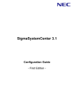
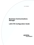
BCM and UPS power and control connections
The UPS device operates in parallel with the BCM 200/400. The Business Communications
Manager obtains power through the UPS. The UPS obtains power from a conventional AC power
source.
The UPS meets Business Communications Manager power delivery requirements for 110~120 and
220~240 Volt standards. The BCM’s operational power usage range (shown in the table below) is
compatible with the UPS’ operating range.
BCM Input Power Source
110 ~ 120 Volt power standards
220 ~ 240 Volt power standards
Minimum (VAC)
Maximum (VAC)
Minimum (VAC)
Maximum (VAC)
90.0
130.0
220.0
265.0
The serial connection between the BCM and UPS provides power monitoring and control
capability. The UPS service uses standard RS232 serial protocol. Figure 2 on page 18 shows the
physical BCM connections and OAM topology.
Figure 2 UPS / BCM power connections and topology
Unified Manager
Workstation provides UPS
configuration, service
activation and OAM
monitoring applications
Local Area
Network
CTM 4
1
Aux
2
3
4
UPS device
DSM 16+
1
2
3
4
1
2
3
4
Plug BCM power
cord into UPS
Power
Status
COM port supports a DB9 serial connection
to a UPS for power monitoring
P0607274 01
Plug UPS into AC
power source
Chapter 1 Uninterruptable Power Supply (UPS) Overview
19
UPS threshold values
UPS threshold values are tolerances that define the UPS operational requirements and power
delivery capability. The UPS reports the threshold values through the Unified Manager. The
following table provides the minimum and maximum UPS threshold values for 110~120 and
220~240 Volt standards. All configuration data is stored in the F:\Program
Files\PwerChute\PwrChute.ini file.
110 ~ 120 Volt UPS Threshold Values
220 ~ 240 Volt UPS Threshold Values
Minimum
Maximum
Minimum
Maximum
1
90
120
208
253
Line voltage maximum (AC)
90
120
208
253
UPS output voltage (AC)
106
127
220
240
Battery voltage (DC)
16
36
16
36
Output frequency (Hz)
59
60.25
49
50.25
UPS load (%)
0
125
0
125
-15
45
-15
45
Line voltage minimum (AC)
3
4
5
6
Temperature (degr. C)
7
2
1 Line voltage minimum: The lowest AC input voltage supplied by the power source. This threshold represents the
value recorded since you started the user interface module.
2. Line voltage maximum: The highest AC input voltage supplied by the power source. This threshold represents the
value recorded since you started the user interface module.
3. UPS Output voltage: The voltage (AC) supplied by the UPS to the equipment supported.
4. Battery voltage: The voltage (DC) supplied by the UPS to the equipment supported during a power outage.
5. Output frequency: The line voltage frequency.
6. UPS load: The amount of battery power drawn by the equipment supported during a recorded interval. The value
is represented by the percentage of the total power available in the UPS.
7. Temperature: The internal temperature of the UPS device.
Alarm and event reporting
The BCM software monitors the UPS threshold values and provides event reporting capability to
the BCM SNMP trap and alarm reporting systems. The BCM monitors the UPS through the COM
port and polls the UPS every 60 seconds. Power supply failure notification is sent to the OAM and
alarm subsystem and to the recovery application.
The threshold values relate to the following:
•
•
Power: Utility power failure, low battery power for the UPS device. The message advises
users to take appropriate action on their BCM. The battery must be recharged for every minute
of run time. Appropriate action is to verify the power supply is functional. Alternatively, try to
connect to a secondary power supply, possibly switch telephony/data services to alternate
location if possible.
Communications: Send a message when communication with the UPS starts. Send a message
when communication with the UPS is lost (e.g. remote UPS shutdown). If communication loss
occurs, verify serial connection is functional or UPS is operational.
UPS Installation and Configuration Guide
20
Chapter 1 Uninterruptable Power Supply (UPS) Overview
•
Operating conditions: send a message when internal UPS operating temperature falls outside
of the upper or lower threshold.
See Table 1 on page 20 for further information on event messages.
Table 1 UPS Event messages
Event ID Event
Type
Event ID Event
Type
1005
Administrative shutdown
Info
1002
Communication Established
Info
100500
Administrative shutdown started
Info
300400
Communication lost while on
battery
Info
100501
Administrative shutdown: User
initiated
Info
300000
Unable to communicate with UPS
Warn
100502
Administrative shutdown: Weekly
shutdown
Info
300200
UPS self-test failed
Error
100503
Administrative shutdown: Daily
shutdown
Info
100700
UPS returned from low battery
condition
Info
110000
Ambient temperature back within
thresholds
Info
100900
UPS batteries no longer need
replacing
Info
110100
Ambient humidity back within
thresholds
Info
101300
UPS overload condition solved
Info
301400
Base module fan needs repair
Error
101400
UPS runtime calibration initiated
Info
301500
Base module bypass power supply Error
needs repair
101500
UPS runtime calibration completed
Info
310001
Below lower ambient temperature
threshold
Warn
1004
UPS self-test passed
Info
310101
Below humidity threshold
Warn
101700
UPS returned from bypass
Info
2037
Bypass contactor failed
Error
1102
UPS internal temperature in
bounds
Info
1040
Bypass contactor OK
Info
200000
UPS on battery
Info
1033
Battery added
Info
200001
UPS on battery: High input line
voltage
Warn
1034
Battery removed
Info
200002
UPS on battery: Brownout
Warn
301000
Check installation of Smart Cell
signal cable
Warn
200003
UPS on battery: Blackout
Warn
310002
Exceeded upper ambient
temperature threshold
Warn
200004
UPS on battery: Small momentary
sag
Warn
310102
Exceeded upper humidity threshold Warn
200006
UPS on battery: Deep momentary
sag
Warn
203800
Input circuit breaker tripped
Info
200005
UPS on battery: Small momentary
spike
Warn
203900
Input circuit breaker reset
Info
200008
UPS on battery: Simulated power
failure
Warn
200301
Low battery condition
Warn
103100
UPS module added
Info
103500
Main Intelligence module OK
Info
103200
UPS module removed
Info
103600
Main Intelligence module added
Info
200200
UPS enabling SmartBoost
Info
P0607274 01
Chapter 1 Uninterruptable Power Supply (UPS) Overview
21
Table 1 UPS Event messages
Event ID Event
Type
Event ID Event
Type
203200
Main intelligence module removed
Warn
200400
UPS runtime calibration cancelled
Info
203300
Main intelligence module failed
Error
200401
UPS runtime calibration cancelled
by user
Info
1030
Minimum redundancy regained
Warn
200402
UPS runtime calibration aborted by Info
power failure
310700
Maximum internal UPS
temperature exceeded
Warn
200403
UPS unable to perform runtime
calibration: Capacity < 100 %
Warn
2030
Minimum redundancy lost
Warn
200700
UPS enabling SmartTrim
Info
100300
Normal power restored: UPS on
line
Info
201301
UPS on bypass: user set via
software or panel
Info
103700
Redundant intelligence module OK Info
201302
UPS system is in maintenance
bypass set by switch
Info
103800
Redundant intelligence module
added
Info
203100
UPS module failed
Error
203400
Redundant intelligence module
removed
Warn
301300
UPS internal temperature over limit Warn
203500
Redundant intelligence module
failed
Warn
301301
UPS battery charger failure
Warn
203600
System level fan OK
Info
200007
UPS on battery: Large momentary
spike
Warn
2001
System shutdown Complete
Info
301302
UPS on bypass: severe DC
imbalance overload
Warn
2036
System level fan failed
Error
301303
UPS on bypass: output voltage
outside limits
Warn
1006
Shutdown cancelled
Info
301304
UPS on bypass: top module fan
needs repair
Error
1016
System Shutdown started
Info
300100
UPS output overload
Warn
100401
Scheduled UPS self-test passed
Info
300300
UPS battery is discharged
Warn
300201
Scheduled UPS self-test failed
Error
301600
UPS battery needs replacing
Error
300202
Scheduled UPS self-test failed:
Invalid test
Warn
100402
User-initiated UPS self-test passed Info
100403
Self-test at UPS passed
Info
100601
User-initiated shutdown cancelled
Info
300205
Self-test at UPS failed
Error
101601
User-initiated shutdown started
Info
300206
Self-test at UPS failed: Invalid test
Warn
300204
User-initiated self-test failed
Error
1018
Smart Cell signal restored
Info
300206
User-initiated self-test failed: Invalid Warn
test
UPS Installation and Configuration Guide
22
Chapter 1 Uninterruptable Power Supply (UPS) Overview
Operational measurements and accounting
The Business Communications Manager collects operational measurement (OM) information
from the UPS and saves the data in a log file. The OM information is viewed through the Unified
Manager or archlog applications. The OM values can be reset using the Unified Manager. For
further information on how to access logs using the Unified Manager, refer to the Management
User Guide.
Log files and traces
The BCM UPS service logs into (APC PowerChute.log) to track internal and external UPS service
functionality. The messages described in Table 1 on page 20 are captured in the log file which can
be viewed through the Unified Manager.
1
Event Log Location (“F:\Program Files\PwerChute\PwrChute.log”, Fixed), this file checked
periodically by Unified Manager collecting OMs information and UPS overall status.
2
Data Log Location (“F:\Program Files\PwerChute\PwrChute.dat”, Fixed), this file checked
periodically by Unified Manager collecting UPS Status Monitor information.
3
Error Log Location (“F:\Program Files\PwerChute\PwrChute.err”, Fixed), this file checked
periodically by Unified Manager collecting the UPS failures.
UPS default configuration settings
The UPS software is configured under the default settings defined in Table 2 on page 22.
Table 2 UPS default settings
General
Signalling Type
Smart
Port
COM1
Auto UPS Reboot Enabled
Yes
Cable Type
Normal
Event Logging
Event Log Enabled
Yes
Event Log Location
“F:\Program Files\PwerChute\PwrChute.log”
Select the Event Log Maximum
5000 KB
Data Logging
Data Log Enabled
Yes
Data Log Location
“F:\Program Files\PwerChute\PwrChute.dat”
Select the Data Log Maximum
5000 KB
Data Logging interval
60 Seconds
Error Logging
P0607274 01
Chapter 1 Uninterruptable Power Supply (UPS) Overview
23
Table 2 UPS default settings
Error Log Enabled
Yes
Error Log Location
“F:\Program Files\PwerChute\PwrChute.err”
Select the Error Log Maximum
5000 KB.
Shutdown
Shutdown Delay
30 Seconds
Admin Shutdown Delay
30 Seconds
UPS Installation and Configuration Guide
24
Chapter 1 Uninterruptable Power Supply (UPS) Overview
P0607274 01
25
Chapter 2
Install and Initialize the Uninterruptable Power Supply
This section describes how to install and initialize the Uninterruptable power supply (UPS) on the
Business Communications Manager (BCM) 200, 400 and 1000 models.
This section describes the following:
Procedure: Install the UPS on page 25
Procedure: Initialize the serial port on page 26
Procedure: Enable UPSConsoleToggle: on page 27
Procedure: Enable the console (batch file): on page 28
Install and initialize the UPS
Use the procedure in this section to perform a first-time UPS installation on your Business
Communications Manager.
Procedure: Install the UPS
Use this procedure to install and power-up the Business Communications Manager through the
UPS. Refer also to the UPS product installation manual for detailed instructions.
To install the Business Communications Manager to the UPS:
1
Plug the UPS power cord into the AC power source (wall outlet).
2
Plug the BCM power cord into the UPS.
3
Connect the serial cable from the Business Communications Manager to the UPS.
4
Ensure you have a LAN connection from the Business Communications Manager to the
Unified Manager workstation.
5
Power-up the UPS.
6
Power-up the Business Communications Manager.
7
Wait for the Business Communications Manager to finish boot-up.
8
This procedure is complete.
UPS Installation and Configuration Guide
26
Chapter 2 Install and Initialize the Uninterruptable Power Supply
Procedure: Initialize the serial port
The Unified Manager provides a means to modify the serial port configuration and UPS service
settings. When you enable the UPS device using the Unified Manager interface, Unified Manager
turns the console service OFF and turns the UPS service ON. Conversely, if the UPS serial cable is
disconnected, the BCM Unified Manager turns the console service ON and turns the UPS service
OFF.
To initialize the UPS serial port:
1
Connect the serial cable from the BCM to the UPS.
2
Access the correct Business Communications Manager in your network from the Unified
Manager workstation browser.
3
Select the Services key from the Unified Manager main page and expand the navigation tree.
A list of available services appears in the Services information frame.
4
Select the UPS heading from the navigation tree window.
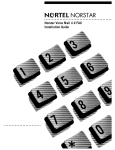
5
Select the UPS configuration tab from the UPS setup screen. The UPS configuration setup
screen appears (see Figure 3 on page 26).
Figure 3 UPS configuration setup screen display
6
Select the UPS radio button to enable the serial port for use by the UPS.
P0607274 01
Chapter 2 Install and Initialize the Uninterruptable Power Supply
7
27
Select the power source type (110 ~ 120v or 220 ~ 240v).
Note: Once the UPS is selected and enabled on the Unified Manager “Serial Selection
Page”, the UPS sends the message “UPS Communication Established” to the NT event
log, when the UPS communication started. If the BCM loses or cannot establish a link to
the UPS, an error log appears “Unable to Communicate with the UPS”.
8
This procedure is complete.
UPSConsoleToggle Service
UPSConsoleToggle is an Auto-Start service that initiates at system boot time to enable the serial
console for 15 minutes. Plug the console serial cable into the BCM and work on BCM console for
a period of 15 minutes.
After 15 minutes, the service switches back to the UPS to enable the UPS (if the UPS was
originally selected and enabled).
•
•
To extend the Console time, stop the UPSConsoleToggle using the command “Net Stop
UPSConsoleToggle”.
The UPS service needs to be enabled from the Unified Manager when the user ends the
console session.
Procedure: Enable UPSConsoleToggle:
Use this procedure to enable the UPSConsoleToggle service.
To enable the UPSConsoleToggle service:
1
Wait for all services to be up and running.
2
Verify that the UPS service is running.
3
If UPS service is running, change its start-up type to Manual-Start and the console CMDRMT
service to Auto-Start, then stop UPS service and start Console service.
4
Wait for 15 minutes.
5
Toggle the UPS/Console.
Change the console start-up type to Manual-Start and the UPS to Auto-Start. This stops the
console service and starts the UPS service.
6
Stop the UPSConsoleToggle service.
UPS Installation and Configuration Guide
28
Chapter 2 Install and Initialize the Uninterruptable Power Supply
Procedure: Enable the console (batch file):
Use this procedure to use the serial port for startup or emergency maintenance purposes.
1
If you have access to the Unified Manager, from Services/UPS, select the console.
2
If you have an access to the BCM via the IP, Telnet to the BCM using the IP connection and
run the batch file called “EnableConsole.bat” located on “F:\Program Files\Nortel
Networks\Voice Platform”.
3
Running EnableConsole.bat will do the following:
•
•
•
4
Changes the value of the register key to:
“KEY_LOCAL_MACHINE\SOFTWARE\APC\GUI\SerialSelect” to 0
Stops the UPS service and changes its startup type to Manual.
Changes the CMDRMT (Console Service) startup type to AUTOMATIC and start it.
This procedure is complete.
P0607274 01
29
Chapter 3
Monitor the Uninterruptable Power Supply
This section describes how to monitor the Uninterruptable power supply (UPS) on the Business
Communications Manager (BCM) 200, 400 and 1000 models.
This section describes the following procedures:
Procedure: Access the UPS Status monitor on page 30
Procedure: Access the UPS OM and log reports on page 31
Procedure: Access the UPS status report on page 33
Procedure: Test the UPS on page 34
Monitor the UPS
The Business Communications Manager UPS service communicates with the UPS device through
a serial (DB9) cable. The UPS service provides the following capabilities:
•
•
•
•
•
•
•
•
Monitors the UPS using the COM port. The BCM polls the UPS device every 60 seconds.
Power source failure notification is sent to the OAM and alarm subsystem and to the recovery
application.
Provides a warning signal when UPS battery power is low.
Allows you to perform a remote UPS shutdown.
Allows you to configure battery recharge time. The battery must recharge for every minute of
run time.
Allows you to configure the delay between warning messages.
Allows an auto power off for the Business Communications Manager.
Allows you to configures the UPS to perform a graceful BCM shutdown (and cleanly
shutdown telephony) two minutes before the battery is drained.
There are two methods to monitor the UPS:
1
Select the UPS Status monitor tab to monitor the UPS device only (see “Procedure: Access the
UPS Status monitor” on page 30)
2
Select the UPS Status report to monitor the UPS device and BCM UPS service (see
“Procedure: Access the UPS status report” on page 33).
UPS Installation and Configuration Guide
30
Chapter 3 Monitor the Uninterruptable Power Supply
Procedure: Access the UPS Status monitor
Use this procedure to access the UPS status monitor tab interface and monitor the UPS device.
To access the UPS status monitor:
1
Initialize the serial port as described in Procedure: Initialize the serial port on page 26.
2
Access the correct Business Communications Manager in your network from the Unified
Manager workstation browser.
3
Select the Services key from the Unified Manager main page and expand the navigation tree.
A list of available services appears in the Services information frame.
4
Select the UPS heading from the navigation tree window.
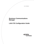
5
Select the UPS status monitor tab from the UPS setup screen. The UPS status monitor screen
appears (see Figure 4 on page 30).
Figure 4 UPS Status monitor screen display
6
Examine the UPS device status information displayed in the information window.
7
This procedure is complete.
P0607274 01
Chapter 3 Monitor the Uninterruptable Power Supply
31
Procedure: Access the UPS OM and log reports
Use this procedure to access the UPS operational metrics (OMs), UPS log files or status reports.
To access the UPS OM or Log reports:
1
Initialize the serial port as described in Procedure: Initialize the serial port on page 26.
2
Access the correct Business Communications Manager in your network from the Unified
Manager workstation browser.
3
Select the Services key from the Unified Manager main page and expand the navigation tree.
A list of available services appears in the Services information frame.
4
Select the UPS heading from the navigation tree window.
5
Select the Report from the top line menu.
6
Select the OMs Report from the drop-down menu. The UPS OMs report appears (see Figure 5
on page 31).
Figure 5 UPS OMs report
UPS Installation and Configuration Guide
32
Chapter 3 Monitor the Uninterruptable Power Supply
7
To reset the OMs, select “Click here to reset the oms values” from the screen.
8
To view the Log files, select “Click here to view UPS Log File” from the screen (see Figure
6 on page 32).
Figure 6 UPS Log file report
9
To print the report, select “Print this Report” from the screen.
10 To close the report window, select “Close This Window” from the screen.
11 This procedure is complete.
P0607274 01
Chapter 3 Monitor the Uninterruptable Power Supply
33
Procedure: Access the UPS status report
Use this procedure to access the UPS status report to monitor the UPS device and BCM UPS
service.
To access the UPS status report:
1
Initialize the serial port as described in Procedure: Initialize the serial port on page 26.
2
Access the correct Business Communications Manager in your network from the Unified
Manager workstation browser.
3
Select the Services key from the Unified Manager main page and expand the navigation tree.
A list of available services appears in the Services information frame.
4
Select the UPS heading from the navigation tree window.
5
Select the Report from the top line menu.
6
Select the UPS Status report from the drop-down menu. The UPS status report appears (see
Figure 7 on page 33).
Figure 7 UPS status report
7
To print the report, select “Print this Report” from the screen.
UPS Installation and Configuration Guide
34
Chapter 3 Monitor the Uninterruptable Power Supply
8
To close the report window, select “Close This Window” from the screen.
9
This procedure is complete.
Procedure: Test the UPS
Use this procedure to test the UPS power backup function after you have installed and configured
the UPS for the Business Communications Manager.
The UPS device automatically performs a biweekly self-test. Locate the test results under the
following path:
F:\Program Files\PwerChute\PwrChute.log file.
The APC PwrChute Plus software is recommended to simulate and test the UPS self test and UPS
calibration. (APC PwrChute Plus software already installed on BCM).
To test the UPS:
1
Ensure that the serial cable between the Business Communications Manager and the UPS (or
the expansion chassis) is securely connected at both ends.
2
Simulate a power failure. Disconnect the power cord from the AC power source (wall outlet)
to the UPS device.
3
Verify that the BCM connected to the UPS device remains operational
4
Verify that a warning message and/or alert appears on the client screen.
5
Wait until the UPS battery reaches a low level. A system shutdown should occur (on the BCM
200/400 and 1000).
6
After system shutdown, restore power to the UPS device.
7
Check the system log in the Event Viewer to ensure that all actions are logged and that there
are no errors.
8
This procedure is complete.
P0607274 01