1
Nortel Business Ethernet Switch 1000 Series
Using The Nortel Business
Ethernet Switch 1000 Series
ATTENTION
Clicking on a PDF hyperlink takes you to the appropriate page. If necessary,
scroll up or down the page to see the beginning of the referenced section.
NN47927-300
.
Document status: Standard
Document version: 01.01
Document date: 10 January 2007
Copyright © 2007, Nortel Networks
All Rights Reserved.
Sourced in Canada and the United States of America.
The information in this document is subject to change without notice. The statements, configurations, technical
data, and recommendations in this document are believed to be accurate and reliable, but are presented without
express or implied warranty. Users must take full responsibility for their applications of any products specified in this
document. The information in this document is proprietary to Nortel Networks.
The software described in this document is furnished under a license agreement and may be used only in accordance
with the terms of that license. The software license agreement is included in this document.
Trademarks
Nortel, Nortel Networks, the Nortel logo, and the Globemark are trademarks of Nortel Networks.
The asterisk after a name denotes a trademarked item.
Restricted rights legend
Use, duplication, or disclosure by the United States Government is subject to restrictions as set forth in subparagraph
(c)(1)(ii) of the Rights in Technical Data and Computer Software clause at DFARS 252.227-7013.
Notwithstanding any other license agreement that may pertain to, or accompany the delivery of, this computer
software, the rights of the United States Government regarding its use, reproduction, and disclosure are as set forth
in the Commercial Computer Software-Restricted Rights clause at FAR 52.227-19.
Statement of conditions
In the interest of improving internal design, operational function, and/or reliability, Nortel Networks reserves the right
to make changes to the products described in this document without notice.
Nortel Networks does not assume any liability that may occur due to the use or application of the product(s) or
circuit layout(s) described herein.
Portions of the code in this software product may be Copyright © 1988, Regents of the University of California. All
rights reserved. Redistribution and use in source and binary forms of such portions are permitted, provided that the
above copyright notice and this paragraph are duplicated in all such forms and that any documentation, advertising
materials, and other materials related to such distribution and use acknowledge that such portions of the software
were developed by the University of California, Berkeley. The name of the University may not be used to endorse or
promote products derived from such portions of the software without specific prior written permission.
SUCH PORTIONS OF THE SOFTWARE ARE PROVIDED “AS IS” AND WITHOUT ANY EXPRESS OR IMPLIED
WARRANTIES, INCLUDING, WITHOUT LIMITATION, THE IMPLIED WARRANTIES OF MERCHANTABILITY AND
FITNESS FOR A PARTICULAR PURPOSE.
In addition, the program and information contained herein are licensed only pursuant to a license agreement that
contains restrictions on use and disclosure (that may incorporate by reference certain limitations and notices
imposed by third parties).
Nortel Networks software license agreement
This Software License Agreement (“License Agreement”) is between you, the end-user (“Customer”) and Nortel
Networks Corporation and its subsidiaries and affiliates (“Nortel Networks”). PLEASE READ THE FOLLOWING
CAREFULLY. YOU MUST ACCEPT THESE LICENSE TERMS IN ORDER TO DOWNLOAD AND/OR USE THE
SOFTWARE. USE OF THE SOFTWARE CONSTITUTES YOUR ACCEPTANCE OF THIS LICENSE AGREEMENT.
If you do not accept these terms and conditions, return the Software, unused and in the original shipping container,
within 30 days of purchase to obtain a credit for the full purchase price.
“Software” is owned or licensed by Nortel Networks, its parent or one of its subsidiaries or affiliates, and is
copyrighted and licensed, not sold. Software consists of machine-readable instructions, its components, data,
audio-visual content (such as images, text, recordings or pictures) and related licensed materials including all whole
or partial copies. Nortel Networks grants you a license to use the Software only in the country where you acquired the
Software. You obtain no rights other than those granted to you under this License Agreement. You are responsible for
the selection of the Software and for the installation of, use of, and results obtained from the Software.
1.
Licensed Use of Software. Nortel Networks grants Customer a nonexclusive license to use a copy of the
Software on only one machine at any one time or to the extent of the activation or authorized usage level,
whichever is applicable. To the extent Software is furnished for use with designated hardware or Customer
furnished equipment (“CFE”), Customer is granted a nonexclusive license to use Software only on such
hardware or CFE, as applicable. Software contains trade secrets and Customer agrees to treat Software as
confidential information using the same care and discretion Customer uses with its own similar information that it
does not wish to disclose, publish or disseminate. Customer will ensure that anyone who uses the Software
does so only in compliance with the terms of this Agreement. Customer shall not a) use, copy, modify, transfer or
distribute the Software except as expressly authorized; b) reverse assemble, reverse compile, reverse engineer
or otherwise translate the Software; c) create derivative works or modifications unless expressly authorized; or d)
sublicense, rent or lease the Software. Licensors of intellectual property to Nortel Networks are beneficiaries of
this provision. Upon termination or breach of the license by Customer or in the event designated hardware or
CFE is no longer in use, Customer will promptly return the Software to Nortel Networks or certify its destruction.
Nortel Networks may audit by remote polling or other reasonable means to determine Customer’s Software
activation or usage levels. If suppliers of third party software included in Software require Nortel Networks to
include additional or different terms, Customer agrees to abide by such terms provided by Nortel Networks
with respect to such third party software.
2.
Warranty. Except as may be otherwise expressly agreed to in writing between Nortel Networks and Customer,
Software is provided “AS IS” without any warranties (conditions) of any kind. NORTEL NETWORKS DISCLAIMS
ALL WARRANTIES (CONDITIONS) FOR THE SOFTWARE, EITHER EXPRESS OR IMPLIED, INCLUDING,
BUT NOT LIMITED TO THE IMPLIED WARRANTIES OF MERCHANTABILITY AND FITNESS FOR A
PARTICULAR PURPOSE AND ANY WARRANTY OF NON-INFRINGEMENT. Nortel Networks is not obligated
to provide support of any kind for the Software. Some jurisdictions do not allow exclusion of implied warranties,
and, in such event, the above exclusions may not apply.
3.
Limitation of Remedies. IN NO EVENT SHALL NORTEL NETWORKS OR ITS AGENTS OR SUPPLIERS BE
LIABLE FOR ANY OF THE FOLLOWING: a) DAMAGES BASED ON ANY THIRD PARTY CLAIM; b) LOSS
OF, OR DAMAGE TO, CUSTOMER’S RECORDS, FILES OR DATA; OR c) DIRECT, INDIRECT, SPECIAL,
INCIDENTAL, PUNITIVE, OR CONSEQUENTIAL DAMAGES (INCLUDING LOST PROFITS OR SAVINGS),
WHETHER IN CONTRACT, TORT OR OTHERWISE (INCLUDING NEGLIGENCE) ARISING OUT OF YOUR
USE OF THE SOFTWARE, EVEN IF NORTEL NETWORKS, ITS AGENTS OR SUPPLIERS HAVE BEEN
ADVISED OF THEIR POSSIBILITY. The foregoing limitations of remedies also apply to any developer and/or
supplier of the Software. Such developer and/or supplier is an intended beneficiary of this Section. Some
jurisdictions do not allow these limitations or exclusions and, in such event, they may not apply.
4.
General
a.
If Customer is the United States Government, the following paragraph shall apply: All Nortel Networks
Software available under this License Agreement is commercial computer software and commercial
computer software documentation and, in the event Software is licensed for or on behalf of the United States
Government, the respective rights to the software and software documentation are governed by Nortel
Networks standard commercial license in accordance with U.S. Federal Regulations at 48 C.F.R. Sections
12.212 (for non-DoD entities) and 48 C.F.R. 227.7202 (for DoD entities).
b.
Customer may terminate the license at any time. Nortel Networks may terminate the license if Customer
fails to comply with the terms and conditions of this license. In either event, upon termination, Customer
must either return the Software to Nortel Networks or certify its destruction.
c.
Customer is responsible for payment of any taxes, including personal property taxes, resulting from
Customer’s use of the Software. Customer agrees to comply with all applicable laws including all applicable
export and import laws and regulations.
d.
Neither party may bring an action, regardless of form, more than two years after the cause of the action
arose.
e.
The terms and conditions of this License Agreement form the complete and exclusive agreement between
Customer and Nortel Networks.
f.
This License Agreement is governed by the laws of the country in which Customer acquires the Software.
If the Software is acquired in the United States, then this License Agreement is governed by the laws of
the state of New York.
5
Contents
Preface
13
Before you begin 13
Text conventions 14
Related publications 15
How to get help 15
New in this release
17
Features 17
Release 1.0 17
Release 1.1 17
Introduction
19
Using the Web-based user interface
21
Prerequisites for using the Web-based user interface 21
Setting up the Web-based user interface 22
Logging on to the Web-based management interface 23
Logging off from the Web-based management interface 23
Navigating the Web-based user interface 24
Menu and management pages 25
Configuration options 26
Setting the IP address 26
Setting the IP address automatically 27
Changing the administrator password 29
Configuring Web security 29
Configuring RADIUS security 30
Configuring console security 31
Configuring system information 32
Help screens 33
Accessing BES1000 help 33
Accessing BES1000 release notes 33
Accessing BES1000 manuals 34
Accessing the management interface 34
Nortel Business Ethernet Switch 1000 Series
Using The Nortel Business Ethernet Switch 1000 Series
NN47927-300 01.01 Standard
1.1 10 January 2007
Copyright © 2007, Nortel Networks
.
Nortel Networks Confidential
6 Contents
BES1000 basic configuration using the Web-based user
interface
37
Configuring initial settings by using the Quick Start feature 37
Configuring Simple Network Management Protocol (SNMP) 39
Configuring an SNMP trap receiver 39
Deleting an SNMP trap receiver configuration 40
Configuring SNMPv3 management access 41
Viewing SNMPv3 System information 41
Configuring SNMPv3 users 42
Configuring group membership 43
Configuring group access rights 44
Setting SNMPv3 views 45
Configuring notification messages 46
Configuring Target Address 46
Configuring target parameters 47
Configuring Virtual LANs (VLANs) 48
Creating a port-based VLAN 48
Configuring a port-based VLAN 49
Modifying a port-based VLAN 50
Selecting a management VLAN 50
Deleting a VLAN configuration 51
Configuring Link Aggregation Control Protocol (LACP) ports 52
Configuring Power over Ethernet (PoE) management 52
Configuring port PoE power priorities 53
Viewing Spanning Tree Port information 54
Viewing Spanning Tree Bridge information 55
Configuring rate limiting 56
BES1000 advanced features configuration using the Web-based
interface
59
Configuring switch security 60
Configuring port authentication 60
Configuring Web security 61
Configuring console security 62
Configuring RADIUS security 63
Configuring Internet Group Management Protocol (IGMP) snooping
Configuring flow control 64
Configuring console port communication speed 64
Configuring port management properties 65
Configuring Quality of Service (QoS) settings 66
Displaying the QoS interface configuration 66
Configuring 802.1p priority settings 67
Enabling Differentiated Services Code Point (DSCP) mapping 68
63
Nortel Business Ethernet Switch 1000 Series
Using The Nortel Business Ethernet Switch 1000 Series
NN47927-300 01.01 Standard
1.1 10 January 2007
Copyright © 2007, Nortel Networks
.
Nortel Networks Confidential
Contents 7
Displaying DSCP queue assignment 69
Enabling DSCP mapping 70
Configuring MAC address learning 70
Configuring MAC address-based security 71
Configuring port lists 72
Finding MAC address tables 72
Adding MAC addresses 73
Deleting MAC DAs 74
Enabling security on ports 74
Filtering MAC destination addresses 75
Filtering MAC Multicast addresses 76
Configuring Link Layer Discovery Protocol (LLDP) transmission properties
Configuring LLDP port status 78
Configuring LLDP Tx - TLV transmit status 79
Configuring remote access 80
Configuring Simple Network Time Protocol (SNTP) 81
77
Using the Element Manager
85
Connecting to a BES1000 Series switch using the Element Manager
Working with configuration files 86
Configuring EAPOL security 88
85
BES1000 basic configuration using Element Manager
89
Navigation 89
Configuring initial settings using the Quick Start feature 89
Setting the Element Manager Simple Network Management Protocol (SNMP)
properties 91
Configuring SNMP Trap Receivers 92
Deleting a Trap Receivers entry 93
Adding items to the Security List 94
Deleting a Security List entry 95
Configuring ports 95
Viewing and editing port configurations 95
Interface tab 96
PoE tab 97
EAPOL tab 97
Configuring LLDP 98
802.1ab - Globals tab 98
802.1ab - Port tab 100
802.1ab - TX Stats tab 101
802.1ab - RX Stats tab 101
802.1ab - Local System tab 102
802.1ab - Local Port tab 103
802.1ab - Local Management tab 103
802.1ab - Neighbor tab 104
Nortel Business Ethernet Switch 1000 Series
Using The Nortel Business Ethernet Switch 1000 Series
NN47927-300 01.01 Standard
1.1 10 January 2007
Copyright © 2007, Nortel Networks
.
Nortel Networks Confidential
8 Contents
802.1ab - Neighbor Mgmt Address tab 105
Configuring rate limiting 105
Creating a port-based VLAN 106
Modifying a VLAN 107
Deleting a VLAN 107
Configuring Link Aggregation Control Protocol (LACP) ports
108
BES1000 advanced features configuration using Element
Manager
Configuring Simple Network Time Protocol (SNTP) 111
Configuring Internet Group Management Protocol (IGMP) snooping
Enabling Multicast filtering 113
Configuring MAC address learning 114
Filtering MAC multicast addresses 114
Deleting a MAC Multicast address 115
Configuring Quality of Service (QoS) 115
111
113
BES1000 administration
121
Changing a PC IP address 121
System Administration using the Web-based user interface 122
Using the virtual cable tester 123
Running a copper cable extended test 124
Viewing Link Aggregation Control Protocol (LACP) Bridge configuration
Viewing LACP port statistics 126
Displaying multicast group membership 127
Viewing the system log 128
Viewing statistics 129
Viewing VLAN port information 136
RMON Fault threshold page 137
Viewing the RMON fault event log 137
Viewing RMON Ethernet statistics 138
Viewing RMON history 139
Viewing LLDP local system data 140
Displaying LLDP Neighbor properties 142
Displaying LLDP Neighbor Management properties 143
Displaying LLDP statistics 144
System Administration using the Element Manager 145
Configuring the Virtual Cable Tester 146
Viewing VCT test results 146
Viewing switch power information 147
Viewing device properties 148
Viewing the trap log 151
Viewing switch IP information 152
Viewing VLAN properties 153
Viewing learned MAC addresses by VLAN 155
125
Nortel Business Ethernet Switch 1000 Series
Using The Nortel Business Ethernet Switch 1000 Series
NN47927-300 01.01 Standard
1.1 10 January 2007
Copyright © 2007, Nortel Networks
.
Nortel Networks Confidential
Contents 9
Viewing Unit information 156
Displaying STP properties 157
Displaying LACP 159
Viewing Security settings 160
Viewing statistics 163
Viewing RMON history statistics 176
Viewing RMON Events 178
RMON Ether Stats tab for graphing ports 179
Configuring RMON 182
Configuring RMON history 183
Enabling Ethernet statistics gathering 185
Configuring RMON alarms 186
Creating an alarm 187
Deleting an alarm 188
Configuring RMON events 189
How events work 189
Creating an RMON Event 189
Deleting an RMON Event 190
Disabling RMON history statistics 190
Viewing Alarm settings 191
Disabling Ethernet statistics gathering 195
Fault management 195
Interpreting the LEDs 196
Diagnosing and correcting problems 196
Port connection problems 198
Creating an RMON fault threshold 199
Deleting an RMON threshold configuration 200
Viewing RMON history 200
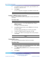
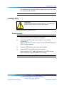
Installing SFPs 201
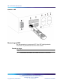
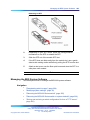
Removing an SFP 202
Managing the BES System Software 203
Downloading switch images 204
Rebooting the BES1000 Series switch 205
Rebooting the BES1000 Series switch to system defaults 206
Storing and retrieving a switch configuration file from a TFTP server
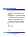
BES1000 fundamentals
206
209
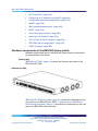
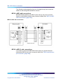
Hardware components of the BES1000 Series switch 210
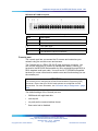
Front panel 210
Console port 211
Reset button - for reset to factory default 212
SFP gigabit interface converters 212
10, 100, and 1000 RJ-45 port connectors 212
Auto-MDI and MDI-X 213
Nortel Business Ethernet Switch 1000 Series
Using The Nortel Business Ethernet Switch 1000 Series
NN47927-300 01.01 Standard
1.1 10 January 2007
Copyright © 2007, Nortel Networks
.
Nortel Networks Confidential
10 Contents
Power over Ethernet on BES1020 213
LED display panel 213
Back panel 214
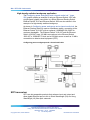
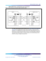
Network configuration examples 218
Desktop switch application 218
Segment switch application 219
High-density switched workgroup application 220
SFP transceiver 220
Guidelines 221
Product description 222
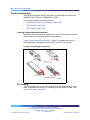
Locking and extractor mechanisms 222
SFP labeling 222
SFP models 223
Configuration and switch management 223
Configuring an IP address using BootP 224
BootP Configuration Requirements 224
BootP configuration Parameters 224
BootP or Default IP 225
BootP Always 225
BootP Disabled 225
BootP or Last Address 226
Troubleshooting 226
Flash memory storage 226
Switch software image storage 226
Autosensing and autonegotiation 227
RFCs 227
Standards 227
EAPOL and RADIUS security 228
SNMP 228
MAC address-based security 228
SNTP 229
Virtual local area networks 229
Port-based VLANs 230
VLAN support 230
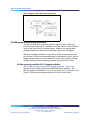
IEEE 802.1Q VLAN workgroups 231
VLAN workgroup example 231
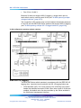
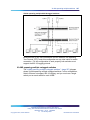
IEEE 802.1Q tagging 232
VLANs spanning multiple switches 236
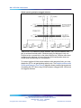
VLANs spanning multiple 802.1Q tagged switches 236
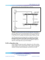
VLANS spanning multiple untagged switches 237
VLAN configuration rules 239
Spanning Tree Protocol 240
Spanning Tree Protocol - IEEE 802.1D 240
Nortel Business Ethernet Switch 1000 Series
Using The Nortel Business Ethernet Switch 1000 Series
NN47927-300 01.01 Standard
1.1 10 January 2007
Copyright © 2007, Nortel Networks
.
Nortel Networks Confidential
Contents 11
Port states 240
Aging of Dynamic Entries in Forwarding Database
Port path cost 241
Rapid Spanning Tree Protocol - IEEE 802.1w 242
Interoperability with legacy STP 242
Rapid convergent 244
Negotiation process 244
802.1p Class of Service support 246
802.1p COS Remarking 247
IEEE 802.3ad Link Aggregation 247
Link aggregation rules 248
IGMP Snooping 249
Configuring IP and gateway settings 249
241
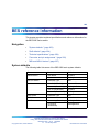
BES reference information
253
System defaults 253
QoS defaults 254
Technical specifications 254
SFP physical specifications 254
Specifications for LC type 1000BASE-SX connectivity 254
Specifications for LC type 1000BASE-LX connectivity 255
Specifications for MT-RJ Type 1000BASE-SX connectivity 256
Connector and pin assignments 256
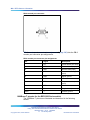
RJ-45 (10BASE-T/100BASE-TX) port connectors 257
MDI and MDI-X devices 257
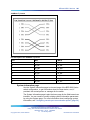
MDI-X to MDI cable connections 258
MDI-X to MDI-X cable connections 258
DB-9 (RS-232-D) console/comm port connector 259
1000Base-T pinouts for the BES1000 Series switch 260
System information page 261
Summary Switch Information page 262
Nortel Business Ethernet Switch 1000 Series
Using The Nortel Business Ethernet Switch 1000 Series
NN47927-300 01.01 Standard
1.1 10 January 2007
Copyright © 2007, Nortel Networks
.
Nortel Networks Confidential
12 Contents
Nortel Business Ethernet Switch 1000 Series
Using The Nortel Business Ethernet Switch 1000 Series
NN47927-300 01.01 Standard
1.1 10 January 2007
Copyright © 2007, Nortel Networks
.
Nortel Networks Confidential
13
Preface
This guide provides information about administering and configuring the
Nortel Business Ethernet Switch 1000 (BES1000) Series devices. This
guide describes the features of the following Nortel switches:
•
Nortel Business Ethernet Switch 1010-24T
•
Nortel Business Ethernet Switch 1010-48T
•
Nortel Business Ethernet Switch 1020-24T PWR
•
Nortel Business Ethernet Switch 1020-48T PWR
The term BES1000 Series switch describes the features common to the
switches listed above.
The term BES1010 describes features common to the BES1010-24T and
BES1010-48T.
The term BES1020 describes features common to the BES1020-24T and
BES1020-48T.
A switch is referred to by its specific name when the feature that is described
is exclusive to that switch.
Before you begin
This guide is intended for individuals who have the following background:
•
basic knowledge of networks, Ethernet bridging, and IP routing
•
familiarity with networking concepts and terminology
•
basic knowledge of network topologies
Nortel Business Ethernet Switch 1000 Series
Using The Nortel Business Ethernet Switch 1000 Series
NN47927-300 01.01 Standard
1.1 10 January 2007
Copyright © 2007, Nortel Networks
.
Nortel Networks Confidential
14 Preface
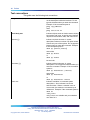
Text conventions
This guide uses the following text conventions.
angle brackets (< >)
Indicate that you choose the text to enter based
on the description inside the brackets. Do not
type the brackets when you enter the command.
Example: If the command syntax is
ping <ip_address>
enter
ping 192.32.10.12
bold body text
Indicates objects such as window names, dialog
box names, and icons, as well as user interface
objects such as buttons, tabs, and menu items.
braces ({})
Indicate required elements in syntax
descriptions where more than one option exists.
Choose only one of the options. Do not type the
braces when you enter the command. Example:
If the command syntax is
show ip {alerts|routes}
enter either
show ip alerts
or
show ip routes
but not both.
brackets ([ ])
Indicate optional elements in syntax
descriptions. Do not type the brackets when you
enter the command. Example: If the command
syntax is
show ip interfaces [-alerts]
enter either
show ip interfaces
or
show ip interfaces -alerts
italic text
Indicates variables in command syntax
descriptions. Also indicates new terms
and book titles. Where a variable is two or
more words, the words are connected by an
underscore. Example: If the command syntax is
show at
<valid_route>
valid_route is one variable and you substitute
one value for it.
Nortel Business Ethernet Switch 1000 Series
Using The Nortel Business Ethernet Switch 1000 Series
NN47927-300 01.01 Standard
1.1 10 January 2007
Copyright © 2007, Nortel Networks
.
Nortel Networks Confidential
How to get help
15
plain Courier text
Indicates command syntax and system output,
for example, prompts and system messages.
Example:
Set Trap Monitor Filters
separator ( > )
Shows menu paths.
Example: Protocols > IP identifies the IP
command on the Protocols menu.
vertical line ( | )
Separates choices for command keywords and
arguments. Enter only one of the choices. Do
not type the vertical line when you enter the
command.
Example: If the command syntax is
show ip {alerts|routes}
enter either
show ip alerts
or
show ip routes
but not both.
Related publications
For more information about using the BES1000 Series switch, see: Quick
Installation Guide for the Nortel Business Ethernet Switch 1000 (NN
You can print selected technical manuals and release notes for free, directly
from the Internet. Go to www.nortel.com. Find the product for which you
need documentation. Then, locate the specific category and model or
version for your hardware or software product. Use Adobe Reader to open
the manuals and release notes, search for the sections you need, and print
them on most standard printers. Go to www.adobe.com to download a
free copy of Adobe Reader.
How to get help
If you purchase a service contract for your Nortel product from a distributor
or authorized reseller, contact the technical support staff for that distributor
or reseller for assistance.
If you purchase a Nortel service program, contact Nortel Technical Support.
The following information is available online:
•
contact information for Nortel Technical Support
•
information about the Nortel Technical Solutions Centers
•
information about the Express Routing Code (ERC) for your product
Nortel Business Ethernet Switch 1000 Series
Using The Nortel Business Ethernet Switch 1000 Series
NN47927-300 01.01 Standard
1.1 10 January 2007
Copyright © 2007, Nortel Networks
.
Nortel Networks Confidential
16 Preface
An ERC is available for many Nortel products and services. When you use
an ERC, your call is routed to a technical support person who specializes in
supporting that product or service. You can locate the ERC for your product
or service online.
The Nortel Support Web page is at:
www.nortel.com
Nortel Business Ethernet Switch 1000 Series
Using The Nortel Business Ethernet Switch 1000 Series
NN47927-300 01.01 Standard
1.1 10 January 2007
Copyright © 2007, Nortel Networks
.
Nortel Networks Confidential
17
New in this release
The following section details what is new in Using the Nortel Business
Ethernet Switch 1000 Series (NN47927-301) for hardware and software
release 1.1:
Features
See the following sections for information about feature changes:
Release 1.0
The first release of Using the Nortel Business Ethernet Switch 1000 Series
Release 1.1
This is the second release of Using the Nortel Business Ethernet Switch
1000 Series. The document has been reorganized to indicate basic,
advanced, and administrative sections for the Web-based user interface
and the Element Manager.
Nortel Business Ethernet Switch 1000 Series
Using The Nortel Business Ethernet Switch 1000 Series
NN47927-300 01.01 Standard
1.1 10 January 2007
Copyright © 2007, Nortel Networks
.
Nortel Networks Confidential
18 New in this release
Nortel Business Ethernet Switch 1000 Series
Using The Nortel Business Ethernet Switch 1000 Series
NN47927-300 01.01 Standard
1.1 10 January 2007
Copyright © 2007, Nortel Networks
.
Nortel Networks Confidential
19
Introduction
The BES1000 Series switches are high performance Web-managed
switches that deliver performance and control to your network. The BES
1010-24T and BES 1010-48T versions provide 10/100/1000 autosensing
ports which include two shared Small Form-Factor Pluggable (SFP) Ports;
SFPs are hot-swappable products that enhance input and output and allow
gigabit Ethernet ports to link with other gigabit Ethernet ports over various
media types. Because SFPs use smaller connectors, they are easier to
use in high density applications and unlike an RJ-45 port, can connect two
optical fibers in the same space.
The BES 1020-24T-PWR and BES 1020-48T-PWR versions provide
10/100/1000 ports that include 12 and 24 Power over Ethernet (PoE) ports
which include two shared SFP Ports.
Navigation
•
To set up the Web UI for use with the BES1000, see "Using the
Web-based user interface" (page 21).
•
To set up the BES1000 management features using the Web UI, see
"BES1000 basic configuration using the Web-based user interface"
(page 37), and "BES1000 advanced features configuration" (page 59).
•
To set up the Element Manager for use with the BES1000, see "Using
the Element Manager user interface" (page 85).
•
To set up the BES1000 management features using the Element
Manager, see "BES1000 basic configuration using Element Manager
" (page 89) and "BES1000 advanced configuration using Element
Manager" (page 111).
•
To reset the system, to change the IP address, to view system details,
or to manage BES1000 firmware, see "BES1000 administration" (page
121).
•
To learn about the BES1000 management features, see "BES1000
fundamentals" (page 209).
Nortel Business Ethernet Switch 1000 Series
Using The Nortel Business Ethernet Switch 1000 Series
NN47927-300 01.01 Standard
1.1 10 January 2007
Copyright © 2007, Nortel Networks
.
Nortel Networks Confidential
20 Introduction
•
For system defaults, specifications, compliances, and other reference
information related to the BES1000, see "BES reference information"
(page 253).
Nortel Business Ethernet Switch 1000 Series
Using The Nortel Business Ethernet Switch 1000 Series
NN47927-300 01.01 Standard
1.1 10 January 2007
Copyright © 2007, Nortel Networks
.
Nortel Networks Confidential
21
Using the Web-based user interface
Use this information to understand how to use the Web-based user interface
to view and configure information about the BES1000 Series switch.
Prerequisites for using the Web-based user interface
To use the Web-based user interface, you need the following items:
•
a computer connected to a network port that is a member of the
management Virtual LAN (VLAN)
•
one of the following Web browsers or Web engines installed on your
computer:
— Windows 95™, Windows 98™, Windows 2000™, Windows XP™, or
Windows NT™ 5.1; en-US; rv:1.8.0.3, rv:1.7.5, and UNIX installed
on the computer
— Internet Explorer™ 6.0 and later
You will need to disable the cache option on the Browser you use. This
issue is generated by a known issue regarding cache pages stored
by Microsoft Internet Explorer (See Bulletin # 234067 in the Microsoft
Knowledge Base Web page).
ATTENTION
The Web pages of the Web-based management interface can load at different
speeds depending on which Web browser you use.
CAUTION
Web browser capabilities such as page bookmarking, refresh,
page forward, and page back function the same as any other
Web site. However, these capabilities do not enhance the
functionality of the Web-based management interface. Nortel
recommends that you use only the navigation tools provided
in the management interface.
Nortel Business Ethernet Switch 1000 Series
Using The Nortel Business Ethernet Switch 1000 Series
NN47927-300 01.01 Standard
1.1 10 January 2007
Copyright © 2007, Nortel Networks
.
Nortel Networks Confidential
22 Using the Web-based user interface
•
the IP address of the BES1000 Series switch. For information about
setting the IP address of the switch, see "Configuring initial settings by
using the Quick Start feature" (page 37).
ATTENTION
To use some of the BES1000 Series switch Web-based management
functionality, such as downloading software, you must connect your Trivial File
Transfer Protocol (TFTP) server to a BES1000 Series switch.
Navigation
•
"Setting up the Web-based user interface " (page 22)
•
"Logging on to the Web-based management interface" (page 23)
•
"Logging off from the Web-based management interface" (page 23)
•
"Navigating the Web-based user interface" (page 24)
•
"Setting the IP address" (page 26)
•
"Setting the IP address automatically" (page 27)
•
"Changing the administrator password" (page 29)
•
"Configuring system information " (page 32)
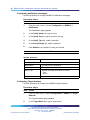
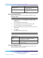
Setting up the Web-based user interface
Nortel recommends that you follow the procedures in this section regarding
Web-based user interface prerequisites before you use the management
features of your switch for the first time.
Procedure steps
Step
Action
1
Check that Java Runtime Environment (JRE) version 1.50_07-b03
or later is installed on your PC. Download the latest version from
www.java.com if required.
ATTENTION
The menu on the left-hand side of the Web-based user interface may not
appear if the Java Runtime Environment (JRE) is not installed.
2
Ensure the software programs on your PC enable Java script and
Java applets, and Web browser pop-up dialog boxes. Refer to the
corresponding software documentation for instructions. Software
programs include but are not limited to:
•
Web browser
•
firewall
Nortel Business Ethernet Switch 1000 Series
Using The Nortel Business Ethernet Switch 1000 Series
NN47927-300 01.01 Standard
1.1 10 January 2007
Copyright © 2007, Nortel Networks
.
Nortel Networks Confidential
Logging off from the Web-based management interface 23
•
software that controls Java behavior
ATTENTION
The menu on the left-hand side of the Web-based user interface may
not appear if Java script and Java applets are disabled, and some
management features do not work properly if pop-up dialog boxes are
disabled.
—End—
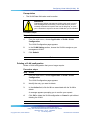
Logging on to the Web-based management interface
Use this procedure to log on to the Web-based user interface.
Before you log on to the Web-based management interface, verify the VLAN
port assignments and ensure that your switch and computer are assigned to
the same VLAN. If the devices are not connected to the same VLAN, the
IP address does not display on the home page.
The Default IP address is 192.168.1.132, and the security default is ON.
The default Username is: nnadmin; the default Password is: PlsChgMe!
The password and user name are case-sensitive.
Use this procedure to log on to the Web-based user interface.
Procedure steps
Step
Action
1
Start your Web browser.
2
In the address bar, type the IP address for your host switch, for
example, http://192.168.151.175, and press Enter.
—End—
Network security is enabled by default.
Logging off from the Web-based management interface
Log off from the Web-based user interface after you finish using the switch.
Procedure steps
Step
Action
1
From the main menu, choose Administration > Logout.
A logout message appears.
Nortel Business Ethernet Switch 1000 Series
Using The Nortel Business Ethernet Switch 1000 Series
NN47927-300 01.01 Standard
1.1 10 January 2007
Copyright © 2007, Nortel Networks
.
Nortel Networks Confidential
24 Using the Web-based user interface
2
Click OK to log off or click Cancel to cancel the request.
—End—
ATTENTION
If you do not configure system password security, a log off returns you to the
home page. If you configure system password security, a log off returns you
to a log on page.
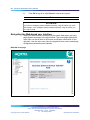
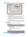
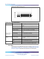
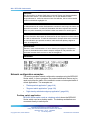
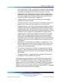
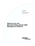
Navigating the Web-based user interface
When your Web browser connects with the switch Web agent, the home
page appears as shown in the figure below. The home page displays the
main menu on the left side of the screen and System information on the
right side. Use the main menu links to navigate to other menus and display
configuration parameters and statistics.
BES1000 home page
Nortel Business Ethernet Switch 1000 Series
Using The Nortel Business Ethernet Switch 1000 Series
NN47927-300 01.01 Standard
1.1 10 January 2007
Copyright © 2007, Nortel Networks
.
Nortel Networks Confidential
Navigating the Web-based user interface 25
Menu and management pages
The menu is the same for all pages. It contains a list of six main headings.
To navigate the Web-based user interface menu, click a menu title and
then click one of its options. When you click an option, the corresponding
page appears.
The first five headings provide options for viewing and configuring switch
parameters. The Support heading provides options to open the online Help
file and the Nortel Web site. Tools are provided in the menu to assist you in
navigating the Web-based management interface.
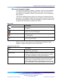
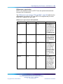
Menu icons
Icon
Description
This icon identifies a menu title. Click on this icon to display
its options.
This icon identifies a menu title option. Click on this icon to
display the corresponding page.
This icon identifies a menu title option that has a hyperlink
to related pages.
This icon is linked to an action, for example, log off, reset, or
reset to system defaults.
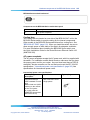
When you click a menu option, the corresponding management page
appears. A page is composed of one or more items.
Management page items
Item
Description
Tables and input forms
Gray cells are read only.
White cells are input fields.
Check boxes
Enable or disable a selection by clicking a check box. When a
check mark is displayed in the box, that selection is enabled.
You disable a selection by clicking the checked box.
Icons and buttons
Icons and buttons perform an action concerning the displayed
page or the switch. Some pages include a button that opens
another page or updates the values shown on the current
page. Some pages include icons that initiate an action, such
as reformatting the current displayed data as a bar or pie chart.
Nortel Business Ethernet Switch 1000 Series
Using The Nortel Business Ethernet Switch 1000 Series
NN47927-300 01.01 Standard
1.1 10 January 2007
Copyright © 2007, Nortel Networks
.
Nortel Networks Confidential
26 Using the Web-based user interface
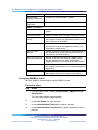
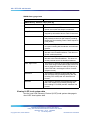
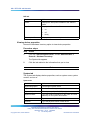
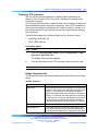
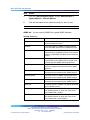
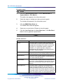
Configuration options
Configurable parameters have a dialog box or a drop-down list. After you
make a configuration change on a page, be sure to click the Submit button
to confirm the new setting. The following table summarizes some of the
common configuration buttons that appear throughout the Web-based user
interface pages.
Web Page configuration buttons
Button
Action
Submit
Saves specified values to the system.
Reload
Refreshes the page with current values.
Add
Adds the selected parameter to the configuration.
Delete
Deletes the selected parameter from the configuration.
Remove
Removes the selected parameter from the configuration.
Help
Links directly to Web Help.
ATTENTION
To ensure proper screen refresh, in the Internet Explorer menu, choose Tools
> Internet Options > General > Temporary Internet Files > Settings and
select Every visit to the page as the setting for Check for newer versions of
stored pages.
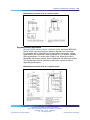
Setting the IP address
Use this procedure to configure an IP address for the switch.
To use the BES1000 management features, you must first configure the
switch with an IP address that is compatible with the network where it
is being installed. For simplicity, configure the IP address before you
permanently install the switch.
Procedure steps
Step
Action
1
Place your switch close to the PC that you will use to configure it.
It helps if you can see the front panel of the switch while you work
on your PC.
2
Connect the Ethernet port of your PC to any port on the front panel
of your switch.
3
Insert the power adapter into the DC power socket in front of the
switch.
4
Plug the other end of the power adapter into a grounded, 3-pin
socket, AC power source.
Nortel Business Ethernet Switch 1000 Series
Using The Nortel Business Ethernet Switch 1000 Series
NN47927-300 01.01 Standard
1.1 10 January 2007
Copyright © 2007, Nortel Networks
.
Nortel Networks Confidential
Setting the IP address 27
5
Check the front-panel LEDs as the device powers on to confirm that
the PWR LED is green. If not, check that the power cable is correctly
plugged in.
6
If the PC IP address is different from the switch but is on the same
subnet, go to the next step. (For example, if the PC and switch both
have addresses that start with 192.168.1.x.) Otherwise, manually
set the IP address for the PC. See Changing a PC IP address. The
default IP address of the switch is 192.168.1.132, the default subnet
mask is 255.255.255.0, and the default gateway is 0.0.0.0.
7
Open your Web browser and enter the IP address of the switch, for
example, http://192.168.1.132. If you do not see the logon page,
check your IP address and repeat step 3.
8
If prompted, enter the default user name nnadmin and default
password PlsChgMe!, and click Login.
9
From the main menu, click Configuration > IP.
10
On the IP Settings page, select a BootP request mode.
11
Enter an IP address followed by the new switch IP address, subnet
mask, default gateway.
12
Click Submit.
—End—
No other configuration changes are required at this stage, but Nortel
recommends that you change the administrator password and enable
password authentication before you log off.
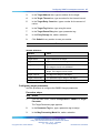
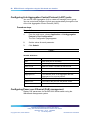
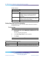
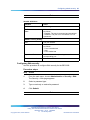
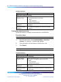
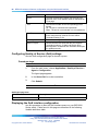
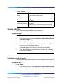
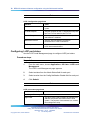
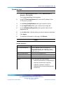
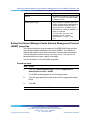
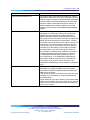
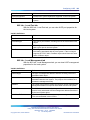
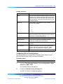
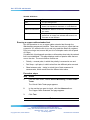
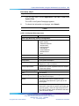
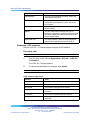
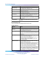
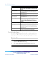
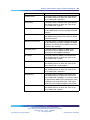
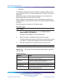
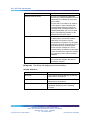
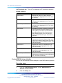
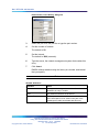
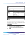
Setting the IP address automatically
You can use an IP address to manage access to the switch over your
network. By default, the switch invokes BootP at startup to obtain an IP
address for the user interface. If you want to configure the user interface IP
address manually, you can power the BES without a BootP server present
and browse to the factory default address for the user interface.
Prerequisites
•
To configure the switch dynamically, the network must provide BOOTP
services.
Procedure steps
Nortel Business Ethernet Switch 1000 Series
Using The Nortel Business Ethernet Switch 1000 Series
NN47927-300 01.01 Standard
1.1 10 January 2007
Copyright © 2007, Nortel Networks
.
Nortel Networks Confidential
28 Using the Web-based user interface
Step
Action
1
From the main menu, choose Configuration > IP.
2
In the BootP Request Mode box, choose the type of BootP mode
you want.
3
Click Submit.
If BOOTP is enabled, the switch broadcasts a request for IP
configuration settings on each power reset.
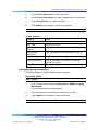
—End—
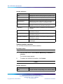
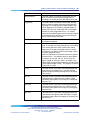
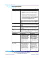
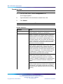
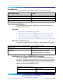
Variable definitions
Variable
Value
BootP Request Mode
Choose from:
•
BootP or Default IP
•
BootP always
•
BootP Disabled
•
BootP or Last Address
BootP or Default IP:
This setting sends a BootP request when the switch IP address
stored in nonvolatile memory is the factory default value. If the
stored IP address differs from the factory default value, the switch
uses the stored network parameters. If the switch cannot find a
BootP server, it tries five more times to find one and then defaults
to the factory settings.
BootP Always:
This setting ignores the stored network parameters and sends a
BootP request each time the switch boots. If the BootP request
fails, the switch boots with the factory default IP configuration. This
setting disables remote management if no BootP server is set up
for the switch, but it lets the switch boot normally.
BootP Disabled:
This setting uses the IP configuration parameters stored in
nonvolatile memory each time the switch boots. If a BootP
configuration is in progress when you issue this command, the
BootP configuration stops.
BootP or Last Address:
This setting obtains the IP configuration using BootP at each
start up. If the BootP request fails, the switch uses the network
parameters stored in its nonvolatile memory.
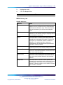
Nortel Business Ethernet Switch 1000 Series
Using The Nortel Business Ethernet Switch 1000 Series
NN47927-300 01.01 Standard
1.1 10 January 2007
Copyright © 2007, Nortel Networks
.
Nortel Networks Confidential
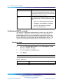
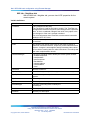
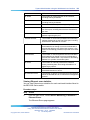
Changing the administrator password 29
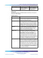
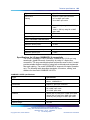
Variable
Value
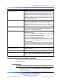
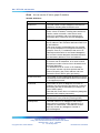
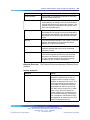
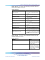
Note: Valid parameters obtained in using BootP always replace
current information stored in the nonvolatile memory.
Note: Whenever the switch broadcasts BootP requests, the BootP
process times out if a reply is not received within approximately 60
seconds. When the process times out, the BootP request mode
automatically changes to BootP Disabled mode. To restart the
BootP process, change the BootP request mode to any of the two
following modes: BootP Always, or to BootP or Last Address.
IP Address
Type a new IP address in the appropriate format.
Switch IP Address
Type a new switch IP address in the appropriate format. The
default switch IP address is 192.168.1.32
Note: When the IP address is entered in the In-Band IP Address
field, and the In-Band Subnet Mask field value is not present, the
software provides an in-use default value for the In-Band Subnet
Mask field that is based on the class of the IP address entered in the
In-Band IP Address field.
Subnet Mask
Type a new subnet mask in the appropriate format. The default
subnet mask value is 255.255.255.0.
Default Gateway
Type an IP address for the default gateway in the appropriate
format. The default gateway value is 192.168.1.1.
Administration
username: nnadmin
password: PlsChgMe!
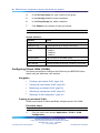
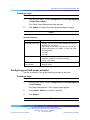
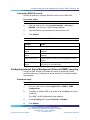
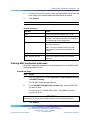
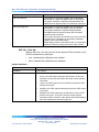
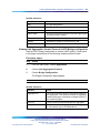
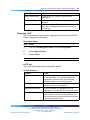
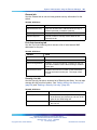
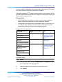
Changing the administrator password
Use the Web, Console, and Remote Authentication Dial-In User Service
(RADIUS) pages to change access passwords. RADIUS is a client /
server-based authentication software system that provides secure Internet
access, especially in a Virtual Private Network (VPN). When a RADIUS
password is used for dial in access to an Internet Service Provider (ISP), the
username and password are checked and if they are correct, the RADIUS
server authorizes access to the ISP systems and network. Because
the administration of user profiles within an authentication database is
centralized in a RADIUS system, support for multiple VPN switches is
simplified.
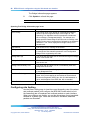
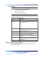
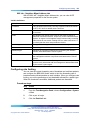
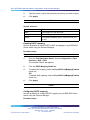
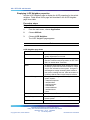
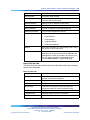
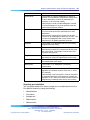
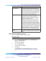
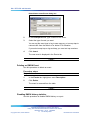
Configuring Web security
Use this procedure to configure Web security for the BES1000.
Procedure steps
Step
Action
1
From the main menu, choose Administration > Security > Web.
Nortel Business Ethernet Switch 1000 Series
Using The Nortel Business Ethernet Switch 1000 Series
NN47927-300 01.01 Standard
1.1 10 January 2007
Copyright © 2007, Nortel Networks
.
Nortel Networks Confidential
30 Using the Web-based user interface
The Security > Web page appears.
2
In the Web Switch Password Type list, select a new password type.
3
In the Read-Only Switch Password box, type a new read-only
access password.
4
In the Read-Write Switch Password box, type a new read-write
access password.
5
Click Submit.
—End—
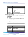
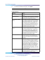
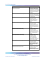
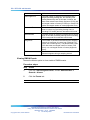
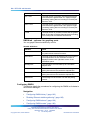
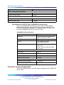
Variable definitions
Variable
Value
Web Switch Password Setting
Web Switch
Password Type
Select a password type to use to access the Web
interface. The password type is as follows:
- None
- Local Password
- RADIUS Authentication
Read-Only Switch
Password
Specify the read-only password for access to the Web
interface.
Read-Write Switch
Password
Specify the read-write password for access to the Web
interface.
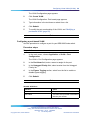
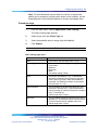
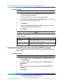
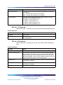
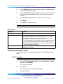
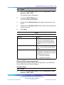
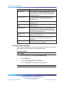
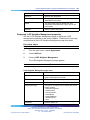
Configuring RADIUS security
Use this procedure to configure RADIUS security for the BES1000.
Procedure steps
Step
Action
1
From the main menu, choose Administration > Security > RADIUS.
The Security > RADIUS page appears.
2
In the Primary RADIUS Server box, type the address of the primary
RADIUS server address.
3
In the Secondary RADIUS Server box, type the address of the
secondary RADIUS server address.
4
In the UDP RADIUS Port box, type the port number for User
Datagram Protocol (UDP).
Nortel Business Ethernet Switch 1000 Series
Using The Nortel Business Ethernet Switch 1000 Series
NN47927-300 01.01 Standard
1.1 10 January 2007
Copyright © 2007, Nortel Networks
.
Nortel Networks Confidential
Changing the administrator password 31
5
In the RADIUS Shared Secret box, type a password string for your
RADIUS server.
6
Click Submit.
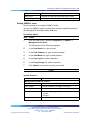
—End—
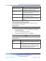
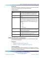
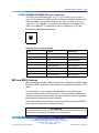
Variable
Value
RADIUS Authentication Setting
Primary RADIUS
Server
The address of the primary RADIUS server address.
Secondary RADIUS
Server
The address of the secondary RADIUS server address.
UDP RADIUS Port
The port number for User Datagram Protocol (UDP).
RADIUS Shared
Secret
The password string for your RADIUS server. You can
use up to 128 characters.
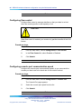
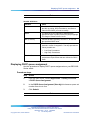
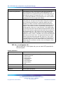
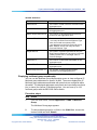
Configuring console security
Use this procedure to configure console security for the BES1000.
Procedure steps
Step
Action
1
From the main menu, choose Administration > Security >
Console.
The Security > Console page appears.
2
In the Console Switch Password Type list, select a new password
type.
3
In the Read-Only Switch Password box, type a new read-only
access password.
4
In the Read-Write Switch Password box, type a new read-write
access password.
5
Click Submit.
—End—
Nortel Business Ethernet Switch 1000 Series
Using The Nortel Business Ethernet Switch 1000 Series
NN47927-300 01.01 Standard
1.1 10 January 2007
Copyright © 2007, Nortel Networks
.
Nortel Networks Confidential
32 Using the Web-based user interface
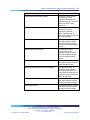
Variable definitions
Variable
Value
Console Switch Password Setting
Console Switch
Password Type
Select a password type to use to get console access to
the switch. The password type is as follows:
- None
- Local Password
- RADIUS Authentication
Read-Only Switch
Password
Specify the read-only password for console access to
the switch.
Read-Write Switch
Password
Specify the read-write password for console access
to the switch.
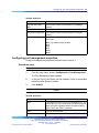
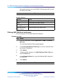
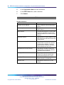
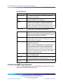
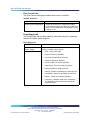
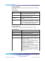
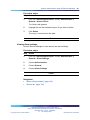
Configuring system information
Use the System page to provide a descriptive name, location, and contact
information to the system. The configurable parameters on the System page
are displayed in a read-only format on the System Information home page.
Procedure steps
Step
Action
1
From the main menu, choose Configuration > System.
The System page appears.
2
Type a contact name, system name, and system location information.
3
Click Submit.
—End—
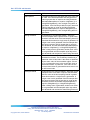
Variable definitions
Variable
Value
System Description
The factory set description of the hardware and
software versions.
System Object ID
The object identifier (OID) for the system.
System Up Time
The elapsed time since the system is last reinitialized.
Note: This field is updated only when the screen is
redisplayed.
Nortel Business Ethernet Switch 1000 Series
Using The Nortel Business Ethernet Switch 1000 Series
NN47927-300 01.01 Standard
1.1 10 January 2007
Copyright © 2007, Nortel Networks
.
Nortel Networks Confidential
Help screens
33
Variable
Value
System Contact
Administrator responsible for the system. The range
of values is from 1 to 255 characters in length.
System Name
A name assigned to the switch system. The range of
values is from 1 to 255 characters in length.
System Location
The system location. The range of values is from 1 to
255 characters in length.
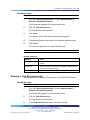
Help screens
Use these procedures to access the BES1000 help screens.
Accessing BES1000 help
Procedure steps
Step
Action
1
From the main menu, choose Support > Help.
The Online Help table of contents for the BES1000 Series Switch
appears.
2
Scroll through the entries or click a link on a topic to see information
about the topic.
—End—
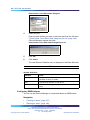
Accessing BES1000 release notes
Procedure steps
Step
Action
1
From the main menu, choose Support > Release Notes.
The Nortel Technical Support page appears.
2
Select BES1000 series products from the Product Category,
Products A-Z, or Product Families lists.
3
Choose a product from the list that appears.
4
Choose the type of content from the list.
5
Click Go.
6
To clear the entries from the fields in this screen, click Reset.
Nortel Business Ethernet Switch 1000 Series
Using The Nortel Business Ethernet Switch 1000 Series
NN47927-300 01.01 Standard
1.1 10 January 2007
Copyright © 2007, Nortel Networks
.
Nortel Networks Confidential
34 Using the Web-based user interface
—End—
Accessing BES1000 manuals
Procedure steps
Step
Action
1
From the main menu, choose Support > Manuals.
The Nortel Technical Support page appears.
2
Select BES1000 series products from the Product Category,
Products A-Z, or Product Families lists.
3
Choose a product from the list that appears.
4
Choose the type of content from the list.
5
Click Go.
6
To clear the entries from the fields in this screen, click Reset.
—End—
Accessing the management interface
Log on to the Web-based management interface to use the application. With
Web access enabled, the switch can support a maximum of five concurrent
Web page users. Two predefined user levels are available, and each user
level has a corresponding user name and password.
The password for the Read-Only Community String is: PlsChgMe!RO;
the password for the Read-Write Community String is: PlsChgMe!RW.
The passwords are case sensitive.
Procedure steps
Step
Action
1
Open a web browser.
2
In the Address bar, type the Address URL or IP address of the
BES1000.
3
In the Username box, type a valid user name.
Default values are nnadminRO [lowercase] for read-only access or
nnadmin [lowercase] for read/write access.
Nortel Business Ethernet Switch 1000 Series
Using The Nortel Business Ethernet Switch 1000 Series
NN47927-300 01.01 Standard
1.1 10 January 2007
Copyright © 2007, Nortel Networks
.
Nortel Networks Confidential
Accessing the management interface 35
4
In the Password box, type your password.
Default values are PlsChgMe!RO for read-only access or
PlsChgMe! for read/write access.
5
Click Log On.
The System Information page appears.
—End—
Nortel Business Ethernet Switch 1000 Series
Using The Nortel Business Ethernet Switch 1000 Series
NN47927-300 01.01 Standard
1.1 10 January 2007
Copyright © 2007, Nortel Networks
.
Nortel Networks Confidential
36 Using the Web-based user interface
Nortel Business Ethernet Switch 1000 Series
Using The Nortel Business Ethernet Switch 1000 Series
NN47927-300 01.01 Standard
1.1 10 January 2007
Copyright © 2007, Nortel Networks
.
Nortel Networks Confidential
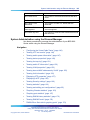
37
BES1000 basic configuration using the
Web-based user interface
Use these procedures to manage the basic configuration of your BES1000
Series switch.
Navigation
•
"Configuring initial settings by using the Quick Start feature" (page 37)
•
"Configuring Simple Network Management Protocol (SNMP)" (page 39)
•
"Configuring SNMPv3 management access" (page 41)
•
"Configuring Virtual LANs (VLANs)" (page 48)
•
"Configuring Link Aggregation Control Protocol (LACP) ports" (page 52)
•
"Configuring Power over Ethernet (PoE) management" (page 52)
•
"Viewing Spanning Tree Port information" (page 54)
•
"Viewing Spanning Tree Bridge information" (page 55)
•
"Configuring rate limiting" (page 56)
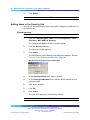
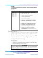
Configuring initial settings by using the Quick Start feature
Configure initial settings by using the Quick Start feature which can
consolidate multiple setup pages into a single page. The Quick Start screen
can be used to configure the following information:
•
switch IP address
•
subnet mask
•
default gateway
•
default (Management VLAN)
•
Web passwords
During the initial setup mode, all ports in the switch are assigned to the
new default VLAN.
Nortel Business Ethernet Switch 1000 Series
Using The Nortel Business Ethernet Switch 1000 Series
NN47927-300 01.01 Standard
1.1 10 January 2007
Copyright © 2007, Nortel Networks
.
Nortel Networks Confidential
38 BES1000 basic configuration using the Web-based user interface
A port-based Quick Start VLAN is created if the new default VLAN does not
exist. All ports are removed from the current default VLAN and are assigned
to the Quick Start VLAN. The Port VLAN ID (PVIDs) for all ports are
changed to the Quick Start VLAN. The Quick Start VLAN is also designated
as the management VLAN.
Procedure steps
Step
Action
1
From the main menu, select Administration > Quick Start.
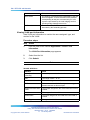
The Quick Start page is displayed.
2
Type the IP address, subnet mask, default gateway, default
management VLAN, select a password type, type a read-only
password, and a read-write password.
3
Click Submit after making the required settings.
—End—
Variable definitions
Variable
Value
Switch IP Address
Specify a new IP address for the switch.
Subnet Mask
Enter a new subnet mask.
Default Gateway
Specify an IP address for the default gateway.
Default (Management)
VLAN
Specify the VLAN ID number of the port-based default
management VLAN.
Web Switch Password
Type
Select one of the following types for password access
to the Web interface:
•
None
•
Local Password
•
RADIUS Authentication
Read-Only Switch
Password
Specifies the read-only password for access to the
Web interface.
Read-Write Switch
Password
Specifies the read/write password for access to the
Web interface.
Nortel Business Ethernet Switch 1000 Series
Using The Nortel Business Ethernet Switch 1000 Series
NN47927-300 01.01 Standard
1.1 10 January 2007
Copyright © 2007, Nortel Networks
.
Nortel Networks Confidential
Configuring an SNMP trap receiver 39
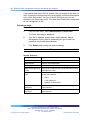
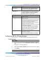
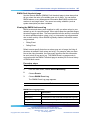
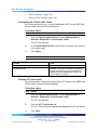
Configuring Simple Network Management Protocol (SNMP)
Configure an SNMPv1 to configure an IP address and community string.
You can also use SNMPv1 to modify read/write and read-only community
strings, enable or disable trap mode settings, and/or enable or disable the
autotopology feature.
Procedure steps
Step
Action
1
From the main menu, choose Configuration > SNMPv1.
The SNMPv1 page appears.
2
Type information in the text boxes or select from a list.
3
Click Submit in any section to save your changes.
—End—
Variable definitions
Variable
Value
Community String Setting
Read-Only
Community String
Type in the read-only password. (Default:
PlsChgMe!RO). The password can be from 1 to 32
characters in length.
Read-Write
Community String
Type in the read-write password. (Default:
PlsChgMe!RW). The password can be from 1 to 32
characters in length.
Trap Mode Setting
AuthenticationTrap
Choose to enable or disable the authentication trap:
- Enable
- Disable
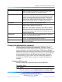
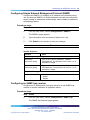
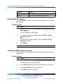
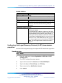
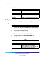
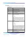
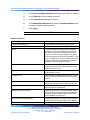
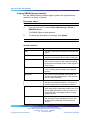
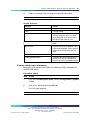
Configuring an SNMP trap receiver
Configure an IP address and community string for a new SNMP trap
receiver to receive notification of significant events.
Procedure steps
Step
Action
1
From the main menu, choose Configuration > SNMP Trap.
The SNMP Trap Receiver page appears.
Nortel Business Ethernet Switch 1000 Series
Using The Nortel Business Ethernet Switch 1000 Series
NN47927-300 01.01 Standard
1.1 10 January 2007
Copyright © 2007, Nortel Networks
.
Nortel Networks Confidential
40 BES1000 basic configuration using the Web-based user interface
2
In the Trap Receiver Creation section type information in the text
boxes, or select from a list.
3
Click Submit.
The new entry is displayed in the Trap Receiver Table.
—End—
Variable definitions
Variable
Value
Deletes the row.
Trap Receiver Index
Choose the number of the trap receiver to create or
modify.
The range is from 1 to 4.
IP Address
Type the network address of the SNMP manager that
is to receive the specified trap.
Use the following format: XXX.XXX.XXX.XXX
Community
Type the community string for the specified trap
receiver.
The range is from 0 to 32 characters.
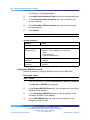
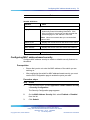
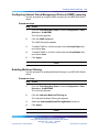
Deleting an SNMP trap receiver configuration
Delete SNMP trap receiver configurations that you no longer need.
Procedure steps
Step
Action
1
From the main menu, choose Configuration > SNMP Trap.
The SNMP Trap Receiver page appears.
2
In the Trap Receiver Table, click the Delete icon ( X) for the entry
you want to delete.
A message appears prompting you to confirm your request.
3
Click OK to confirm or Cancel to quit without deleting the entry.
—End—
Nortel Business Ethernet Switch 1000 Series
Using The Nortel Business Ethernet Switch 1000 Series
NN47927-300 01.01 Standard
1.1 10 January 2007
Copyright © 2007, Nortel Networks
.
Nortel Networks Confidential
Configuring SNMPv3 management access 41
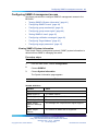
Configuring SNMPv3 management access
Use these procedures to configure SNMPv3 management access to the
BES1000.
•
"Viewing SNMPv3 System information" (page 41)
•
"Configuring SNMPv3 users" (page 42)
•
"Configuring group membership" (page 43)
•
"Configuring group access rights" (page 44)
•
"Setting SNMPv3 views" (page 45)
•
"Configuring notification messages" (page 46)
•
"Configuring Target Address" (page 46)
•
"Configuring target parameters" (page 47)
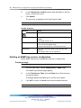
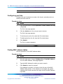
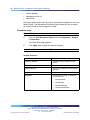
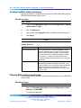
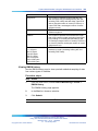
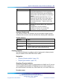
Viewing SNMPv3 System information
View simple network management protocol (SNMP) system information to
determine how SNMP is managing the switch.
Procedure steps
Step
Action
1
From the main menu, choose Configuration.
2
Choose SNMPv3.
3
Choose System Information.
The System Information page appears.
—End—
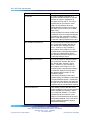
Variable definitions
Variable
Value
System Information
SNMP Engine ID
The SNMP address.
SNMP Engine Boots
The number of times SNMP has been activated.
SNMP Engine Time
The amount of time the engine has been active.
SNMP Engine
Maximum Message
Size
The message size in bytes that the engine supports.
SNMP Engine
Dialects
The versions of SNMP that are supported.
Nortel Business Ethernet Switch 1000 Series
Using The Nortel Business Ethernet Switch 1000 Series
NN47927-300 01.01 Standard
1.1 10 January 2007
Copyright © 2007, Nortel Networks
.
Nortel Networks Confidential
42 BES1000 basic configuration using the Web-based user interface
Variable
Value
Authentication
Protocols Supported
The types of protocols SNMP supports.
Private Protocols
Supported
Indicates whether private protocols are supported.
SNMP V3 Counters
Unavailable Contexts
Number of SNMP proxy requests to unavailable
entities.
Unknown Contexts
Number of SNMP proxy requests to unknown entities.
Unsupported Security
Levels
Number of packets received by the SNMP engine that
are dropped because they requested a security level
that is unknown to the SNMP.
Not In Time Windows
Number of packets received by the SNMP engine that
are dropped because they appeared outside of the
authoritative SNMP window.
Unknown User
Names
Number of packets received by the SNMP engine that
are dropped because they referenced a user that is
not known to the SNMP engine.
Unknown Engine IDs
Number of packets received by the SNMP engine
that are dropped because they referenced an
snmpEngineID that is not known to the SNMP engine.
Wrong Digests
Number of packets received by the SNMP engine that
are dropped because they do not contain the expected
digest value.
Decryption Errors
Number of packets received by the SNMP engine that
are dropped because they cannot be decrypted.
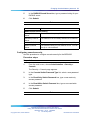
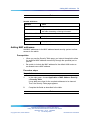
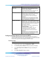
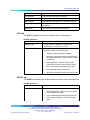
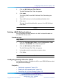
Configuring SNMPv3 users
Use the SNMPv3 Users page to assign SNMPv3 users.
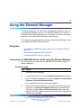
Procedure steps
Step
Action
1
From the main menu, choose Configuration > SNMPv3 > User
Specification.
The User Specification page appears.
2
In the User Name box, type a name.
3
In the Authentication Protocol list, make a selection.
4
In the Authentication Passphrase box, type a passphrase for the
protocol.
Nortel Business Ethernet Switch 1000 Series
Using The Nortel Business Ethernet Switch 1000 Series
NN47927-300 01.01 Standard
1.1 10 January 2007
Copyright © 2007, Nortel Networks
.
Nortel Networks Confidential
Configuring SNMPv3 management access 43
5
In the Privacy Protocol list, make a selection.
6
In the Privacy Passphrase box, type a passphrase for the protocol.
7
In the Entry Storage list, make a selection.
8
Click Submit in any section to save your changes.
—End—
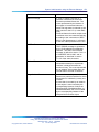
Variable definitions
Variable
Value
User Specification Creation
User Name
Type a user name.
Authentication
Protocol
Indicates which authentication protocol is in use.
Authentication
Passphrase
Type a passphrase for the authentication protocol.
Privacy Protocol
Indicates None if no privacy protocol is used.
Privacy Passphrase
Type a passphrase to use that is at least eight
characters in length.
Entry Storage
Choose whether the storage is volatile or nonvolatile.
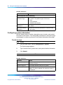
Configuring group membership
Use this procedure to assign SNMPv3 users to groups.
Procedure steps
Step
Action
1
From the main menu, choose Configuration > SNMPv3 > Group
Membership.
The Group Membership page appears.
2
Type information in the text boxes or choose from a list.
3
Click Submit in any section to save your entries.
—End—
Nortel Business Ethernet Switch 1000 Series
Using The Nortel Business Ethernet Switch 1000 Series
NN47927-300 01.01 Standard
1.1 10 January 2007
Copyright © 2007, Nortel Networks
.
Nortel Networks Confidential
44 BES1000 basic configuration using the Web-based user interface
Variable definitions
Variable
Value
Group Membership Creation
Security Name (i.e.
User Name)
Type a user name for the SNMPv3 group.
Security Model
Choose the SNMP type.
•
SNMPv1
•
SNMPv2c
•
USM
Group Name
Type a name to identify the group.
Entry Storage
Choose whether the storage is volatile or nonvolatile.
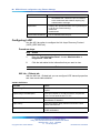
Configuring group access rights
Use this procedure to configure the access rights for each SNMPv3 group.
Procedure steps
Step
Action
1
From the main menu, choose Configuration > SNMPv3 > Group
Access Rights.
The Group Access Rights page appears.
2
Type information in the text boxes or choose from a list.
3
Click Submit in any section to save your entries.
—End—
Variable definitions
Variable
Value
Group Access Creation
Group Name
Type a name to identify the group.
Security Model
Choose the SNMP type.
Security Level
Choose an authentication and privilege level.
Read View
Indicate the SNMP group that has read-only access.
Write View
Indicate the SNMP group that has write access.
Nortel Business Ethernet Switch 1000 Series
Using The Nortel Business Ethernet Switch 1000 Series
NN47927-300 01.01 Standard
1.1 10 January 2007
Copyright © 2007, Nortel Networks
.
Nortel Networks Confidential
Configuring SNMPv3 management access 45
Variable
Value
Notify View
Indicate the SNMP group that has notify access.
Entry Storage
Choose whether the storage is volatile or nonvolatile.
Setting SNMPv3 views
Use this procedure to configure SNMPv3 views.
You can use SNMPv3 views to restrict user access to specified portions of
the Management Information Base (MIB) tree.
Procedure steps
Step
Action
1
From the main menu, choose Configuration > SNMPv3 >
Management Info View.
The Management Info View page appears.
2
In the View Name box, type a name,
3
In the View Subtree box, type a subnet address.
4
In the View Mask box, type a mask address.
5
In the View Type list, make a selection.
6
In the Entry Storage list, make a selection.
7
Click Submit in any section to save your entries.
—End—
Variable definitions
Variable
Value
Management Information Creation
View Name
The name for the SNMP group.
View Subtree
The subnet address to assign to the group.
View Mask
The mask address to assign to the group.
View Type
Indicate the view type as follows:
- Include
- Exclude
Entry Storage
Choose whether the storage is volatile or nonvolatile.
Nortel Business Ethernet Switch 1000 Series
Using The Nortel Business Ethernet Switch 1000 Series
NN47927-300 01.01 Standard
1.1 10 January 2007
Copyright © 2007, Nortel Networks
.
Nortel Networks Confidential
46 BES1000 basic configuration using the Web-based user interface
Configuring notification messages
Use this procedure to configure SNMPv3 notification messages.
Procedure steps
Step
Action
1
From the main menu, choose Configuration > SNMPv3 >
Notification.
The Notification page appears.
2
In the Notify Name box, type a name.
3
In the Notify Tag box, type a name for the tag.
4
In the Notify Type list, make a selection.
5
In the Entry Storage list, make a selection.
6
Click Submit in any section to save your entries.
—End—
Variable definitions
Variable
Value
Notification Creation
Notify Name
The name for the notification.
Notify Tag
The tag for the notification.
Notify Type
Indicate the SNMP notification as follows:
- Trap
- Inform
Entry Storage
Choose whether the storage is volatile or nonvolatile.
Configuring Target Address
Use this procedure to configure the SNMPv3 target address.
Procedure steps
Step
Action
1
From the main menu, choose Configuration > SNMPv3 > Target
Address.
The Target Address page appears.
2
In the Target Name box, type a target name.
Nortel Business Ethernet Switch 1000 Series
Using The Nortel Business Ethernet Switch 1000 Series
NN47927-300 01.01 Standard
1.1 10 January 2007
Copyright © 2007, Nortel Networks
.
Nortel Networks Confidential
Configuring SNMPv3 management access 47
3
In the Target Address box, type an address for the target.
4
In the Target Timeout box, type a number for the timeout interval.
5
In the Target Retry Count box, type a number for the amount of
retries.
6
In the Target Tag List box, type a tag list name.
7
In the Target Param Entry box, type a parameter tag.
8
In the Entry Storage list, make a selection.
9
Click Submit in any section to save your entries.
—End—
Variable definitions
Variable
Value
Target Address Creation
Target Name
Type a name for the target.
Target Address
Type an address for the target.
Target Timeout
The number to indicate a timeout interval for the target.
The range is from 0 to 2147483647.
Target Retry Count
The number to indicate the number of retries for the
target. The range is from 0 to 255.
Target Tag List
The tag list to assign to the target.
Target Param Entry
The parameter tag to assign to the target.
Entry Storage
Choose whether the storage is volatile or nonvolatile.
Configuring target parameters
Use this procedure to configure the SNMPv3 target parameters.
Procedure steps
Step
Action
1
From the main menu, choose Configuration > SNMPv3 > Target
Parameter.
The Target Parameter page appears.
2
In the Parameter Tag box, type a parameter tag to assign.
3
In the Msg Processing Model list, make a selection.
Nortel Business Ethernet Switch 1000 Series
Using The Nortel Business Ethernet Switch 1000 Series
NN47927-300 01.01 Standard
1.1 10 January 2007
Copyright © 2007, Nortel Networks
.
Nortel Networks Confidential
48 BES1000 basic configuration using the Web-based user interface
4
In the Security Name box, type a name for the group.
5
In the Security Level list, make a selection.
6
In the Entry Storage list, make a selection.
7
Click Submit in any section to save your entries.
—End—
Variable definitions
Variable
Value
Target Parameter Creation
Parameter Tag
The parameter tag to assign to the target.
Msg Processing
Model
The SNMP type:
- SNMPv1
- SNMPv2c
- SNMPv3
Security Name
Type a name for the SNMP group.
Security Level
Choose an authentication and privilege level.
Entry Storage
Choose whether the storage is volatile or nonvolatile.
Configuring Virtual LANs (VLANs)
Use these procedures to configure the VLANs on your BES1000 Series
switch using the Web-base user interface.
Navigation
•
"Creating a port-based VLAN" (page 106)
•
"Configuring a port-based VLAN" (page 49)
•
"Modifying a port-based VLAN" (page 50)
•
"Selecting a management VLAN" (page 50)
•
"Deleting a VLAN configuration" (page 51)
Creating a port-based VLAN
Create a port-based VLAN to specifically configure ports in the VLAN.
Procedure steps
Step
Action
1
From the main menu choose Application > VLAN > VLAN
Configuration.
Nortel Business Ethernet Switch 1000 Series
Using The Nortel Business Ethernet Switch 1000 Series
NN47927-300 01.01 Standard
1.1 10 January 2007
Copyright © 2007, Nortel Networks
.
Nortel Networks Confidential
Configuring Virtual LANs (VLANs)
49
The VLAN Configuration page appears.
2
Click Create VLAN.
The VLAN Configuration: Port based page appears.
3
Type information in the text boxes or select from a list.
4
Click Submit.
5
To modify the port membership of the VLAN, see "Modifying a
port-based VLAN" (page 50).
—End—
Configuring a port-based VLAN
Use this procedure to configure a port for your BES1000 Series switch.
Procedure steps
Step
Action
1
In the main menu, choose Application > VLAN > Port
Configuration.
The VLAN > Port Configuration page appears.
2
In the Port Name field, enter a name to assign for the port.
3
In the Untagged Priority field, select a value from the Untagged
Priority list.
4
In the Egress Tagging section, select from the list to enable or
disable egress tagging.
5
Click Submit.
—End—
Variable definitions
Variable
Value
Port
The port number.
Port Name
The name of the port that is associated
with the port number.
Nortel Business Ethernet Switch 1000 Series
Using The Nortel Business Ethernet Switch 1000 Series
NN47927-300 01.01 Standard
1.1 10 January 2007
Copyright © 2007, Nortel Networks
.
Nortel Networks Confidential
50 BES1000 basic configuration using the Web-based user interface
Variable
Value
Untagged Priority
Choose a priority from zero to seven
to assign to the port.
Egress Tagging
Choose Off to disable egress tagging
or choose ON to enable egress
tagging.
Modifying a port-based VLAN
Modify an existing port-based VLAN to change the VLANID of the port.
Procedure steps
Step
Action
1
From the main menu, choose Application > VLAN > VLAN
Configuration.
The VLAN Configuration page appears.
2
Click the Action icon next to the VLAN you want to modify.
The VLAN Configuration: Port Based page appears.
3
Select the check boxes for the ports that you want to include in the
current VLAN.
4
Click Submit.
The VLAN Configuration page appears.
—End—
Variable definitions
Variable
Value
VLAN
The number of the currently selected VLAN.
The range is from 1 to 4094.
VLAN Name
Enter up to 16 characters.
Port
Number of the port included in the VLAN.
Choose: Yes or No
Selecting a management VLAN
Select any VLAN to perform as the management VLAN. VLAN 1 is the
default management VLAN for the switch.
Nortel Business Ethernet Switch 1000 Series
Using The Nortel Business Ethernet Switch 1000 Series
NN47927-300 01.01 Standard
1.1 10 January 2007
Copyright © 2007, Nortel Networks
.
Nortel Networks Confidential
Configuring Virtual LANs (VLANs)
51
Prerequisites
•
The VLAN State field value must be active.
WARNING
Changing the default management VLAN could result in loss of
Web- management connectivity. Ensure that the port you are
currently connected to is part of the new VLAN group, or move
your connection to a port on the new VLAN after you click Submit.
Procedure steps
Step
Action
1
From the main menu, choose Application > VLAN > VLAN
Configuration.
The VLAN Configuration page appears.
2
In the VLAN Setting section, choose the VLAN to assign as your
management VLAN.
3
Click Submit.
—End—
Deleting a VLAN configuration
Delete a VLAN configuration that you no longer require.
Procedure steps
Step
Action
1
From the main menu, choose Application > VLAN > VLAN
Configuration.
The VLAN Configuration page appears.
2
Identify the entry you want to delete.
3
In the Action field, click the X icon associated with the VLAN to
delete.
A message appears prompting you to confirm your request.
4
Click OK to delete the VLAN configuration or Cancel to quit without
deleting the VLAN.
—End—
Nortel Business Ethernet Switch 1000 Series
Using The Nortel Business Ethernet Switch 1000 Series
NN47927-300 01.01 Standard
1.1 10 January 2007
Copyright © 2007, Nortel Networks
.
Nortel Networks Confidential
52 BES1000 basic configuration using the Web-based user interface
Configuring Link Aggregation Control Protocol (LACP) ports
You can use Link Aggregation (LA) to create and manage a trunk group.
You can control and configure a trunk group automatically through the use
of the Link Aggregation Control Protocol (LACP).
Procedure steps
Step
Action
1
From the main menu, choose Application > Link Aggregation
Protocol > Port Configuration.
The Port Configuration page appears.
2
Set the values for each parameter.
3
Click Submit.
—End—
Variable definitions
Variable
Value
Port
Lists each port on the switch.
Priority
Lists the priority number of each port.
LACP mode
Select to enable or disable the LACP mode.
Admin key
The admin value of the key.
Operational Key
The current operational value of the key.
Aggregator ID
The identifier value of the aggregator that this
Aggregation Port currently selects.
Trunk ID
The ID of the LAG. The possible values are: 1 to 6.
Partner Port
The index of the port from the partner switch.
Status
Status of the selected port.
Configuring Power over Ethernet (PoE) management
Display PoE parameters for the BES1000 Series switch using the
Web-based management system.
Nortel Business Ethernet Switch 1000 Series
Using The Nortel Business Ethernet Switch 1000 Series
NN47927-300 01.01 Standard
1.1 10 January 2007
Copyright © 2007, Nortel Networks
.
Nortel Networks Confidential
Configuring port PoE power priorities
53
Procedure steps
Step
Action
1
From the main menu, choose Configuration > Power Management
> Global Power Mgmt.
The Global Power Management page appears.
2
Click Update to refresh the current power management page.
—End—
Variable definitions
Variable
Value
Available PoE Power
Displays the amount of power available to powered
devices from the switch.
Depending on the power sources you use and the
power configuration you enable, you see one of the
following values:
275 watt
175 watt
PoE Power Status
Displays the status of the PoE feature:
• Normal - all power functioning correctly
• Error - PoE failed
PoE Power
Consumption
Displays total power use on all devices currently
drawing power.
Configuring port PoE power priorities
Use this procedure to set up the powering priorities for the ports.
Procedure steps
Step
Action
1
From the main menu, choose Configuration > Power Management
> Port Property.
The Power Management > Port Property page appears.
2
In the Admin. Status list, choose a selection.
3
Click Submit.
—End—
Nortel Business Ethernet Switch 1000 Series
Using The Nortel Business Ethernet Switch 1000 Series
NN47927-300 01.01 Standard
1.1 10 January 2007
Copyright © 2007, Nortel Networks
.
Nortel Networks Confidential
54 BES1000 basic configuration using the Web-based user interface
Variable definitions
Variable
Value
Port Power Setting
Port
The Port address.
Admin. Status
Specify the current administration status as follows:
Enabled: The port is connected and operational.
Disabled: The port is not connected or is not
operational.
Current Status
The current status of the corresponding port as follows:
disable, detecting, delivering power, error, invalid PD,
overload, deny low priority, and test
Power (Watt)
The number of watts the port is using.
Viewing Spanning Tree Port information
Use the Spanning Tree port information page to determine the status of
the spanning tree port.
Procedure steps
Step
Action
1
From the main menu, choose Application > Spanning Tree > Port
Information.
The Port Information page appears.
2
In the Admin Edge Status list, make a selection.
3
Click Submit.
—End—
Spanning Tree Port Information page items
Item
Description
Port
The port number.
Path Cost
This read-only field displays the lowest path cost to the root.
Nortel Business Ethernet Switch 1000 Series
Using The Nortel Business Ethernet Switch 1000 Series
NN47927-300 01.01 Standard
1.1 10 January 2007
Copyright © 2007, Nortel Networks
.
Nortel Networks Confidential
Viewing Spanning Tree Bridge information 55
Item
Description
Admin Edge Status
The ports directly connected to end stations cannot create
bridging loops in the network but they can directly transition to
forwarding, skipping the listening and learning stages. The
edge port does not generate topology changes when the link
toggles. An edge port that receives a Bridge Protocol Data Unit
(BPDU) immediately loses its edge port status and becomes
a normal spanning tree port.
Oper Edge Status
A value of True indicates that the spanning tree can assume
this port as an edge port and a value of False indicates that
the spanning tree can assume this port as a non-edge port.
The switch software sets this object to False on reception of a
BPDU.
DesignatedRoot
The bridge identifier of the root of the spanning tree. This value
is used as the Root Identifier parameter in all Configuration
Bridge PDUs originated by this node.
OperP2P Status
The administrative point-to-point status of the LAN segment
attached to this port.
A value of True indicates that the spanning tree treats this port
as if it is connected to a point-to-point link.
A value of False indicates that the spanning tree treats this
port as having a shared media connection.
A value of Auto indicates that this port is considered to have a
point-to-point link if it is an aggregator and all of its members
are aggregatable.
A value of Auto indicates that this port is considered to have a
point-to-point link if the MAC entity is configured for full-duplex
operation, either through autonegotiation or by management
means.
Oper Protocol Version
Indicates the Spanning Tree Port (STP) version in which the
port participates.
Role
Indicates the role of the port in the Spanning Tree instance.
State
Used to identify the Rapid Spanning Tree Port (RSTP) port
state. The port state is cataloged as Discarding, Learning,
or Forwarding.
Viewing Spanning Tree Bridge information
Use the Spanning Tree Bridge Information page switch settings to see
bridge information.
Procedure steps
Step
Action
1
From the main menu, choose Application > Spanning Tree >
Bridge Information.
Nortel Business Ethernet Switch 1000 Series
Using The Nortel Business Ethernet Switch 1000 Series
NN47927-300 01.01 Standard
1.1 10 January 2007
Copyright © 2007, Nortel Networks
.
Nortel Networks Confidential
56 BES1000 basic configuration using the Web-based user interface
The Bridge Information page appears.
2
Click Update to refresh the page.
—End—
Spanning Tree Bridge Information page items
Item
Description
STP Priority
The priority value of the bridge ID in hexadecimal notation,
which is the most significant byte of the bridge ID. The
Spanning Tree Algorithm uses this parameter to determine
the root bridge (or designated bridge). For example, the
bridge with the lowest bridge ID becomes the root bridge, with
Bridge Priority values compared first, followed by the hardware
addresses. The values displayed for Bridge Priority are in
hexadecimal.
Stp Version
The version of STP running on the switch.
Designated Root
The bridge identifier of the root of the spanning tree. This value
is used as the Root Identifier parameter in all Configuration
Bridge PDUs originated by this node.
Bridge Max Age
The value that all bridges use for the maximum age of a bridge
when it acts as the root.
Bridge Hello Time
The value that all bridges use for HelloTime when this bridge
acts as the root.
Bridge Forward Delay Time
The value that all bridges use for ForwardDelay when this
bridge acts as the root.
Tx Hold Count
The maximum number of bridge protocol data units transmitted
in any BridgeHelloTime.
PathCost Default type
The default path cost for this bridge. The default can be
either 16 bit, which applies to the Institute of Electrical and
Electronics Engineers (IEEE) Std. 802.1D-1998 standard, or
32 bit, which applies to the IEEE Std. 802.1t standard.
Root Path Cost
The cost of the path to the root as seen from this bridge.
Configuring rate limiting
Use the Rate Limiting page to view the current forwarding rate of broadcast
and multicast packets, and configure the BES1000 Series switch to limit
the forwarding rate of broadcast and multicast packets on each interface.
When you configure rate limiting, you set the percentage of port bandwidth
allowed for a packet type. When the threshold is exceeded, additional
packets are discarded.
Nortel Business Ethernet Switch 1000 Series
Using The Nortel Business Ethernet Switch 1000 Series
NN47927-300 01.01 Standard
1.1 10 January 2007
Copyright © 2007, Nortel Networks
.
Nortel Networks Confidential
Configuring rate limiting 57
Note: To avoid broadcast storms (when the volume of a particular
packet type is excessive, placing severe strain on the network), set the
forwarding rate of the broadcast packets to a lower percentage value.
Procedure steps
Step
Action
1
From the main menu, choose Application > Rate Limiting.
The Rate Limiting page appears.
2
Select a type from the Packet Type list.
3
Select a bandwidth value to assign from the Limit list.
4
Click Submit.
—End—
Rate Limiting page items
Variable
Value
Port
Port number. Use the range from 1 to 50
Packet Type
Choose one of the following packet types to view
on the table:
Multicast
Broadcast
Both
The default setting is Both.
Limit
Choose the percentage, if any, of bandwidth
allowed for forwarding the packet type specified
in the Packet Type field. When the threshold is
exceeded, any additional packets are discarded.
Choose None or 1-10%.
Last 5 Minutes
The percentage of packets received by the port
in the last 5 minutes (min). This field provides a
running average of network activity and is updated
every 15 seconds (s).
Values range from 0-100%.
Last Hour
The percentage of packets received by the port in
the last hour. This field provides a running average
of network activity and is updated every 5 min.
Values range from 0-100%.
Nortel Business Ethernet Switch 1000 Series
Using The Nortel Business Ethernet Switch 1000 Series
NN47927-300 01.01 Standard
1.1 10 January 2007
Copyright © 2007, Nortel Networks
.
Nortel Networks Confidential
58 BES1000 basic configuration using the Web-based user interface
Variable
Value
Last 24 Hours
The percentage of packets received by the port in
the last 24 hours. This field provides a running
average of network activity and is updated every
15 min.
Note: The Last 5 Minutes, Last Hour, and Last 24 Hours fields indicate the view
of network activity of the receiving port regardless of the rate limiting setting.
Nortel Business Ethernet Switch 1000 Series
Using The Nortel Business Ethernet Switch 1000 Series
NN47927-300 01.01 Standard
1.1 10 January 2007
Copyright © 2007, Nortel Networks
.
Nortel Networks Confidential
59
BES1000 advanced features
configuration using the Web-based
interface
Use these procedures to manage the advanced configuration features of
your BES1000 Series switch with the Web-based user interface.
Navigation
•
"Configuring switch security" (page 60)
•
"Configuring Internet Group Management Protocol (IGMP) snooping"
(page 63)
•
"Configuring flow control" (page 64)
•
"Configuring console port communication speed" (page 64)
•
"Configuring port management properties" (page 65)
•
"Configuring Quality of Service (QoS) settings" (page 66)
•
"Displaying the QoS interface configuration" (page 66)
•
"Configuring 802.1p priority settings" (page 67)
•
"Enabling DSCP mapping" (page 68)
•
"Configuring DSCP mapping" (page 69)
•
"Locating a specific MAC address" (page 70)
•
"Configuring MAC address-based security" (page 71)
•
"Configuring port lists" (page 72)
•
"Finding MAC address tables" (page 72)
•
"Adding MAC addresses" (page 73)
•
"Deleting MAC DAs" (page 74)
•
"Enabling security on ports" (page 74)
•
"Filtering MAC destination addresses" (page 75)
Nortel Business Ethernet Switch 1000 Series
Using The Nortel Business Ethernet Switch 1000 Series
NN47927-300 01.01 Standard
1.1 10 January 2007
Copyright © 2007, Nortel Networks
.
Nortel Networks Confidential
60 BES1000 advanced features configuration using the Web-based interface
•
"Filtering MAC Multicast addresses" (page 76)
•
"Configuring LLDP transmission properties" (page 77)
•
"Configuring LLDP port status" (page 78)
•
"Configuring LLDP Tx - TLV transmit status" (page 79)
•
"Configuring remote access" (page 80)
•
"Configuring Simple Network Time Protocol (SNTP)" (page 81)
Configuring switch security
Use these procedures to configure user authentication on the BES1000.
Navigation
•
"Configuring port authentication" (page 60)
•
"Configuring Web security" (page 61)
•
"Configuring console security" (page 62)
•
"Configuring RADIUS security" (page 63)
Configuring port authentication
Use this procedure to configure port authentication for the BES1000.
Extensible Authentication Protocol over LAN (EAPOL) is an 802.1x standard
that takes the Extensible Authentication Protocol (EAP), which is written
around Point-to-Point Protocol (PPP), and ties it to the physical medium,
such as Ethernet, Token Ring, or wireless LAN. The port for the client
changes to an unauthorized state and only 802.1x traffic is forwarded.
An EAP start message is sent, and the access point (the authenticator)
responds with an EAP request identity message to obtain the identity of the
client. A response packet containing the identity of the client is forwarded
to an authentication server (usually a RADIUS server). Depending on the
authentication algorithm received, the packet is either accepted or rejected.
An accepted packet changes the port state to authorized, and the traffic is
forwarded. At logoff, the client sends an EAP logoff message and the port
changes to an unauthorized state.
Procedure steps
Step
Action
1
From the main menu, choose Application > EAPOL Security.
The EAPOL Security Configuration page appears.
2
Choose information from the lists.
3
Click Submit.
Nortel Business Ethernet Switch 1000 Series
Using The Nortel Business Ethernet Switch 1000 Series
NN47927-300 01.01 Standard
1.1 10 January 2007
Copyright © 2007, Nortel Networks
.
Nortel Networks Confidential
Configuring switch security 61
—End—
Variable definitions
Variable
Value
EAPOL Administrative State Setting
EAPOL Administrative
State
Select to indicate the current administrative status
as follows:
- Enabled: The port is connected and operational.
- Disabled: The port is not connected or is not
operational.
EAPOL Security Setting
Port
The port address.
Administrative status
Select to indicate the current administration status
as follows:
- Force Unauthorized
- Auto
- Force Authorized
Operational Status
Indicates the current operating status of the
corresponding port.
Re-authenticate Now
Select Yes or No.
Configuring Web security
Use this procedure to configure Web security for the BES1000.
Procedure steps
Step
Action
1
From the main menu, choose Administration > Security > Web.
The Security > Web page appears.
2
Select a password type.
3
Type a read-only or read-write password.
4
Click Submit.
—End—
Nortel Business Ethernet Switch 1000 Series
Using The Nortel Business Ethernet Switch 1000 Series
NN47927-300 01.01 Standard
1.1 10 January 2007
Copyright © 2007, Nortel Networks
.
Nortel Networks Confidential
62 BES1000 advanced features configuration using the Web-based interface
Variable definitions
Variable
Value
Web Switch Password Setting
Web Switch
Password Type
The password type to use to access the Web interface.
The password type is as follows:
- None
- Local Password
- RADIUS Authentication
Read-Only Switch
Password
The read-only password for access to the Web
interface.
Read-Write Switch
Password
The read-write password for access to the Web
interface.
Configuring console security
Use this procedure to configure console security for the BES1000.
Procedure steps
Step
Action
1
From the main menu, choose Administration > Security >
Console. The Security > Console page appears.
2
Type information in the text boxes or choose from a list.
3
Click Submit.
—End—
Variable definitions
Variable
Value
Console Switch Password Setting
Console Switch
Password Type
Select a password type to use to get console access to
the switch. The password type is as follows:
- None
- Local Password
- RADIUS Authentication
Read-Only Switch
Password
Specify the read-only password for console access to
the switch.
Read-Write Switch
Password
Specify the read-write password for console access
to the switch.
Nortel Business Ethernet Switch 1000 Series
Using The Nortel Business Ethernet Switch 1000 Series
NN47927-300 01.01 Standard
1.1 10 January 2007
Copyright © 2007, Nortel Networks
.
Nortel Networks Confidential
Configuring Internet Group Management Protocol (IGMP) snooping
63
Configuring RADIUS security
Use this procedure to configure RADIUS security for the BES1000.
Procedure steps
Step
Action
1
From the main menu, choose Administration > Security >
RADIUS. The Security > RADIUS page appears.
2
Type information in the text boxes or choose from a list.
3
Click Submit.
—End—
Variable
Value
RADIUS Authentication Setting
Primary RADIUS
Server
Indicate the address of the primary RADIUS server
address.
Secondary RADIUS
Server
Indicate the address of the secondary RADIUS server
address.
UDP RADIUS Port
Indicate the port number for User Datagram Protocol
(UDP).
RADIUS Shared
Secret
Type the password string for your RADIUS server. You
can use up to 128 characters.
Configuring Internet Group Management Protocol (IGMP) snooping
Configure IGMP snooping to enable the switch to selectively forward
multicast traffic only on those ports where particular IP multicast streams
are expected.
Procedure steps
Step
Action
1
From the main menu, choose Application > IGMP > IGMP
Configuration.
2
To enable or disable IGMP on a VLAN, click the Action icon in the
VLAN row.
The IGMP: VLAN Configuration page appears.
3
In the Snooping field, choose Enabled or Disabled.
4
Click Submit.
Nortel Business Ethernet Switch 1000 Series
Using The Nortel Business Ethernet Switch 1000 Series
NN47927-300 01.01 Standard
1.1 10 January 2007
Copyright © 2007, Nortel Networks
.
Nortel Networks Confidential
64 BES1000 advanced features configuration using the Web-based interface
—End—
Configuring flow control
Configure flow control to manage data flow so that your data is not lost
when the receiving buffer is near capacity or full.
CAUTION
When flow control is enabled, you receive only partition benefits of the CoS
feature.
Procedure steps
Step
Action
1
From the main menu, choose Configuration > Flow Control
2
In the Flow Control list, select Enabled or Disabled.
3
Click Submit.
—End—
Configuring console port communication speed
Configure the console port communication speed, so you can match the
console port baud rate to the baud rate of the console terminal.
Procedure steps
Step
Action
1
From the main menu, choose Configuration > Console Port.
The Console Port page appears.
2
Select the console port speed from the list.
3
Click Submit.
—End—
Nortel Business Ethernet Switch 1000 Series
Using The Nortel Business Ethernet Switch 1000 Series
NN47927-300 01.01 Standard
1.1 10 January 2007
Copyright © 2007, Nortel Networks
.
Nortel Networks Confidential
Configuring port management properties
65
Variable definitions
Variable
Value
Console Port Data
Bits
The current console communication port data bit
setting.
Console Port Parity
The current console communication port parity setting.
Console Port Stop Bits
The current console communication port stop bit
setting.
Console Port Speed
Choose one of the following as the console port speed
baud rate:
Note: The default setting is 9600.
2400
4800
9600
19200
38400
Configuring port management properties
Configure management properties to allow control of the port.
Procedure steps
Step
Action
1
From the main menu, choose Configuration > Port Management.
The Port Management page appears.
2
In the port row of your choice, edit the variables. Refer to the variable
definitions table below for details.
3
Click Submit.
—End—
Variable definitions
Variable
Value
Port
The switch port number of the corresponding row. The
values that you set in each switch row affect all switch
ports (except the gigabit interface converter (GBIC)
port or fiber optic ports if installed).
Alias
Type in the port name.
Status
Select the port status as Enabled or Disabled.
Nortel Business Ethernet Switch 1000 Series
Using The Nortel Business Ethernet Switch 1000 Series
NN47927-300 01.01 Standard
1.1 10 January 2007
Copyright © 2007, Nortel Networks
.
Nortel Networks Confidential
66 BES1000 advanced features configuration using the Web-based interface
Variable
Value
Trunk
The trunk group that the switch port belongs to as
specified in the Trunk Member fields on the MultiLink
Trunk page.
Link
The current link state of the corresponding port as
follows:
Up: The port is connected and operational.
Down: The port is not connected or is not operational.
Link Trap
Choose to control whether link up/down traps are sent
to the configured trap receiver from the switch.
The default setting is On.
Autonegotiation
Select the autonegotiation status.
Speed / Duplex
Choose the Ethernet speed that the port supports.
The default setting is 10 Mb/s half-duplex when
autonegotiation is disabled and 1000 Mb/s full-duplex
for gigabit ports only.
Configuring Quality of Service (QoS) settings
Use the QoS configuration page to choose a queue.
Procedure steps
Step
Action
1
From the main menu, choose Application > Quality of Service >
Agent > Configuration.
The Agent page appears.
2
In the Queue Set list, make a selection.
3
Click Submit.
—End—
QoS Agent page item
Item
Description
Queue set
Choose the queue set to use. Values are from 1 to 4.
Displaying the QoS interface configuration
Use this procedure to filter the QoS interface queue on your BES1000
Series switch. Fields found in this page are described in the following
Variable definitions table.
Nortel Business Ethernet Switch 1000 Series
Using The Nortel Business Ethernet Switch 1000 Series
NN47927-300 01.01 Standard
1.1 10 January 2007
Copyright © 2007, Nortel Networks
.
Nortel Networks Confidential
Configuring 802.1p priority settings 67
Procedure steps
Step
Action
1
From the main menu, choose Application.
2
Choose Quality of Service.
3
Choose Interface Configuration.
—End—
Interface Configuration page items
Item
Description
Set ID
The ID of the queue set.
Queue ID
The number of the hardware queue available. Four
queues are available:
•
1
•
2
•
3
•
4
General Discipline
The type of scheduling used. Four hardware priority
queues are supported using Priority queuing and
Weighted Round Robin.
Bandwidth %
The percentage of bandwidth applied to the queue.
Absolute Bandwidth
The amount of absolute bandwidth allocated
measured in kilobits per second (Kb/s).
Bandwidth Allocation
The type of bandwidth used. Types are Absolute or
Relative.
Service Order
Indicates the order that corresponds to the priority of
the queues. Larger packets are transmitted before
smaller packets.
Size (Bytes)
The size of the queue in bytes.
Configuring 802.1p priority settings
Use this procedure to configure 802.1P priority QoS settings on your
BES1000 Series switch.
Nortel Business Ethernet Switch 1000 Series
Using The Nortel Business Ethernet Switch 1000 Series
NN47927-300 01.01 Standard
1.1 10 January 2007
Copyright © 2007, Nortel Networks
.
Nortel Networks Confidential
68 BES1000 advanced features configuration using the Web-based interface
Procedure steps
Step
Action
1
From the main menu, choose Application > Quality of Service
> Priority Queue Assignment.
The 802.1p Priority Queue Assignment page appears.
2
In the 802.1p Priority Assignment (View By) section, select from
the list to choose an assignment order.
3
Click Submit.
4
In the 802.1p Priority Assignment Table section, type the queue
assignment associated with each priority.
5
Click Submit.
—End—
Variable definitions
Variable
Value
Queue Set
Choose the priority from 0 to 7, to map the queue set
for the 802.1p-to-queue mapping.
Queue
Assign a queue number for the priority to configure
the 802.1p-to-queue mapping.
Enabling Differentiated Services Code Point (DSCP) mapping
Use this procedure to enable DSCP to 802.1p mapping on your BES1000
Series switch.
Procedure steps
Step
Action
1
From the main menu, choose Application > Quality of Service
> DSCP Mapping.
2
To enable mapping, select Enabled from the DSCP to 802.1p
mapping list.
OR
To disable mapping, select Disabled from the DSCP to 802.1p
mapping list.
3
Click Submit.
Nortel Business Ethernet Switch 1000 Series
Using The Nortel Business Ethernet Switch 1000 Series
NN47927-300 01.01 Standard
1.1 10 January 2007
Copyright © 2007, Nortel Networks
.
Nortel Networks Confidential
Displaying DSCP queue assignment
69
—End—
Variable definitions
Variable
Value
Action
Provides a DSCP Mapping Modification area. Choose
the 802.1p priority, Drop Precedence, and Service
Class for the DSCP you want to modify.
DSCP
The attribute to use internally to determine the
appropriate Layer 2 quality of service (QoS) mappings.
The range of values is from 0 to 63.
802.1p Priority
Choose the 802.1p priority, from 0 to 7, to use with
the specified DSCP value.
Drop Precedence
The relative importance of a packet compared to other
packets in cases of congestion. The drop precedence
values possible are:
Service Class
•
Low Drop Precedence
•
High Drop Precedence
Information regarding the characteristics and
performance requirements that are defined for DSCP
traffic.
Displaying DSCP queue assignment
Use this procedure to display DSCP queue assignments on your BES1000
Series switch.
Procedure steps
Step
Action
1
From the main menu, choose Application > Quality of Service
> DSCP Queue Assignment.
2
In the DSCP Queue Assignment (View by) list choose a queue set
number from one to four.
3
Click Submit.
—End—
Nortel Business Ethernet Switch 1000 Series
Using The Nortel Business Ethernet Switch 1000 Series
NN47927-300 01.01 Standard
1.1 10 January 2007
Copyright © 2007, Nortel Networks
.
Nortel Networks Confidential
70 BES1000 advanced features configuration using the Web-based interface
Variable
Value
DSCP
The DSCP queue assignment.
Queue
The priority of the assigned DSCP value.
Enabling DSCP mapping
Use this procedure to enable DSCP to 802.1p mapping on your BES1000
Series switch.
Procedure steps
Step
Action
1
From the main menu choose Application > Quality of Service >
DSCP Mapping.
The DSCP Mapping page appears.
2
To enable QoS mapping globally, select the DSCP to 802.1p
mapping check box.
OR
To disable QoS mapping globally, clear the DSCP to 802.1p
mapping check box.
3
Click Submit.
—End—
Configuring MAC address learning
You can configure the aging time for MAC Addresses the BES1000 switch
has learned.
Procedure steps
Step
Action
1
From the main menu, choose Configuration > MAC Address Table.
The MAC Address Table page appears.
2
In the Aging Time box, type a value to indicate a timeout period.
3
In the Select VLAN list, make a selection.
4
Click Submit to enter the request.
Nortel Business Ethernet Switch 1000 Series
Using The Nortel Business Ethernet Switch 1000 Series
NN47927-300 01.01 Standard
1.1 10 January 2007
Copyright © 2007, Nortel Networks
.
Nortel Networks Confidential
Configuring MAC address-based security 71
—End—
Variable definitions
Variable
Value
MAC Address Setting
Aging Time
The timeout period, in seconds, for aging out
dynamically learned forwarding information. If the
entry is inactive for a period of time that exceeds the
specified aging time, the address is removed.
Note: Nortel recommends that you use the default
value of 300.
Select VLAN
Displays the current active VLANs found on the switch.
MAC Address Table
MAC Address
Displays the source of the discovered MAC Address.
Source
Port
Displays the port address.
Configuring MAC address-based security
Configure MAC address security to enable or disable security features on
the switch.
Prerequisites
•
Ensure that you do not enter the MAC address of the switch you are
working on.
•
After configuring the switch for MAC address-based security, you must
use the Port Configuration page to enable the ports you want.
Procedure steps
Step
Action
1
From the main menu, choose Application > MAC Address Security
> Security Configuration.
The Security Configuration page appears.
2
On the MAC Address Security field, select Enabled or Disabled
from the list.
3
Click Submit.
Nortel Business Ethernet Switch 1000 Series
Using The Nortel Business Ethernet Switch 1000 Series
NN47927-300 01.01 Standard
1.1 10 January 2007
Copyright © 2007, Nortel Networks
.
Nortel Networks Confidential
72 BES1000 advanced features configuration using the Web-based interface
—End—
Configuring port lists
Configure the port list feature to create a list of ports, and add ports to or
delete ports from each list.
Procedure steps
Step
Action
1
From the main menu, choose Application > MAC Address Security
> Port List.
The Port Lists page appears.
2
Click the Actionicon in the row you want to include.
The Port Lists page appears.
3
To include ports on the list, select the Port check boxes.
4
To delete ports from the list, clear the Port check boxes.
5
Click Submit.
The Port List page reappears.
—End—
Finding MAC address tables
Use this procedure to find MAC address tables.
Procedure steps
Step
Action
1
From the main menu, choose Configuration > Find MAC Address.
The Find MAC Address Table page appears.
2
Type the MAC Address for which you want to search.
3
Click Submit to enter the request.
If the address is located, it is shown in the first row of the MAC
Address Table section. If the address is not located, the system
response Not Found is shown to the right of the Find MAC Address
input field.
Nortel Business Ethernet Switch 1000 Series
Using The Nortel Business Ethernet Switch 1000 Series
NN47927-300 01.01 Standard
1.1 10 January 2007
Copyright © 2007, Nortel Networks
.
Nortel Networks Confidential
Adding MAC addresses
73
—End—
Variable definitions
Variable
Value
Find MAC Address Setting
Find MAC Address
Displays the unicast MAC address for which the bridge
has either forwarding or filtering information.
MAC Address Table
MAC Address
Displays the source of the discovered MAC Address.
Source
Port
Displays the port address.
Adding MAC addresses
Add MAC addresses to the MAC address-based security system to allow
access to the switch.
Prerequisites
•
When you use the Security Table page, you instruct the switch to allow
the specified MAC address access only through the specified port or
port list.
•
Be certain to include the MAC address for the default LAN router as
an allowed source MAC address.
Procedure steps
Step
Action
1
In the main menu, choose Application > MAC Address Security
> Security Table.
It may take some time for the required addresses to be learned.
Then, the Security Table page appears.
2
Complete the fields as described in the table.
—End—
Nortel Business Ethernet Switch 1000 Series
Using The Nortel Business Ethernet Switch 1000 Series
NN47927-300 01.01 Standard
1.1 10 January 2007
Copyright © 2007, Nortel Networks
.
Nortel Networks Confidential
74 BES1000 advanced features configuration using the Web-based interface
Variable definitions
Variable
Value
Action
Use to delete a MAC address
MAC Address
Displays the MAC address
Allowed source
Displays the entry through which the MAC address
is allowed.
MAC Address Security
Table Entry Creation
Enter the MAC address you want to allow to access
the switch.
Select the Port or port list through which the MAC
address is allowed
Deleting MAC DAs
Delete a MAC destination address you have filtered.
Procedure steps
Step
Action
1
From the main menu, choose Application > MAC Address Security
> DA MAC Filtering.
The DA MAC Filtering page appears.
2
In the Destination MAC Address Filtering Table, click the Delete
icon for the entry you want to delete.
A message appears prompting you to confirm your request.
3
Click OK to delete the target parameter configuration, or Cancel
to quit without deleting.
—End—
Enabling security on ports
Enable or disable MAC address-based security to change access to the port.
Procedure steps
Step
Action
1
From the main menu, choose Application > MAC Address Security
> Port Configuration.
Nortel Business Ethernet Switch 1000 Series
Using The Nortel Business Ethernet Switch 1000 Series
NN47927-300 01.01 Standard
1.1 10 January 2007
Copyright © 2007, Nortel Networks
.
Nortel Networks Confidential
Filtering MAC destination addresses
75
2
In the port row of your choice, select the appropriate values from the
lists. Refer to the variable definitions table below for details.
3
Click Submit.
—End—
Variable definitions
Variable
Value
Port
Lists each port on the switch from 1 to 50.
Trunk
Displays the MultiLink Trunk to which the port
belongs. The field can be blank or can display 1
to 6 depending on the configuration.
Security
Enables or disables MAC address-based
security on that port.
Note: You must configure the port for MAC
address-based security before enabling the
security.
Auto-Learning
Enables or disables auto learning on that port.
MAC Address Number
Choose the address number for the MAC
address.
Filtering MAC destination addresses
Filter MAC destination addresses to drop all packets from a specified MAC
Destination Address (DA).
Procedure steps
Step
Action
1
From the main menu, choose Application > MAC Address Security
> DA MAC Filtering.
The DA MAC Filtering page appears.
2
In the DA MAC Filtering Entry Creation area, enter the MAC DA
you want to filter.
You can list up to 10 MAC DAs to filter. The address format is
xx-xx-xx-xx-xx-xx
ATTENTION
Ensure that you do not enter the MAC address of the management station.
3
Click Submit.
Nortel Business Ethernet Switch 1000 Series
Using The Nortel Business Ethernet Switch 1000 Series
NN47927-300 01.01 Standard
1.1 10 January 2007
Copyright © 2007, Nortel Networks
.
Nortel Networks Confidential
76 BES1000 advanced features configuration using the Web-based interface
The system returns you to the DA MAC Filtering page with the new
DA listed in the table.
—End—
Variable definitions
Variable
Value
Action
Use to delete a MAC DA you are filtering.
Index
The number of the MAC address
MAC Address
The range is 1 -10.
Displays the MAC address.
DA MAC Filtering
Entry Creation
Enter the MAC DA you want to filter.
Filtering MAC Multicast addresses
Use this procedure to filter MAC Multicast addresses.
Procedure steps
Step
Action
1
From the main menu, choose Application > IGMP > Unknown
Multicast.
The Unknown Multicast Filtering page appears.
2
In the Unknown Multicast Filtering box, choose a selection from
the Enable / Disable list.
3
Click Submit.
4
To delete a MAC address, in the MAC Multicast Filter Table box,
click the Delete icon.
5
In the Allowed Address box, type the Multicast MAC address to
be forwarded.
6
Click Submit.
—End—
Nortel Business Ethernet Switch 1000 Series
Using The Nortel Business Ethernet Switch 1000 Series
NN47927-300 01.01 Standard
1.1 10 January 2007
Copyright © 2007, Nortel Networks
.
Nortel Networks Confidential
Configuring Link Layer Discovery Protocol (LLDP) transmission properties
77
Variable definitions
Variable
Value
Unknown Multicast Filtering
Enable / Disable
Choose the Enabled (ON) or Disabled (OFF) state.
MAC Multicast Filter Table
Action
Allows you to remove the MAC address from the table.
Allowed Address
Identifies the MAC multicast address that is forwarded
when the Unknown Multicast Filtering setting is
enabled.
Add Multicast MAC Address
Allowed Address
Type the MAC address to forward, even if Multicast
Filtering is enabled.
The Multicast MAC Address is made up of the 24 bit
Internet Assigned Numbers Authority (IANA) Multicast
Organizationally Unique Identifier (OUI) and the 23
least significant bits (LSB) of the Multicast IP Address.
The format of the Multicast MAC is: xx-xx-xx-yy-yy-yy,
where xx-xx-xx = IANA Multicast OUI and yy-yy-yy =
the 23 least significant bits of the Multicast IP Address.
Note: The most significant bit of the three octets is
always 0.
Configuring Link Layer Discovery Protocol (LLDP) transmission
properties
Use the LLDP configuration page to configure LLDP transmission properties.
Procedure steps
Step
Action
1
From the main menu, choose Application > 802.1ab > LLDP
Configuration.
The LLDP Configuration page appears.
2
Type in the interval for Tx Interval and Tx Hold Multiplier.
3
Type in the delay for Re Init Delay and Tx Delay.
4
Type an amount for a Notification Interval.
5
Click Submit.
Nortel Business Ethernet Switch 1000 Series
Using The Nortel Business Ethernet Switch 1000 Series
NN47927-300 01.01 Standard
1.1 10 January 2007
Copyright © 2007, Nortel Networks
.
Nortel Networks Confidential
78 BES1000 advanced features configuration using the Web-based interface
—End—
LLDP Configuration page items
Variable
Value
Tx Interval
Sets the interval between successive transmission
cycles.
Tx Hold Multiplier
Sets the multiplier for the Tx interval that computes
the Time To Live value for the TTL TLV.
Re Init Delay
Sets the delay for the reinitialization attempt if the
adminStatus is disabled.
Notification Interval
Sets the interval between successive
transmissions of LLDP notifications.
Tx Delay
Sets the minimum delay between successive
LLDP frame transmissions.
Configuring LLDP port status
Use the LLDP Local Management page to configure LLDP port status.
Procedure steps
Step
Action
1
From the main menu, choose Application > 802.1ab > LLDP Local
Management.
The LLDP Local Management page appears.
2
Select a status from the Admin Status field for each port.
3
Select a value from the Config Notification Enable field for each port.
4
Click Submit.
—End—
LLDP port status page items
Variable
Value
Link Layer Discovery Management
Mgmt Addr
The string value used to identify the management
address component associated with the local
system. The purpose of this address is to contact
the management entity.
Nortel Business Ethernet Switch 1000 Series
Using The Nortel Business Ethernet Switch 1000 Series
NN47927-300 01.01 Standard
1.1 10 January 2007
Copyright © 2007, Nortel Networks
.
Nortel Networks Confidential
Configuring LLDP Tx - TLV transmit status
Variable
Value
Mgmt AddrIfId
The integer value used to identify the interface
number related to the management address
component associated with the local system
Mgmt Addr OID
The Object Identifier (OID) value used to identify
the type of hardware component or protocol
entity associated with the management address
advertised by the local system agent.
79
Link Layer Discovery Protocol Port System Data
Port
The port number.
AdminStatus
The desired status for the administrator of the
local LLDP agent:
• TxOnly: the LLDP agent transmits LLDP frames
on this port and does not store any information
about the connected remote systems.
• RxOnly: the LLDP agent receives, but does not
transmit, LLDP frames on this port.
• txAndRx: the LLDP agent transmits and receives
LLDP frames on this port.
• Disabled: the LLDP agent does not transmit
or receive LLDP frames on this port. If the port
receives remote systems information, which is
stored in other tables before AdminStatus is
disabled, the information ages out.
Config Notification Enable
Controls, for each port, whether notifications from
the agent are enabled.
• True: indicates that notifications are enabled.
• False: indicates that notifications are disabled.
Configuring LLDP Tx - TLV transmit status
Use the LLDP Tx - TLV page to configure the transmit status for TLVs.
Procedure steps
Step
Action
1
From the main menu, choose Application > 802.1ab > LLDP Tx TLV.
The LLDP Tx - TLV page appears.
2
Select either Enable or Disable from each field you want to modify.
3
Click Submit.
—End—
Nortel Business Ethernet Switch 1000 Series
Using The Nortel Business Ethernet Switch 1000 Series
NN47927-300 01.01 Standard
1.1 10 January 2007
Copyright © 2007, Nortel Networks
.
Nortel Networks Confidential
80 BES1000 advanced features configuration using the Web-based interface
LLDP Tx - TLV page items
Variable
Value
Port
The port number.
PortDesc
Enable or disable the Port Description TLV
SysName
Enable or disable the System Name TLV
SysDesc
Enable or disable the System Description TLV
SysCap
Enable or disable the System Capabilities TLV
MgmtAddr
Enable or disable the Management Address TLV
Configuring remote access
Use the Remote Access page to allow a user at a remote console terminal
to communicate with the switch and configure the BES1000.
Procedure steps
Step
Action
1
From the main menu, choose Configuration > Remote Access.
The Remote Access page appears.
2
In the Access list, choose a selection.
3
In the Use List, select either Yes or No.
4
Type an IP address in the Allowed Source IP field.
5
Type an IP address in the Allowed Source Mask field.
6
Click Submit.
—End—
Variable definitions
Variable
Values
SNMP
Specifies if SNMP access is allowed. SNMP
access includes the Element Manager.
To limit SNMP access to the IP addresses in the
table, choose Yes in the Use List field.
Nortel Business Ethernet Switch 1000 Series
Using The Nortel Business Ethernet Switch 1000 Series
NN47927-300 01.01 Standard
1.1 10 January 2007
Copyright © 2007, Nortel Networks
.
Nortel Networks Confidential
Configuring Simple Network Time Protocol (SNTP)
81
Variable
Values
WEB Page
Specifies from what IP addresses access to
the Web-based management system is allowed
(access is always allowed).
To limit Web access to the IP addresses in the
table, choose Yes in the Use List field.
Allowed Source IP
Specifies up to 10 user-assigned host IP
addresses that are allowed Web access and, if
specified, SNMP access to the switch.
The default value is 0.0.0.0 (no IP address
assigned).
The range is four-octet dotted-decimal notation,
in which each octet is represented as a decimal
value, separated by a decimal point.
Allowed Source Mask
Specifies up to 10 user-assigned allowed source
address masks. The remote IP address is masked
with the Allowed Source Mask and, if the resulting
value equals the Allowed Source IP address, the
connection is allowed.
For example, a connection is allowed with the
following settings:
• Remote IP address = 192.0.1.5
• Allowed Source IP Address = 192.0.1.0
• Allowed Source Mask = 255.255.255.
• The default value is 0.0.0.0 (no IP mask
assigned)
The range is four-octet dotted-decimal notation,
in which each octet is represented as a decimal
value, separated by a decimal point.
Configuring Simple Network Time Protocol (SNTP)
The SNTP feature allows the switch to set its internal clock based on
periodic updates from a time server. With this feature, the system can obtain
the time from any RFC 2030-compliant NTP/SNTP server.
Procedure steps
Step
Action
1
From the main menu, choose Configuration > SNTP.
2
In the Primary Server Address field type a primary IP address.
3
In the Secondary Server Address field type a secondary IP
address.
4
In the Sync Interval field type a number.
Nortel Business Ethernet Switch 1000 Series
Using The Nortel Business Ethernet Switch 1000 Series
NN47927-300 01.01 Standard
1.1 10 January 2007
Copyright © 2007, Nortel Networks
.
Nortel Networks Confidential
82 BES1000 advanced features configuration using the Web-based interface
5
In the Synchronize Now list make a selection.
6
In the SNTP Status list, make a selection.
7
Click Submit.
—End—
Variable definitions
Variable
Value
Primary Server Address
The IP address of the primary SNTP
server.
Secondary Server Address
The IP address of the secondary
SNTP server.
Sync Interval
Controls the frequency, in hours, that
the device attempts to synchronize
with the Network Time Protocol (NTP)
servers.
Last Sync Source
Specifies the IP source address of the
NTP server with which this device last
synchronized.
Primary server sync failures
Specifies the number of times the
switch failed to synchronize with the
primary server address. However,
synchronization with the secondary
server address can still occur.
Secondary server sync failures
Specifies the number of times the
switch failed to synchronize with the
secondary server address.
Last Sync Time
Specifies the Coordinated Universal
Time (UTC) when the device last
synchronized with an NTP server.
Next Sync Time
Specifies the UTC at which the next
synchronization is scheduled.
Current Time
Specifies the current UTC of the
switch.
Nortel Business Ethernet Switch 1000 Series
Using The Nortel Business Ethernet Switch 1000 Series
NN47927-300 01.01 Standard
1.1 10 January 2007
Copyright © 2007, Nortel Networks
.
Nortel Networks Confidential
Configuring Simple Network Time Protocol (SNTP)
83
Variable
Value
Synchronize now
Choose Yes to perform an immediate
synchronization with the SNTP server.
SNTP status
Controls whether the device uses the
Simple Network Time Protocol (SNTP)
to synchronize the device clock to the
Coordinated Universal Time (UTC).
If the value is disabled, the device
does not synchronize its clock using
SNTP. If the value is enabled, the
device synchronizes shortly after boot
time when network access becomes
available, and periodically thereafter.
Nortel Business Ethernet Switch 1000 Series
Using The Nortel Business Ethernet Switch 1000 Series
NN47927-300 01.01 Standard
1.1 10 January 2007
Copyright © 2007, Nortel Networks
.
Nortel Networks Confidential
84 BES1000 advanced features configuration using the Web-based interface
Nortel Business Ethernet Switch 1000 Series
Using The Nortel Business Ethernet Switch 1000 Series
NN47927-300 01.01 Standard
1.1 10 January 2007
Copyright © 2007, Nortel Networks
.
Nortel Networks Confidential
85
Using the Element Manager
The Element Manager is a client-based management application that runs
on a Microsoft Windows computer. The Element Manager can connect to
BES1000 Series switch devices over an IP network. It is used to configure,
administer, and monitor BES1000 Series switch devices.
The following procedures describe how to use the Element Manager to view
and configure the BES1000 Series switch.
Navigation
•
"Connecting to a BES1000 Series switch using the Element Manager"
(page 85)
•
"Working with configuration files" (page 86)
•
"Configuring EAPOL security" (page 88)
Connecting to a BES1000 Series switch using the Element Manager
Use this procedure to connect to the BES1000 Series switch using the
Element Manager.
Procedure steps
Step
Action
1
Start the Element Manager.
2
In the Navigation Pane, ensure that Network Elements is selected.
3
From the Element Manager menu, choose Network > Find Network
Elements > Business Ethernet Switch.
The Network Device Search dialog box appears.
4
Ensure that the Read and Write community strings are set properly.
By default, the Start of IP Address range field is populated with
192.168.1.0 and the End of IP Address range field is populated
with 192.168.255. If these values represent the private subnet of the
SMB devices, click OK.
Nortel Business Ethernet Switch 1000 Series
Using The Nortel Business Ethernet Switch 1000 Series
NN47927-300 01.01 Standard
1.1 10 January 2007
Copyright © 2007, Nortel Networks
.
Nortel Networks Confidential
86 Using the Element Manager
If these values are incorrect, enter the appropriate IP range.
Network Elements window
If these values do not represent the private subnet of the SMB
devices, update the IP address range fields to match the private
subnet for your SMB devices, and then click OK. A progress bar
appears in the Network Device Search dialog box during the search
of the private subnet.
If no devices are found, an information dialog box appears to inform
you of this fact.
5
From the Network Elements Tree, select the BES device.
6
Ensure that the Read Community and the Write Community
strings are set properly.
7
From the Element Manager menu, click the Connect button, as
shown in the above.
—End—
Working with configuration files
Access the Config/Image/Diag file to view information and to upload or
download the configuration and image files.
Nortel Business Ethernet Switch 1000 Series
Using The Nortel Business Ethernet Switch 1000 Series
NN47927-300 01.01 Standard
1.1 10 January 2007
Copyright © 2007, Nortel Networks
.
Nortel Networks Confidential
Working with configuration files
87
Procedure steps
Step
Action
1
From the Task Navigation Panel, choose Administration >
General > File System.
The Config/Image/Diag file tab appears.
2
In the TFTPserverIpAddress field, enter the IP address of the
TFTP server you want.
3
In the BinaryConfigFileName field, type a name for the file.
4
In the ImageFileName field, type a name for the image file.
5
In the FwFileName(Diagnostics) field, type the name for the
diagnostics file.
6
In the Action field, click the option you want to upload or download.
7
Click Apply.
8
To reload the information on the page, click Refresh.
—End—
Variable definitions
Variable
Value
TFTPServerIpAddress
The IP address of the TFTP server for
the configuration file, the image file, or the
diagnostics firmware file. If not used, then the
value is 0.0.0.0.
BinaryConfigFileName
Name of the configuration file.
ImageFileName
Name of the image file.
FwFileName(Diagnostics)
Specifies the diagnostics firmware file name.
Action
You can specify one of the following:
•
dnldConfig (download the configuration file)
•
dnldImage (download the image file)
•
upldConfig (upload the config file)
•
dnldDiagnostics (download the diagnostics
firmware file)
Nortel Business Ethernet Switch 1000 Series
Using The Nortel Business Ethernet Switch 1000 Series
NN47927-300 01.01 Standard
1.1 10 January 2007
Copyright © 2007, Nortel Networks
.
Nortel Networks Confidential
88 Using the Element Manager
Variable
Value
The newly downloaded configuration, image, or
diagnostics firmware file does not take effect until
the next boot cycle of the device.
Status
This object is used to get the status of the latest
file system action. The values that can be read
are:
•
other -- if no action is taken since the boot
•
inProgress -- the operation is in progress
•
success -- the operation succeeded
•
fail -- the operation failed
Configuring EAPOL security
The switch is an Extensible Authentication Protocol Over LAN (EAPOL)
Authenticator as defined in 802.1x standards. As an authenticator, it
communicates with the user and end-station connected to its port over
EAPOL (EAP over LAN) and uses Remote Authentication Dial-In User
Service (RADIUS) to communicate with the Authentication Server. The
result of the authentication determines the user’s access on the port.
Procedure steps
Step
Action
1
From the Task Navigation Panel, select Configuration > Data
Services > EAPOL Security.
2
Click the enabled or disabled option.
3
Click Apply.
—End—
Variable definitions
Variable
Value
EapolAdminState
Select the enabled (ON) or disabled (OFF) state.
Nortel Business Ethernet Switch 1000 Series
Using The Nortel Business Ethernet Switch 1000 Series
NN47927-300 01.01 Standard
1.1 10 January 2007
Copyright © 2007, Nortel Networks
.
Nortel Networks Confidential
89
BES1000 basic configuration using
Element Manager
Use these procedures to manage the configuration of your BES1000 Series
switch with the Element Manager.
Navigation
•
"Configuring initial settings using the Quick Start feature" (page 89)
•
"Setting the Element Manager Simple Network Management Protocol
(SNMP) properties" (page 91)
•
"Configuring SNMP Trap Receivers" (page 92)
•
"Deleting a Trap Receivers entry" (page 93)
•
"Adding items to the Security List" (page 94)
•
"Deleting a Security List entry" (page 95)
•
"Configuring ports" (page 95)
•
"Configuring LLDP" (page 98)
•
"Configuring rate limiting" (page 105)
•
"Creating a port-based VLAN" (page 106)
•
"Modifying a VLAN" (page 107)
•
"Deleting a VLAN" (page 107)
•
"Configuring Link Aggregation Control Protocol (LACP) ports" (page
108)
Configuring initial settings using the Quick Start feature
Use the Quick Start feature to configure initial settings by consolidating
multiple setup pages into a single page. The Quick Start screen allows the
administrator to configure the following information:
•
Switch IP address
•
Subnet mask
Nortel Business Ethernet Switch 1000 Series
Using The Nortel Business Ethernet Switch 1000 Series
NN47927-300 01.01 Standard
1.1 10 January 2007
Copyright © 2007, Nortel Networks
.
Nortel Networks Confidential
90 BES1000 basic configuration using Element Manager
•
Default gateway
•
Management Vlan Id
•
Boot mode
During the initial setup mode, all ports in the switch are assigned to the new
default VLAN. The ManagementVlanId field only allows the user to assign
an existing VLAN as the management VLAN.
Procedure steps
Step
Action
1
From the Task Navigation Panel, select Configuration > System
> Quick Start.
The Quick Start page appears.
2
Click Apply after making the required settings.
—End—
Variable definitions
Variable
Value
Switch IP Address
Specify a new IP address for the
switch.
Subnet Mask
Specify a new subnet mask.
Default Gateway
Specify an IP address for the default
gateway.
ManagementVlanId
The current management VLAN ID.
BootMode
Sets the BootP mode to use at the
next switch boot:
•
bootpDisabled
•
bootpAlways
•
bootpOrDefaultIp
•
bootpOrLastAddress
Nortel Business Ethernet Switch 1000 Series
Using The Nortel Business Ethernet Switch 1000 Series
NN47927-300 01.01 Standard
1.1 10 January 2007
Copyright © 2007, Nortel Networks
.
Nortel Networks Confidential
Setting the Element Manager Simple Network Management Protocol (SNMP) properties
91
Variable
Value
ReBoot
By default, the switch is in the Running
mode. The reboot command initiates
a hardware reset.
AuthenticationTraps
Click to enable or disable. When you
enable, Simple Network Management
Protocol (SNMP) traps are sent to
trap receivers for all SNMP access
authentication. When you disable, no
traps are received.
To view traps, from the Task
Navigation Panel, choose
Administration > Logs > Trap
Log.
Setting the Element Manager Simple Network Management Protocol
(SNMP) properties
The Element Manager communicates with the BES1000 Series switches
using Simple Network Management Protocol (SNMP). The software is
shipped with default values set for important communication parameters,
such as the polling interval, timeout, and retry count. You can set the
parameters after you open a switch to manage.
Use this procedure to set the SNMP properties.
Procedure steps
Step
Action
1
From the Task Navigation Panel, choose Configuration >
Administrator Access > SNMP.
The SNMP window appears in the information panel.
2
Type the appropriate information and select the appropriate check
boxes.
3
Click OK.
—End—
Nortel Business Ethernet Switch 1000 Series
Using The Nortel Business Ethernet Switch 1000 Series
NN47927-300 01.01 Standard
1.1 10 January 2007
Copyright © 2007, Nortel Networks
.
Nortel Networks Confidential
92 BES1000 basic configuration using Element Manager
Variable definitions
Variable
Value
Status Interval
The interval at which status information is gathered
(default is 20 seconds).
Hotswap Detect
every
The interval at which Element Manager detects the
module information. The default is 1.
Enable
Enables (true) or disables (false) periodic polling of the
device for updated status. If polling is disabled, the
chassis status is updated only when the device view
window is displayed in the information panel and you click
Refresh current task on the Element Manager tool bar.
Retry Count
The number of times Element Manager sends the same
polling request if a response is not returned.
Timeout
The length of each retry of each polling waiting period.
When you access the device through a slow link, you may
want to increase the timeout interval and then change the
Retransmission Strategy to superlinear.
Trace
The trace field is used to enable and disable SNMP
tracing. When Trace is selected, SNMP protocol data
units (PDUs) are displayed.
Listen for Traps
When selected (enabled), Element Manager listens for
traps from the device.
Note: The Element Manager provides a default port to
receive traps (port 162); therefore, you can select the
Listen for Traps option for only one BES1000 Series
switch device at a time. After the Business Element
Manager binds port 162, it can receive all traps sent by all
devices if the Business Element Manager work station is
configured as the trap receiver.
Max Traps in Log
The specified number of traps that may exist in the trap
log. The default is 500.
Trap Port
Specifies the UDP port to which Element Manager listens
to receive SNMP traps. The default is 162.
Confirm row
deletion
A dialog box appears (when checked) before deleting a
row.
Configuring SNMP Trap Receivers
Use the Trap Receivers tab to view and configure a maximum of four trap
receivers for the BES1000 Series switch.
Nortel Business Ethernet Switch 1000 Series
Using The Nortel Business Ethernet Switch 1000 Series
NN47927-300 01.01 Standard
1.1 10 January 2007
Copyright © 2007, Nortel Networks
.
Nortel Networks Confidential
Deleting a Trap Receivers entry
93
Procedure steps
Step
Action
1
From the Task Navigation Panel, choose Administration >
General > Hardware Inventory.
The System tab appears in the information panel.
2
Click the Trap Receivers tab.
The Trap Receivers tab appears.
3
Click Insert.
The Chassis, Insert Trap Receivers dialog box appears.
4
Complete the fields as described in the Variable definitions table.
5
Click Insert.
The new entry appears in the Trap Receivers tab.
—End—
Variable definitions
Variable
Value
Index
Choose the number of the trap receiver to create or
modify.
IPAddress
Type the network address for the SNMP manager that is
to receive the specified trap.
Community
Type the community string for the specified trap receiver.
Deleting a Trap Receivers entry
Use this procedure to delete a Trap Receiver from the BES1000 Switch.
Procedure steps
Step
Action
1
From the Task Navigation Panel, choose Administration >
General > Hardware Inventory.
The System tab appears in the information panel.
2
Click the Trap Receivers tab.
The Trap Receivers tab appears.
3
In the Trap Receivers tab, select the entry to delete.
Nortel Business Ethernet Switch 1000 Series
Using The Nortel Business Ethernet Switch 1000 Series
NN47927-300 01.01 Standard
1.1 10 January 2007
Copyright © 2007, Nortel Networks
.
Nortel Networks Confidential
94 BES1000 basic configuration using Element Manager
4
Click Delete.
—End—
Adding items to the Security List
You can use the MacSecurity, Insert SecurityList dialog box to add items to
the security list.
Procedure steps
Step
Action
1
From the Task Navigation Panel, select Configuration > Data
Services > MAC Address Security.
The General tab appears in the information panel.
2
Click the Security List tab.
The Security List tab appears.
3
Click Insert.
The MacSecurity, Insert Security List dialog box appears. See the
"Security, Insert SecurityList dialog box" (page 94).
MacSecurity, Insert SecurityList dialog box
4
In the SecurityListIndx field, enter a number.
5
In the SecurityListMembers box, click the button located on the
right-hand side.
6
Click a port number.
7
Click OK.
8
Click Insert.
The new entry appears in the Security List tab.
—End—
Nortel Business Ethernet Switch 1000 Series
Using The Nortel Business Ethernet Switch 1000 Series
NN47927-300 01.01 Standard
1.1 10 January 2007
Copyright © 2007, Nortel Networks
.
Nortel Networks Confidential
Configuring ports
95
Deleting a Security List entry
Use the MAC Address Security option to delete a Security List entry.
Procedure steps
Step
Action
1
From the Task Navigation Panel, select Configuration > Data
Services > MAC Address Security.
2
Click the Security List tab.
3
In the Security List tab, select the entry to delete.
4
Click Delete.
—End—
Configuring ports
You can use the Element Manager to view and edit port configurations on
a BES1000 Series switch.
Navigation
•
"Viewing and editing port configurations" (page 95)
Viewing and editing port configurations
Use this procedure to view the basic configuration and status of a single port.
Procedure steps
Step
Action
1
From the Task Navigation Panel, choose Configuration > System
> Port.
The switch view appears in the information panel.
2
Select the single or multiple ports that you want to view or edit.
To select multiple ports, press Ctrl, and select the ports that you
want to view or edit. A yellow outline appears around the selected
ports, and the information panel updates with the information for
all selected ports.
3
Click the tab for the port information that you want to view or edit.
(Interface, PoE, or EAPOL).
—End—
Nortel Business Ethernet Switch 1000 Series
Using The Nortel Business Ethernet Switch 1000 Series
NN47927-300 01.01 Standard
1.1 10 January 2007
Copyright © 2007, Nortel Networks
.
Nortel Networks Confidential
96 BES1000 basic configuration using Element Manager
Interface tab
The Interface tab shows the basic configuration and status of a single port.
Variable definitions
Variable
Value
Index
Specifies the port number.
Alias
Specifies a name for the port.
Descr
The type of switch and number of ports.
Type
The media type of this interface.
Mtu
The size of the largest packet, in octets, that can be
sent on the interface.
PhysAddress
The MAC address assigned to a particular interface.
AdminStatus
The current administrative state of the device, which
can be one of the following:
•
up
•
down
When a managed system is initialized, all interfaces
start with AdminStatus in the up state. AdminStatus
changes to the down state (or remains in the up
state) as a result of either management action or the
configuration information available to the managed
system.
OperStatus
The current operational state of the interface, which
can be one of the following:
•
up
•
down
•
testing
If AdminStatus is up, then OperStatus should be up if
the interface is ready to transmit and receive network
traffic. If AdminStatus is up, the OperStatus should
remain in the down state if and only if a physical or
other network-impeding condition prevents the link
from entering the UP state. The testing state indicates
that no operational packets can be passed.
LastChange
The time at which the interface enters its current
operational state.
LinkTrap
Specifies whether linkUp/linkDown traps should be
generated for this interface
Nortel Business Ethernet Switch 1000 Series
Using The Nortel Business Ethernet Switch 1000 Series
NN47927-300 01.01 Standard
1.1 10 January 2007
Copyright © 2007, Nortel Networks
.
Nortel Networks Confidential
Configuring ports
Variable
Value
AdminSpeed
Administrative setting for port speed.
AutoNegotiate
Enables or Disables auto negotiation.
AdminDuplex
Administrative setting for full- or half-duplex speed.
OperDuplex
The current duplex mode of the port (half-duplex or
full-duplex).
OperSpeed
The current operating speed of the port.
97
PoE tab
The PoE tab displays the power information for the selected port.
Variable definitions
Variable
Value
AdminEnable
Use to enable or disable PoE on this port.
By default, the value of PoE is True.
DetectionStatus
Displays the operational status of the power-device
detecting mode on the specified port:
•
disabled: detecting function disabled.
•
searching: detecting function is enabled, and
the system searches for a valid powered device
on this port.
•
deliveringPower: detection finds a valid
powered device and the port delivers power.
•
fault: power-specific fault detected on port.
•
test: detecting device in test mode.
•
otherFault: detecting function is idle due to fault.
EAPOL tab
The EAPOL tab displays the authentication information for the selected port.
Variable definitions
Variable
Value
AdminStatus
Use to control the port authentication state:
•
forceUnauthorized: causes the port to remain
in the unauthorized state.
•
auto: enables authentication and causes the
port to begin operating in the unauthorized
state.
Nortel Business Ethernet Switch 1000 Series
Using The Nortel Business Ethernet Switch 1000 Series
NN47927-300 01.01 Standard
1.1 10 January 2007
Copyright © 2007, Nortel Networks
.
Nortel Networks Confidential
98 BES1000 basic configuration using Element Manager
Variable
Value
•
forceAuthorized: causes the port to transition
to the authorized state without requiring any
authentication exchange.
OperStatus
Displays the operational status of the specified port.
It can be one of the following:
authorized
unauthorized
PortReauthenticateNow
Use to reauthenticate the port.
Configuring LLDP
Use the 802.1ab option to configure the Link Layer Discovery Protocol
(LLDP) (IEEE 802.1ab).
Procedure steps
Step
Action
1
From the Task Navigation Panel, choose Administration >
Diagnostics > 802.1ab.
2
Click the tab related to the information that you want to view.
—End—
802.1ab - Globals tab
With the 802.1ab - Globals tab, you can configure LLDP transmit properties
and view remote table statistics.
Variable definitions
Variable
Value
lldpMessageTxInterval
Sets the interval between successive transmission
cycles.
lldpMessageTxHoldMultiplier
Sets the multiplier for tx-interval used to compute the
Time To Live value for the TTL TLV.
lldpReinitDelay
Sets the delay for a reinitialization attempt if the
adminStatus is disabled.
lldpTxDelay
Sets the minimum delay between successive LLDP
frame transmissions.
lldpNotificationInterval
Sets the interval between successive transmissions of
LLDP notifications.
Nortel Business Ethernet Switch 1000 Series
Using The Nortel Business Ethernet Switch 1000 Series
NN47927-300 01.01 Standard
1.1 10 January 2007
Copyright © 2007, Nortel Networks
.
Nortel Networks Confidential
Configuring LLDP
99
Variable
Value
RemTablesLastChangeTime
The value of the sysUpTime object (defined in Internet
Engineering Task Force (IETF) RFC 3418 at the time an
entry is created, modified, or deleted in tables associated
with the lldpRemoteSystemsData objects and all LLDP
extension objects associated with remote systems. A
Network Management Software (NMS) can use this
object to reduce polling of the lldpRemoteSystemsData
objects.
RemTablesInserts
The number of times the complete set of information
advertised by a particular media server access point
(MSAP) has been inserted into tables contained in
lldpRemoteSystemsData and lldpExtensions objects.
The complete set of information received from a particular
MSAP should be inserted into related tables. If partial
information cannot be inserted for a reason, such as lack
of resources, all of the information should be removed.
This counter must be incremented only once after the
complete set of information is successfully recorded in
all related tables. Any failures during the insertion of
the information set which result in deletion of previously
inserted information should not trigger any changes
in lldpStatsRemTablesInserts because the insert is
not completed yet, or in lldpStatsRemTablesDeletes
because the deletion would only be a partial deletion.
If the failure is the result of lack of resources, the
lldpStatsRemTablesDrops counter must be incremented
once.
RemTablesDeletes
The number of times the complete set of information
advertised by a particular MSAP has been deleted
from tables contained in lldpRemoteSystemsData and
lldpExtensions objects.
This counter should be incremented only once when the
complete set of information is completely deleted from
all related tables.
Partial deletions, such as the deletion of rows associated
with a particular MSAP from some tables but not from all
tables, are not allowed, and thus should not change the
value of this counter.
Nortel Business Ethernet Switch 1000 Series
Using The Nortel Business Ethernet Switch 1000 Series
NN47927-300 01.01 Standard
1.1 10 January 2007
Copyright © 2007, Nortel Networks
.
Nortel Networks Confidential
100 BES1000 basic configuration using Element Manager
Variable
Value
RemTablesDrops
The number of times the complete set of information
advertised by a particular MSAP could not be entered
into tables contained in lldpRemoteSystemsData and
lldpExtensions objects because of insufficient resources.
RemTablesAgeouts
The number of times the complete set of information
advertised by a particular MSAP has been deleted
from tables contained in lldpRemoteSystemsData
and lldpExtensions objects because the information
timeliness interval expired.
This counter should be incremented only once when the
complete set of information is completely invalidated
(aged out) from all related tables.
Partial aging, similar to the deletion case, is not allowed,
and thus, should not change the value of this counter.
802.1ab - Port tab
With the 802.1ab - Port tab, you can set the optional TLVs to include in the
LLPDUs transmitted by each port.
•
true: indicates that notifications are enabled
•
false: indicates that notifications are disabled
Variable definitions
Variable
Value
PortNum
Port number.
AdminStatus
The administratively desired status of the local LLDP agent:
•
txOnly: the LLDP agent transmits LLDP frames on this port
and does not store any information about the remote systems
connected.
•
rxOnly: the LLDP agent receives but does not transmit LLDP
frames on this port.
•
txAndRx: the LLDP agent transmits and receives LLDP frames
on this port.
•
disabled: the LLDP agent does not transmit or receive LLDP
frames on this port. If the port receives remote systems
information which is stored in other tables before AdminStatus
becomes disabled the information ages out.
Nortel Business Ethernet Switch 1000 Series
Using The Nortel Business Ethernet Switch 1000 Series
NN47927-300 01.01 Standard
1.1 10 January 2007
Copyright © 2007, Nortel Networks
.
Nortel Networks Confidential
Configuring LLDP
101
Variable
Value
NotificationEnable
Controls, on a per port basis, whether notifications from the agent
are enabled:
true: indicates that notifications are enabled
false: indicates that notifications are disabled
TLVsTxEnable
Sets the optional Management time, length, value (TLV) to be
included in the transmitted LLDPDUs:
• portDesc: Port Description TLV
• sysName: System Name TLV
• sysDesc: System Description TLV
• sysCap: System Capabilities TLV
802.1ab - TX Stats tab
With the 802.1ab - TX Stat tab, you can view LLDP transmit statistics by port.
Variable definitions
Variable
Value
PortNum
Port number.
FramesTotal
The number of LLDP frames transmitted by this LLDP agent on
the indicated port.
802.1ab - RX Stats tab
With the 802.1ab - RX Stats tab, you can view LLDP receive statistics by
port.
Variable definitions
Variable
Value
PortNum
Port number.
FramesDiscardedTotal
The number of LLDP frames received on the port and discarded
for any reason. This counter can provide an indication that LLDP
header formatting problems may exist with the local LLDP agent in
the sending system, or that LLDPDU validation problems may exist
with the local LLDP agent in the receiving system.
FramesErrors
The number of invalid LLDP frames received on the port while the
LLDP agent is enabled.
FramesTotal
The number of valid LLDP frames received on the port while the
LLDP agent is enabled.
TLVsDiscardedTotal
The number of LLDP TLVs discarded for any reason on the port.
Nortel Business Ethernet Switch 1000 Series
Using The Nortel Business Ethernet Switch 1000 Series
NN47927-300 01.01 Standard
1.1 10 January 2007
Copyright © 2007, Nortel Networks
.
Nortel Networks Confidential
102 BES1000 basic configuration using Element Manager
Variable
Value
TLVsUnrecognizedTotal
The number of LLDP TLVs received on the given port that are
not recognized by this LLDP agent on the indicated port. An
unrecognized TLV is referred to as the TLV whose type value is in
the range of reserved TLV types (000 1001 - 111 1110) in Table
9.1 of IEEE 802.1AB-2004. An unrecognized TLV can be a basic
management TLV from a later LLDP version.
AgeoutsTotal
The counter that represents the number of age-outs that occurred
on a given port. An age-out is the number of times the complete
set of information advertised by a particular MSAP has been
deleted from tables contained in lldpRemoteSystemsData and
lldpExtensions objects because the information timeliness interval
expired. This counter is similar to lldpStatsRemTablesAgeouts,
except that the counter is on a per port basis. This enables NMS
to poll tables associated with the lldpRemoteSystemsData objects
and all LLDP extension objects associated with remote systems on
the indicated port only. This counter is set to zero during agent
initialization. When the admin status of a port status changes from
disabled to rxOnly, txOnly, or txAndRx, the counter associated with
the same port is reset to zero. The agent also flushes all remote
system information associated with the same port. This counter
is incremented only once when the complete set of information is
invalidated (aged out) from all related tables on a particular port.
Partial aging is not allowed, and thus, does not change the value
of this counter.
802.1ab - Local System tab
With the 802.1ab - Local System tab, you can view LLDP properties for
the local system.
Variable definitions
Variable
Value
ChassisIdSubtype
The type of encoding used to identify the local system chassis:
• chassisComponent
• interfaceAlias
• portComponent
• macAddress
• networkAddress
• interfaceName
• local
ChassisId
Chassis ID.
SysName
Local system name.
SysDesc
Local system description.
Nortel Business Ethernet Switch 1000 Series
Using The Nortel Business Ethernet Switch 1000 Series
NN47927-300 01.01 Standard
1.1 10 January 2007
Copyright © 2007, Nortel Networks
.
Nortel Networks Confidential
Configuring LLDP
Variable
Value
SysCapSupported
Identifies the system capabilities supported on the local system.
SysCapEnabled
Identifies the system capabilities that are enabled on the local
system.
103
802.1ab - Local Port tab
With the 802.1ab - Local Port tab, you can view LLDP port properties for
the local system.
Variable definitions
Variable
Value
PortNum
Port number.
PortIdSubtype
The type of port identifier encoding used in the associated PortId
object.
PortId
The string value used to identify the port component associated
with a given port in the local system.
PortDesc
The string value used to identify the port description of the 802
LAN station associated with the local system. If the local agent
supports IETF RFC 2863, PortDesc object should have the same
value of ifDescr object.
802.1ab - Local Management tab
With the 802.1ab - Local Management tab, you can view LLDP management
properties for the local system.
Variable definitions
Variable
Value
AddrSubtype
The type of management address identifier encoding used in the
associated Addr object.
Addr
The string value used to identify the management address component
associated with the local system. The purpose of this address is to
contact the management entity.
AddrIfId
The integer value used to identify the interface number regarding the
management address component associated with the local system.
AddrOID
The OID value used to identify the type of hardware component or
protocol entity associated with the management address advertised
by the local system agent.
AddrPortsTxEnable
Identifies the ports on which the local system management address
TLVs are transmitted in the LLPDUs.
Nortel Business Ethernet Switch 1000 Series
Using The Nortel Business Ethernet Switch 1000 Series
NN47927-300 01.01 Standard
1.1 10 January 2007
Copyright © 2007, Nortel Networks
.
Nortel Networks Confidential
104 BES1000 basic configuration using Element Manager
802.1ab - Neighbor tab
With the 802.1ab - Neighbor tab, you can view LLDP properties for the
remote system.
Variable definitions
Variable
Value
TimeMark
The TimeFilter for this entry.
The TimeFilter is used for the index to a table. The TimeFilter lets
an application download only those rows changed since a particular
time. A row is considered changed if the value of any object in the
row changes or if the row is created or deleted.
For more information about TimeFilter, see the textual convention
within the IETF RFC 2021.
LocalPortNum
Identifies the local port on which the remote system information
is received.
Index
An arbitrary local integer value used by this agent to identify a
particular connection instance, unique only for the indicated remote
system. An agent is encouraged to assign increasing index values
to new entries, starting with one, after each reboot. It is unlikely that
the Index wraps between reboots.
ChassisIdSubtype
The type of encoding used to identify the remote system chassis:
• chassisComponent
• interfaceAlias
• portComponent
• macAddress
• networkAddress
• interfaceName
• local
ChassisId
Remote chassis ID.
SysCapSupported
Identifies the system capabilities supported on the remote system.
SysCapEnabled
Identifies the system capabilities that are enabled on the remote
system.
SysName
Remote system name.
SysDesc
Remote system description.
PortIdSubtype
The type of encoding used to identify the
remote port.
PortId
Remote port ID.
PortDesc
Remote port description.
Nortel Business Ethernet Switch 1000 Series
Using The Nortel Business Ethernet Switch 1000 Series
NN47927-300 01.01 Standard
1.1 10 January 2007
Copyright © 2007, Nortel Networks
.
Nortel Networks Confidential
Configuring rate limiting
105
802.1ab - Neighbor Mgmt Address tab
With the 802.1ab - Neighbor Mgmt Address tab, you can view LLDP
management properties for the remote system.
Variable definitions
Variable
Value
TimeMark
The TimeFilter for this entry. See the TimeFilter textual convention
in IETF RFC 2021 for details about TimeFilter.
LocalPortNum
Identifies the local port on which the remote system information
is received.
Index
An arbitrary local integer value used by this agent to identify a
particular connection instance, unique only for the indicated remote
system. An agent is encouraged to assign monotonically increasing
index values to new entries, starting with one, after each reboot. It
is unlikely that the Index wraps between reboots.
AddrSubtype
The type of encoding used in the associated Addr object.
Addr
The management address associated with the remote system.
AddrIfSubtype
Identifies the numbering method used for defining the interface
number associated with the remote system.
AddrIfId
The integer value used to identify the interface number regarding
the management address component associated with the remote
system
AddrOID
The OID value used to identify the type of hardware component or
protocol entity associated with the management address advertised
by the remote system agent.
Configuring rate limiting
You can view the current forwarding rate of broadcast and multicast packets,
and configure the BES1000 Series switch to limit the forwarding rate of
broadcast and multicast packets on each interface. When you configure rate
limiting, you set the percentage of port bandwidth allowed for a packet type.
When the threshold is exceeded, additional packets are discarded.
Procedure steps
Step
Action
1
From the Task Navigation Panel, choose Configuration > System
> Port.
2
Click a port to begin.
3
Click the RateLimit tab.
Nortel Business Ethernet Switch 1000 Series
Using The Nortel Business Ethernet Switch 1000 Series
NN47927-300 01.01 Standard
1.1 10 January 2007
Copyright © 2007, Nortel Networks
.
Nortel Networks Confidential
106 BES1000 basic configuration using Element Manager
4
In the TrafficType field click the column header to toggle between
multicast and broadcast types.
5
In the AllowedRate field double-click to select a number to indicate
the percentage of bandwidth allowed for multicast or broadcast
packets.
6
In the Enable field double-click to select a value to assign.
7
Click Apply.
8
Click Reset to update the page.
—End—
Rate Limit tab
Variable
Value
TrafficType
The traffic type: multicast or broadcast.
AllowedRate
The percentage, if any, of bandwidth allowed for forwarding
the packet type specified in the TrafficType field. The . When
the threshold, which is in the range from zero to ten percent, is
exceeded, any additional packets are discarded.
To avoid broadcast storms (when the volume of a particular packet
type is extreme, placing severe strain on the network), set the
forwarding rate of the packet type to not exceed a lower percentage
of the total available bandwidth.
Enable
Enables (true) or disables (false) rate limiting for the specified
traffic type on the port.
Creating a port-based VLAN
Use this procedure to create port-based VLANs for your BES1000 Series
switch.
Procedure steps
Step
Action
1
From the Task Navigation Panel, choose Configuration > Data
Services > VLAN/IGMP.
The VLAN tab appears.
2
Click Insert.
The VLAN, Insert VLAN dialog box appears.
3
Type the VLAN ID.
Nortel Business Ethernet Switch 1000 Series
Using The Nortel Business Ethernet Switch 1000 Series
NN47927-300 01.01 Standard
1.1 10 January 2007
Copyright © 2007, Nortel Networks
.
Nortel Networks Confidential
Deleting a VLAN
107
The value can be from 1 to 4094, if it is not already in use. (The
default VLAN has a VID=1.)
4
Type the VLAN name (optional).
If no name is entered, a default name is created.
5
Click Insert.
The new VLAN appears in the VLAN tab.
6
Double-click on the Port Members field.
The PortMembers dialog box appears.
7
Click the ports you want to include in the VLAN.
8
Click OK.
9
Click Apply.
—End—
Modifying a VLAN
After a VLAN is created, you can modify the VLAN properties from the
VLAN tab.
Procedure steps
Step
Action
1
From the Task Navigation Panel, choose Configuration > Data
Services > VLAN/IGMP.
2
Choose Configuration.
3
Choose Data Services.
4
Choose VLAN/IGMP.
The Data Services VLAN tab displays the properties of the existing
VLANs. See the "VLAN tab" (page 153) for a description of the tab
fields.
—End—
Deleting a VLAN
Use this procedure to delete VLAN settings from your BES1000 Series
switch.
Nortel Business Ethernet Switch 1000 Series
Using The Nortel Business Ethernet Switch 1000 Series
NN47927-300 01.01 Standard
1.1 10 January 2007
Copyright © 2007, Nortel Networks
.
Nortel Networks Confidential
108 BES1000 basic configuration using Element Manager
Procedure steps
Step
Action
1
From the Task Navigation Panel, choose Configuration > Data
Services > VLAN/IGMP.
The VLAN tab appears.
2
Select the VLAN that you want to delete.
3
Click Delete.
Element Manager deletes the selected VLAN. Note: You cannot
delete the default VLAN, which is VLAN #1.
—End—
Configuring Link Aggregation Control Protocol (LACP) ports
Use this procedure to configure LACP ports for your BES1000 Series switch.
Procedure steps
Step
Action
1
From the Task Navigation Panel, choose Configuration > System
> Port.
2
Click a port.
The Interface tab appears.
3
Choose the LACP tab.
The LACP tab appears.
4
Set the desired values for the configurable parameters.
5
Click Apply.
—End—
Variable definitions
Variable
Value
AdminEnabled
Enables or disables LACP on the port.
Nortel Business Ethernet Switch 1000 Series
Using The Nortel Business Ethernet Switch 1000 Series
NN47927-300 01.01 Standard
1.1 10 January 2007
Copyright © 2007, Nortel Networks
.
Nortel Networks Confidential
Configuring Link Aggregation Control Protocol (LACP) ports
109
Variable
Value
OperEnabled
Displays the current operational status of LACP
on the port. A value of true means the port is
participating in LACP. A value of false means the
port is not participating in LACP.
ActorAdminKey
The current administrative value of the Key for the
Aggregator.
ActorOperKey
The current operational value of the Key for the
Aggregator.
AttachedAggID
The identifier value of the Aggregator to which
this Aggregation Port is currently attached. Zero
indicates that the Aggregation Port is not currently
attached to an Aggregator. This value is read-only.
ActorPort
The port number locally assigned to the
Aggregation Port.
ActorPortPriority
The priority value assigned to this Aggregation
Port. This 16-bit value is read-write.
ActorAdminState
A string of 8 bits corresponding to the
administrative values of Actor_State.
TrunkId
The trunk ID.
PartnerOperPort
The operational port assigned to this aggregation.
Nortel Business Ethernet Switch 1000 Series
Using The Nortel Business Ethernet Switch 1000 Series
NN47927-300 01.01 Standard
1.1 10 January 2007
Copyright © 2007, Nortel Networks
.
Nortel Networks Confidential
110 BES1000 basic configuration using Element Manager
Nortel Business Ethernet Switch 1000 Series
Using The Nortel Business Ethernet Switch 1000 Series
NN47927-300 01.01 Standard
1.1 10 January 2007
Copyright © 2007, Nortel Networks
.
Nortel Networks Confidential
111
BES1000 advanced features
configuration using Element Manager
Use these procedures to manage the configuration of your BES1000 Series
switch with the Element Manager.
Prerequisites
•
Install the Element Manager before you perform these procedures.
•
"Configuring Simple Network Time Protocol (SNTP) " (page 111)
•
"Configuring Internet Group Management Protocol (IGMP) snooping"
(page 113)
•
"Enabling Multicast filtering" (page 113)
•
"Configuring MAC address learning" (page 114)
•
"Filtering MAC multicast addresses" (page 114)
•
"Deleting a MAC Multicast address" (page 115)
•
"Configuring Quality of Service (QoS)" (page 115)
Navigation
Configuring Simple Network Time Protocol (SNTP)
The SNTP feature allows the switch to set its internal clock based on
periodic updates from a time server. With this feature, the system can obtain
the time from any RFC 2030-compliant NTP/SNTP server.
Procedure steps
Step
Action
1
From the Task Navigation Panel, choose Configuration > System
> SNTP.
2
In the PrimaryServerAddress field type a primary IP address.
Nortel Business Ethernet Switch 1000 Series
Using The Nortel Business Ethernet Switch 1000 Series
NN47927-300 01.01 Standard
1.1 10 January 2007
Copyright © 2007, Nortel Networks
.
Nortel Networks Confidential
112 BES1000 advanced features configuration using Element Manager
3
In the SecondaryServerAddress field type a secondary IP address.
4
In the State field click the option you want.
5
In the SyncInterval field type a number.
6
In the ManualSyncRequest field click the synchronizeNow option
to perform manual synchronization.
7
Click Apply.
—End—
Variable definitions
Variable
Value
PrimaryServerAddress
The IP address of the primary SNTP server.
SecondaryServerAddress
The IP address of the secondary SNTP server.
State
Controls whether the device uses the Simple
Network Time Protocol (SNTP) to synchronize
the device clock to the Coordinated Universal
Time (UTC). If the value is disabled, the device
does not synchronize its clock using SNTP. If the
value is enabled, the device synchronizes shortly
after boot time when network access becomes
available, and periodically thereafter.
SyncInterval
Controls the frequency, in hours, that the device
attempts to synchronize with the Network Time
Protocol (NTP) servers.
ManualSyncRequest
Lets you perform an immediate synchronization
with the SNTP server.
LastSyncTime
Specifies the Coordinated Universal Time (UTC)
when the device last synchronized with an NTP
server.
LastSyncSource
Specifies the IP source address of the NTP
server with which this device last synchronized.
NextSyncTime
Specifies the UTC at which the next
synchronization is scheduled.
PrimaryServerSyncFailures
Specifies the number of times the switch failed
to synchronize with the primary server address.
However, synchronization with the secondary
server address can still occur.
SecondaryServerSyncFailures
Specifies the number of times the switch failed to
synchronize with the secondary server address.
CurrentTime
Specifies the current UTC of the switch.
Nortel Business Ethernet Switch 1000 Series
Using The Nortel Business Ethernet Switch 1000 Series
NN47927-300 01.01 Standard
1.1 10 January 2007
Copyright © 2007, Nortel Networks
.
Nortel Networks Confidential
Enabling Multicast filtering
113
Configuring Internet Group Management Protocol (IGMP) snooping
Use this procedure to configure IGMP snooping for your BES1000 Series
switch.
Procedure steps
Step
Action
1
From the Task Navigation Panel, choose Configuration > Data
Services > VLAN/IGMP.
The VLAN tab appears.
2
Click the IGMP Snoop tab.
The IGMP Snoop tab appears.
3
To enable IGMP on a VLAN, double-click the SnoopEnable field,
and choose true.
4
To disable IGMP on a VLAN, double-click the SnoopEnable field,
and choose false.
5
Click Apply.
—End—
Enabling Multicast filtering
Use this procedure to enabling Multicast filtering for your BES1000 Series
switch.
Procedure steps
Step
Action
1
From the Task Navigation Panel, choose Configuration > Data
Services > VLANS/IGMP.
The VLAN tab appears.
2
Click the Unknown Multicast Filtering tab.
The Unknown Multicast Filtering tab appears.
3
Select the UnknownMulticastFilteringEnabled check box.
4
Click Apply.
—End—
Nortel Business Ethernet Switch 1000 Series
Using The Nortel Business Ethernet Switch 1000 Series
NN47927-300 01.01 Standard
1.1 10 January 2007
Copyright © 2007, Nortel Networks
.
Nortel Networks Confidential
114 BES1000 advanced features configuration using Element Manager
Configuring MAC address learning
Use this procedure to configure the aging time for MAC addresses that the
BES1000 Series switch has learned.
Procedure steps
Step
Action
1
From the Task Navigation Panel, choose Configuration > System
> MAC Address Table.
2
Click the Setting tab.
3
Type a value in the AgingTime field to indicate the timeout period.
4
Click Apply.
—End—
Variable definitions
Variable
Value
LearnedEntryDiscards
The total number of Forwarding Database entries
that are discarded due to a lack of space to store
them in the Forwarding Database. An increasing
count indicates the Forwarding Database is filling
up regularly. A significant count that does not
increase indicates that the problem occurs but is not
persistent.
Aging Time
The timeout period, in seconds, for aging out
dynamically learned forwarding information. If the
entry is inactive for a period of time that exceeds the
specified aging time, the address is removed.
Note: Nortel recommends that you use the default
value of 300.
Filtering MAC multicast addresses
Use this procedure to add MAC multicast filter addresses for your BES1000
Series switch.
Procedure steps
Step
Action
1
From the Task Navigation Panel, choose Configuration > Data
Services > VLAN/IGMP.
The VLAN tab appears.
Nortel Business Ethernet Switch 1000 Series
Using The Nortel Business Ethernet Switch 1000 Series
NN47927-300 01.01 Standard
1.1 10 January 2007
Copyright © 2007, Nortel Networks
.
Nortel Networks Confidential
Configuring Quality of Service (QoS)
2
115
Click the MAC Multicast Filter Table tab.
The MAC Multicast Filter Table tab appears.
3
Click Insert.
The VLAN_IGMP, Insert MAC Multicast Filter Table dialog box
appears.
4
Type a MAC address in the AllowedAddressMacAddr field.
5
Click Insert.
The new AllowedAddressMacAddr appears in the MAC Multicast
Filter Table.
—End—
Deleting a MAC Multicast address
Use this procedure to delete entries in the MAC multicast filter table on
your BES1000 Series switch.
Procedure steps
Step
Action
1
From the Task Navigation Panel, choose Configuration > Data
Services > VLAN/IGMP. The VLAN tab appears.
2
Click the MAC Multicast Filter Table tab.
The MAC Multicast Filter Table tab appears.
3
In the table select the entry that you want to delete.
4
Click Delete.
—End—
Configuring Quality of Service (QoS)
Use these procedures to configure the QoS on your BES1000 Series switch
using the Element Manager.
Navigation
•
"Configuring a queue set " (page 116)
•
"Filtering the QoS interface queue" (page 116)
•
"Configuring 802.1p Priority Settings" (page 117)
Nortel Business Ethernet Switch 1000 Series
Using The Nortel Business Ethernet Switch 1000 Series
NN47927-300 01.01 Standard
1.1 10 January 2007
Copyright © 2007, Nortel Networks
.
Nortel Networks Confidential
116 BES1000 advanced features configuration using Element Manager
•
"Enabling DSCP mapping" (page 118)
•
"Configuring DSCP mapping" (page 118)
•
"Filtering DSCP queue assignments" (page 119)
Configuring a queue set
Use the QoS Agent Configuration tab to choose a queue set.
Procedure steps
Step
Action
1
From the Task Navigation Panel, choose Configuration > Data
Services > QoS > QoS Agent.
2
Choose a QueueSet option.
3
Click Apply.
—End—
Variable definitions
Variable
Value
QueueSet
Choose a value from one to four.
Filtering the QoS interface queue
Use this procedure to filter the QoS interface queue on your BES1000
Series switch using the Element Manager.
Procedure steps
Step
Action
1
From the Task Navigation Panel, choose Configuration > Data
Services > QoS > QoS.
The Interface Queue tab appears.
2
Click Filter.
3
Enter the required criteria to view more specific information.
—End—
Nortel Business Ethernet Switch 1000 Series
Using The Nortel Business Ethernet Switch 1000 Series
NN47927-300 01.01 Standard
1.1 10 January 2007
Copyright © 2007, Nortel Networks
.
Nortel Networks Confidential
Configuring Quality of Service (QoS)
117
Variable definitions
Variable
Value
SetId
An index that uniquely identifies a specific queue set.
Members of the queue set all have the same set ID.
The queue set identified with this value is associated
with an interface through the QueueSet object in the
AssignmentTable.
QueueId
The number of the hardware queue available. Four
queues are available:
•
1
•
2
•
3
•
4
Discipline
Identifies the queuing discipline that is associated
with the specified queue; the queuing can be priority
Queueing or WeightedRoundRobin.
Bandwidth%
The percentage of bandwidth applied to the queue.
AbsBandwidth
The amount of absolute bandwidth allocated
measured in kilobits per second (Kb/s).
BandwidthAllocation
The type of bandwidth used. Types are Absolute or
Relative.
ServiceOrder
Indicates the priority order that corresponds to the
order in which the queues are serviced. Larger
packets are transmitted before smaller packets.
Size
The size of the queue in bytes.
Configuring 802.1p Priority Settings
Use this procedure to configure 802.1P priority QoS settings on your
BES1000 Series switch using the Element Manager.
Procedure steps
Step
Action
1
From the Task Navigation Panel, choose Configuration > Data
Services > QoS > QoS.
The Interface Queue tab appears.
2
Choose the 802.1p Priority Q Assign tab.
The 802.1p Priority Q Assign tab appears.
Nortel Business Ethernet Switch 1000 Series
Using The Nortel Business Ethernet Switch 1000 Series
NN47927-300 01.01 Standard
1.1 10 January 2007
Copyright © 2007, Nortel Networks
.
Nortel Networks Confidential
118 BES1000 advanced features configuration using Element Manager
3
Type the queue number that represent the priority you want to apply.
4
Click Apply.
—End—
Variable definitions
Variable
Value
Qset
The integer ID of the queue set.
802.1pPriority
The 802.1p priority from zero to seven.
Queue
The specific hardware queue. Values are from one
to four.
Enabling DSCP mapping
Use this procedure to enable DSCP to 802.1p mapping on your BES1000
Series switch using the Element Manager.
Procedure steps
Step
Action
1
From the Task Navigation Panel, choose Configuration > Data
Services > QoS > QoS.
The Interface Queue tab appears.
2
Click the DSCP Mapping Global tab.
3
To enable QoS mapping, select the DscpTo802.1pMappingEnabled
check box.
OR
To disable QoS mapping, clear the DscpTo802.1pMappingEnabled
check box.
4
Click Apply.
—End—
Configuring DSCP mapping
Use this procedure to configure DSCP mapping on your BES1000 Series
switch using the Element Manager.
Procedure steps
Nortel Business Ethernet Switch 1000 Series
Using The Nortel Business Ethernet Switch 1000 Series
NN47927-300 01.01 Standard
1.1 10 January 2007
Copyright © 2007, Nortel Networks
.
Nortel Networks Confidential
Configuring Quality of Service (QoS)
119
Step
Action
1
From the Task Navigation Panel, choose Configuration > Data
Services > QoS > QoS.
The Interface Queue tab appears.
2
Choose the DSCP Mapping tab.
The DSCP Mapping tab appears.
3
Double-click the 802.1pPriority field to select a priority value from
the list.
4
Double-click the DropPrecedence field to select a drop precedence
value from the list.
5
Click Apply.
—End—
Variable
Value
Dscp
The attribute to use internally to
determine the appropriate Layer 2
quality of service (QoS) mappings.
The DSCP range of values is from 0
to 63.
802.1pPriority
Choose the 802.1p priority, from 0
to 7, to use with the specified DSCP
value.
DropPrecedence
The relative importance of a packet
compared to other packets in cases of
congestion. The following are possible
drop precedence values:
•
Low Drop Precedence
•
High Drop Precedence
Filtering DSCP queue assignments
Use this procedure to filter DSCP queue assignments on your BES1000
Series switch using the Element Manager.
Procedure steps
Step
Action
1
From the Task Navigation Panel, choose Configuration > Data
Services > QoS > QoS.
Nortel Business Ethernet Switch 1000 Series
Using The Nortel Business Ethernet Switch 1000 Series
NN47927-300 01.01 Standard
1.1 10 January 2007
Copyright © 2007, Nortel Networks
.
Nortel Networks Confidential
120 BES1000 advanced features configuration using Element Manager
The Interface Queue tab appears.
2
Choose the DSCP Q Assign tab.
The DSCP Q Assign tab appears showing DSCP Queue Assign
information.
3
Click Filter.
4
Enter the required criteria to view more specific information.
—End—
Variable
Value
Qset
The integer ID of the Queue set.
Dscp
The Dscp value. The range is from 0
to 63.
Queue
The specific hardware queue. Values
are from one to four.
Nortel Business Ethernet Switch 1000 Series
Using The Nortel Business Ethernet Switch 1000 Series
NN47927-300 01.01 Standard
1.1 10 January 2007
Copyright © 2007, Nortel Networks
.
Nortel Networks Confidential
121
BES1000 administration
Use these procedures to manage the administration of your BES1000
Series switch.
Navigation
•
"Changing a PC IP address" (page 121)
•
"System Administration using the Web-based user interface" (page 122)
•
"System Administration using the Element Manager" (page 145)
•
"Fault management" (page 195)
•
"Installing SFPs" (page 201)
•
"Removing an SFP" (page 202)
•
"Managing the BES System Software" (page 203)
Changing a PC IP address
Use the procedures in this section to change the IP address of your PC.
For users of systems other than Windows 2000™ or Windows XP™, refer
to your system documentation for information about changing the PC IP
address.
Procedure steps to change the IP address of a Windows 2000 PC
Step
Action
1
From the PC start menu, choose Start > Settings > Network >
Dial-up Connections.
2
For the IP address you want to change, right-click the network
connection icon, and then click Properties.
3
In the list of components used by this connection on the General
tab, select Internet Protocol (TCP/IP), and then click Properties.
Nortel Business Ethernet Switch 1000 Series
Using The Nortel Business Ethernet Switch 1000 Series
NN47927-300 01.01 Standard
1.1 10 January 2007
Copyright © 2007, Nortel Networks
.
Nortel Networks Confidential
122 BES1000 administration
4
In the Internet Protocol (TCP/IP) Properties dialog box, click Use the
following IP address. Then type your intended IP address, subnet
mask, and default gateway in the provided boxes.
5
Click OK to save the changes.
—End—
Procedure steps to change the IP address of a Windows XP PC
Step
Action
1
From the PC start menu, choose Start > Control Panel > Network
Connections.
2
For the IP address you want to change, right-click the network
connection icon, and then click Properties.
3
In the list of components used by this connection on the General
tab, select Internet Protocol (TCP/IP), and then click Properties.
4
In the Internet Protocol (TCP/IP) Properties dialog box, click Use the
following IP address. Then type your intended IP address, subnet
mask, and default gateway in the provided boxes.
5
Click OK to save the changes.
—End—
System Administration using the Web-based user interface
Use these procedures to manage the administration of your BES1000
Series switch using the Web management interface.
Navigation
•
"Using the virtual cable tester" (page 123)
•
"Running a copper cable extended test" (page 124)
•
"Viewing Link Aggregation Control Protocol (LACP) Bridge configuration"
(page 125)
•
"Viewing LACP port statistics" (page 126)
•
"Displaying multicast group membership" (page 127)
•
"Viewing the system log" (page 128)
•
"Viewing statistics" (page 129)
Nortel Business Ethernet Switch 1000 Series
Using The Nortel Business Ethernet Switch 1000 Series
NN47927-300 01.01 Standard
1.1 10 January 2007
Copyright © 2007, Nortel Networks
.
Nortel Networks Confidential
System Administration using the Web-based user interface 123
•
"Viewing port statistics" (page 129)
•
"Zeroing ports" (page 131)
•
"Viewing all port errors" (page 131)
•
"Viewing interface statistics" (page 132)
•
"Viewing Ethernet error statistics" (page 133)
•
"Viewing transparent bridging statistics" (page 135)
•
"Viewing VLAN port information" (page 136)
•
"RMON Fault threshold page" (page 137)
•
"Viewing the RMON fault event log" (page 137)
•
"Viewing RMON Ethernet statistics" (page 138)
•
"Viewing RMON history" (page 139)
•
"Viewing LLDP local system data" (page 140)
•
"Displaying LLDP Neighbor properties" (page 142)
•
"Displaying LLDP Neighbor Management properties" (page 143)
•
"Displaying LLDP statistics" (page 144)
•
"Configuring switch security" (page 60)
Using the virtual cable tester
Use this procedure to test cable through the Web-based management
interface.
Note: The port is disabled during the test.
Procedure steps
Step
Action
1
From the main Web management interface menu, choose Device
Monitoring >Virtual Cable Tester.
The Virtual Cable Tester page appears.
2
In the port row you want to test, click Test.
—End—
Nortel Business Ethernet Switch 1000 Series
Using The Nortel Business Ethernet Switch 1000 Series
NN47927-300 01.01 Standard
1.1 10 January 2007
Copyright © 2007, Nortel Networks
.
Nortel Networks Confidential
124 BES1000 administration
Variable definitions
Variable
Value
Port
The port being tested.
Test Result
Indicates whether the cable is functioning, opens,
shorts, has impedance mismatch, or is not attached.
Cable Fault Distance
Indicates the distance to the fault. Accuracy is within
one meter.
Last Update
Displays the timestamp of the last diagnostic test
performed. An empty row indicates that a test is not
executed on that interface.
Running a copper cable extended test
Use this procedure to run a copper cable extended test through the
Web-based management interface. These tests run only on a port that has
a speed of 1G, when the link is up, and only reads the data from registers.
Prior to running a test, ensure the port is in full-duplex mode, with a speed
of 1Gbps.
If a cable fails, this diagnostic provides no information about why the network
link is not established. This page displays results of passive tests that are
run on the wire. The most common results are:
•
Polarity – crossed pairs, in which the polarity is reversed at one end
•
Pair Swap – split pairs, in which wires from two different pairs are used
•
Skew between pairs – delay in arrival time of data measured in
nanoseconds, which results from the different twist ratios.
Procedure steps
Step
Action
1
From the main menu, choose Device Monitoring > Virtual Cable
Tester.
The Virtual Cable Tester page appears.
2
In the row that you want to check, click the Advanced icon.
The Copper Cable Extended Test page appears.
3
Click Test.
—End—
Nortel Business Ethernet Switch 1000 Series
Using The Nortel Business Ethernet Switch 1000 Series
NN47927-300 01.01 Standard
1.1 10 January 2007
Copyright © 2007, Nortel Networks
.
Nortel Networks Confidential
System Administration using the Web-based user interface 125
Variable definitions
Variable
Value
Pair
The pair being tested.
Distance to Fault
Indicates the distance to the fault.
Status
Indicates
Cable length
The result of the test performed using the Digital Signal
Processing (DSP) method.
Channel
Indicates the channel being tested.
Polarity
Indicates the polarity is reversed at one end.
Pair Skew
Indicates the delay in arrival time of data.
Viewing Link Aggregation Control Protocol (LACP) Bridge configuration
View the LACP bridge configuration to monitor LACP activity. Fields found
in this page are described in the following Variable definitions table.
Procedure steps
Step
Action
1
From the main menu, choose Application.
2
Choose Link Aggregation Protocol.
3
Choose Bridge Configuration.
The Bridge Configuration page appears.
—End—
Variable definitions
Variable
Value
Aggregator ID
The unique identifier that the local system assigns to
this aggregator. This attribute identifies an aggregator
instance among the subordinate managed objects of
the containing object.
Trunk ID
The ID of the trunk associated with this aggregator.
Operate
Indicates whether the aggregation port can aggregate
or can operate only as an individual link.
Nortel Business Ethernet Switch 1000 Series
Using The Nortel Business Ethernet Switch 1000 Series
NN47927-300 01.01 Standard
1.1 10 January 2007
Copyright © 2007, Nortel Networks
.
Nortel Networks Confidential
126 BES1000 administration
Variable
Value
Actor Lag ID
The combined information of Actor System Priority,
Actor System ID, and Actor Operational Key in Actor
SystemPriority-ActorSystemID-ActorOperationalKey
hexadecimal format.
Actor System ID
The MAC address value that defines the value of
the System ID for the system that contains this
aggregation port.
Actor Operational Key
The current operational value of the key for the
aggregation port.
Actor Administrative
Key
The current administrative value of the key for the
aggregation port.
Partner Lag ID
The combined information of Partner System Priority,
Partner System ID, and Partner Operational Key in
PartnerSystemPriority-PartnerSystemID-PartnerOper
ationalKey hexadecimal format.
Partner System
Priority
The value that indicates the priority value associated
with the Partner System ID.
Partner System ID
The MAC address value consisting of the unique
identifier for the current protocol partner of this
aggregator.
Partner Operational
Key
The current operational value of the key for the current
protocol partner of this aggregator.
Viewing LACP port statistics
View LACP port statistics to monitor a trunk group. Fields found in this page
are described in the following Variable definitions table.
Procedure steps
Step
Action
1
From the main menu, choose Device Monitoring.
2
Choose Statistics.
3
Choose Link Aggregation Port Statistics.
The Link Aggregation Port Statistics page appears.
—End—
Nortel Business Ethernet Switch 1000 Series
Using The Nortel Business Ethernet Switch 1000 Series
NN47927-300 01.01 Standard
1.1 10 January 2007
Copyright © 2007, Nortel Networks
.
Nortel Networks Confidential
System Administration using the Web-based user interface 127
Variable definitions
Variable
Value
LACPDUs Rx
The number of valid LACPDUs received on the
aggregation port.
MarkerPDUs Rx
The number of valid MarkerPDUs received on
the aggregation port.
Marker ResponsePDUs Rx
The number of valid MarkerResponsePDUs
received on the aggregation port.
UnknownPDUs Rx
The number of frames received that:
• can carry the Slow Protocols Ethernet Type
value, but contain an unknown PDU
• are addressed to the Slow Protocols group
MAC Address, but do not carry the Slow
Protocols Ethernet Type
IllegalPDUs Rx
The number of frames received that carry the
Slow Protocols Ethernet Type value, but contain
a badly formed PDU or an illegal value of
Protocol Subtype.
LACPDUs Tx
The number of LACPDUs transmitted on the
aggregation port.
MarkerPDUs Tx
The number of MarkerPDUs transmitted on the
aggregation port.
MarkerResponsePDUs Tx
The number of MarkerResponsePDUs
transmitted on the aggregation port.
Displaying multicast group membership
You can use the Multicast Group Membership screen to view configured IP
Multicast group addresses for specific VLANs. The screen displays the IP
Multicast group addresses associated with ports that are configured within
the switch. The displayed addresses are dynamic and can change as clients
join (or leave) the various IP Multicast groups. You can have up to 128
multicast groups with the BES1000 Series switch.
Procedure steps
Step
Action
1
From the main menu, choose Application > IGMP > Multicast
Group.
The Multicast Group page appears.
2
To view multicast groups for a VLAN, in the VLAN field, choose the
desired VLAN and click Submit.
Nortel Business Ethernet Switch 1000 Series
Using The Nortel Business Ethernet Switch 1000 Series
NN47927-300 01.01 Standard
1.1 10 January 2007
Copyright © 2007, Nortel Networks
.
Nortel Networks Confidential
128 BES1000 administration
—End—
Variable definitions
Variable
Value
VLAN
Lets you view multicast group addresses on specified
VLANs. Select an existing VLAN from the list to view
Multicast group addresses associated with the VLAN.
Multicast Group
Address
Displays all of the IP Multicast group addresses that
are currently active on the associated port.
Port
Displays the port numbers that are associated with
the IP Multicast group addresses displayed in the IP
Multicast group address field.
Viewing the system log
You can view a display of messages contained in Non-Volatile Random
Access Memory (NVRAM) or Dynamic Random Access Memory (DRAM)
and NVRAM.
Procedure steps
Step
Action
1
From the main menu, choose Device Monitoring > System Log.
The System Log page appears.
2
To update the window with the latest system log messages, click
Update.
3
To clear the system log messages, click Clear messages.
The results of your request are displayed in the System Log section.
—End—
Variable definitions
Variable
Value
System Log (View By)
Display Messages
From
Specifies that the system log displays messages from
Volatile (DRAM) and Non-Volatile memory.
System Log
Index
The number of the event.
Nortel Business Ethernet Switch 1000 Series
Using The Nortel Business Ethernet Switch 1000 Series
NN47927-300 01.01 Standard
1.1 10 January 2007
Copyright © 2007, Nortel Networks
.
Nortel Networks Confidential
System Administration using the Web-based user interface 129
Variable
Value
Time Stamp
The time, in hundredths of a second, between system
initialization and the time the log messages entered
the system.
Message Type
The type of message. The options are:
(1) Critical
(2) Serious
(3) Informational
Message
A character string that identifies the origin of the
message and the reason why the message is
generated.
Viewing statistics
The options available to monitor system statistical data using Web-based
management are:
•
"Viewing port statistics" (page 129)
•
"Viewing interface statistics" (page 132)
•
"Viewing Ethernet error statistics" (page 133)
•
"Viewing VLAN port information" (page 136)
Viewing port statistics
You can view detailed statistics about a selected switch port. Both received
and transmitted statistics are displayed so that you can compare throughput
or other port parameters.
Procedure steps
Step
Action
1
From the main menu, choose Device Monitoring > Statistics >
Port.
The Port page appears.
2
In the Port Statistics section, choose the port number.
3
Click Submit.
The Port Statistics Table is updated with information about the
selected device and port.
4
To update the statistical information, click Update.
—End—
Nortel Business Ethernet Switch 1000 Series
Using The Nortel Business Ethernet Switch 1000 Series
NN47927-300 01.01 Standard
1.1 10 January 2007
Copyright © 2007, Nortel Networks
.
Nortel Networks Confidential
130 BES1000 administration
Variable definitions
Variable
Value
Port Statistics
(View By)
Port
Choose the port number of the switch to monitor.
Port Statistics Table
Multicasts
The number of good multicast packets
received/transmitted on this port, excluding
broadcast packets.
Packets
The number of valid-size packets received on this port
with proper framing but discarded because of cyclic
redundancy check (CRC) errors.
Broadcasts
The number of good broadcast packets
received/transmitted on this port.
Total Octets
The number of octets of data received/transmitted
on this port, including data in bad packets and frame
check sequence (FCS) octets, and framing bits.
Pause Frames
The number of pause frames received/transmitted on
this port.
FCS/Frame Errors
The number of valid-size packets received on this port
with proper framing but discarded because of cyclic
redundancy check (CRC) errors.
Undersized Packets
The number of packets received on this port with
fewer than 64 bytes and with proper CRC and framing
(also known as short frames or runts).
Oversized Packets
The number of packets received on this port with
proper CRC and framing that meet the following
requirements: 1518 bytes if no VLAN tag exists;
1522 bytes if a VLAN tag exists.
Filtered Packets
The number of packets discarded on this port when
the capacity of the port transmit buffer is exceeded.
Collisions
The number of collisions detected on this port.
Single Collisions
The number of packets transmitted successfully on
this port after a single collision.
Multiple Collisions
The number of packets transmitted successfully on
this port after more than one collision.
Excessive Collisions
The number of packets lost on this port due to
excessive collisions.
Deferred Packets
The number of frames delayed on the first transmission
attempt, without incurring a collision.
Nortel Business Ethernet Switch 1000 Series
Using The Nortel Business Ethernet Switch 1000 Series
NN47927-300 01.01 Standard
1.1 10 January 2007
Copyright © 2007, Nortel Networks
.
Nortel Networks Confidential
System Administration using the Web-based user interface 131
Variable
Value
Late Collisions
The number of packet collisions occurring after a total
length of time that exceeds 512 bit-times of packet
transmission.
Packets Received and
Transmitted
64 bytes
65-127 bytes
128-255 bytes
256-511 bytes
512-1023 bytes
1024-1518 bytes
The number of packets of the specified size range
received/transmitted successfully on this port.
Zeroing ports
Use to clear the statistical information for the currently displayed port.
Procedure steps
Step
Action
1
Click Zero Port.
Clear the statistical information for all ports in a switch configuration.
2
Click Zero All Ports (if necessary).
—End—
Viewing all port errors
You can view all ports in the switch that have an error. If a particular port
has no errors, it is not displayed.
Use this procedure to view a summary of the port errors for the switch.
Procedure steps
Step
Action
1
From the main menu, choose Device Monitoring > Statistics >
Port Error Summary.
The Port Error Summary page appears.
2
To refresh the page with the latest information, click Update.
—End—
Nortel Business Ethernet Switch 1000 Series
Using The Nortel Business Ethernet Switch 1000 Series
NN47927-300 01.01 Standard
1.1 10 January 2007
Copyright © 2007, Nortel Networks
.
Nortel Networks Confidential
132 BES1000 administration
Variable definitions
Variable
Value
Port
Displays the number of the port that received the error.
Status
Displays the status of the port (Enabled/Disabled).
Link
Displays the link status of the port (Up/Down).
Speed/Duplex
Displays the speed at which the port is operating, as
well as whether it is in half- or full-duplex mode.
FCS/Frame Errors
Displays the number of frame errors and frame check
sequence (FCS) errors received on this port.
Collisions
Displays the number of collisions errors received on
this port.
Single Collisions
Displays the number of single collisions errors
received on this port.
Multiple Collisions
Displays the number of multiple collisions errors
received on this port.
Excessive Collisions
Displays the number of excessive collisions errors
received on this port.
Late Collisions
Displays the number of late collisions errors received
on this port.
Viewing interface statistics
You can view selected switch interface statistics.
Procedure steps
Step
Action
1
From the main menu, choose Device Monitoring > Statistics >
Interface.
The Interface page appears.
2
To update the statistical information, click Update.
—End—
Variable definitions
Variable
Value
Port
The port number corresponding to the selected switch.
Nortel Business Ethernet Switch 1000 Series
Using The Nortel Business Ethernet Switch 1000 Series
NN47927-300 01.01 Standard
1.1 10 January 2007
Copyright © 2007, Nortel Networks
.
Nortel Networks Confidential
System Administration using the Web-based user interface 133
Variable
Value
In Octets
The number of octets received on the interface,
including framing characters.
Out Octets
The number of octets transmitted out of the interface,
including framing characters.
In Unicast
The number of unicast packets ingressing the port.
Out Unicast
The number of unicast packets destined to be sent
out of this port, including those that are discarded or
not sent.
In Non-Unicast
The number of nonunicast (broadcast and multicast)
packets ingressing the port.
Out Non-Unicast
The number of nonunicast (broadcast and multicast)
packets destined to be sent out of this port, including
those that are discarded or not sent.
In Discards
The number of inbound packets that are selected to
be discarded even though no errors are detected to
prevent their delivery to a higher-layer protocol. One
reason for discarding packets is to provide more buffer
space.
Out Discards
The number of outbound packets that are selected to
be discarded even though no errors are detected to
prevent their transmission. One reason for discarding
packets is to provide more buffer space.
In Errors
The number of inbound packets that contained
errors preventing them from being deliverable to a
higher-layer protocol.
Out Errors
The number of outbound packets that cannot be
transmitted because of errors.
In Unknown Protos
The number of packets received through the interface
which are discards due to an unknown or unsupported
protocol.
Viewing Ethernet error statistics
You can view Ethernet error statistics for each monitored interface linked to
the BES1000 Series switch.
Procedure steps
Step
Action
1
From the main menu, choose Device Monitoring > Statistics >
Ethernet Errors.
The Ethernet Errors page appears.
Nortel Business Ethernet Switch 1000 Series
Using The Nortel Business Ethernet Switch 1000 Series
NN47927-300 01.01 Standard
1.1 10 January 2007
Copyright © 2007, Nortel Networks
.
Nortel Networks Confidential
134 BES1000 administration
2
To refresh the statistical information, click Update.
—End—
Variable definitions
Variable
Value
Port
The port number corresponding to the selected
switch.
FCS/Frame Errors
The number of frames received on a particular
interface that are an integral number of octets in
length, but do not pass the FCS check.
Internal MAC Transmit
Errors
The number of frames for which transmission
on a particular interface fails due to an internal
MAC sublayer transmit error. A frame only is
counted by an instance of this object if it is
not counted by the corresponding instance of
either the dot3StatsLateCollisions object, the
dot3StatsExcessiveCollisions object, or the
dot3StatsCarrierSenseErrors object.
Internal MAC Receive
Errors
The number of frames for which reception on
a particular interface fails due to an internal
MAC sublayer transmit error. A frame only is
counted by an instance of this object if it is
not counted by the corresponding instance of
either the dot3StatsLateCollisions object, the
dot3StatsExcessiveCollisions object, or the
dot3StatsCarrierSenseErrors object.
Carrier Sense Errors
The number of times that the carrier sense
condition was lost or never asserted when
attempting to transmit a frame on a particular
interface.
SQE Test Errors
The number of times that the Signal Quality Error
(SQE) TEST ERROR message is generated
by the physical signaling sublayer (PLS) for a
particular interface. The SQE Test is a function
that tests the transceiver and its ability to
detect collisions. SQE Test is implemented by
generating a test signal on the collision pair
following every transmission of the network.
For more information, see section 7.2.2.2.4 of
ANSI/IEEE 802.3-1985, and section 7.2.4.6 of
the same document.
Deferred Transmissions
The number of frames for which the first
transmission attempt on a particular interface is
delayed because the medium is busy.
Nortel Business Ethernet Switch 1000 Series
Using The Nortel Business Ethernet Switch 1000 Series
NN47927-300 01.01 Standard
1.1 10 January 2007
Copyright © 2007, Nortel Networks
.
Nortel Networks Confidential
System Administration using the Web-based user interface 135
Variable
Value
Single Collision Frames
The number of successfully transmitted frames
on a particular interface for which transmission is
inhibited by more than one collision.
Multiple Collision Frames
The number of successfully transmitted frames
on a particular interface for which transmission is
inhibited by a single collision.
Late Collisions
The number of times a collision is detected on a
particular interface later than 512 bit-times into
the transmission of a packet.
Excessive Collisions
The number of frames for which transmission
on a particular interface fails due to excessive
collisions.
Viewing transparent bridging statistics
You can view the transparent bridging statistics measured for each
monitored interface on the device.
Procedure steps
Step
Action
1
From the main menu, choose Device Monitoring > Statistics >
Transparent Bridging.
The Transparent Bridging page appears.
2
To refresh the statistical information, click Update.
—End—
Variable definitions
Variable
Value
Port
The port number that corresponds to the selected
switch.
In Frames
The number of frames that are received by this port
from its segment. A frame received on the interface
corresponding to this port is counted only if it is for
a protocol processed by the local bridging function,
including bridge management errors.
Nortel Business Ethernet Switch 1000 Series
Using The Nortel Business Ethernet Switch 1000 Series
NN47927-300 01.01 Standard
1.1 10 January 2007
Copyright © 2007, Nortel Networks
.
Nortel Networks Confidential
136 BES1000 administration
Variable
Value
Out Frames
The number of frames that are transmitted by this port
from its segment. A frame received on the interface
corresponding to this port is counted only if it is for
a protocol processed by the local bridging function,
including bridge management errors.
In Discards
The number of valid frames received which were
discarded by the forwarding process.
Viewing VLAN port information
View VLAN port information to monitor the name assigned, type, and
number for the VLAN.
Procedure steps
Step
Action
1
From the main menu choose Application > VLAN > Port
Information.
The VLAN Port Information page appears.
2
Select from the list.
3
Click Submit.
—End—
Variable definitions
Variable
Value
VLAN Port Information
(View By)
Select the port number from the list.
Port
The range is from 1 to 50.
Port Name
The name assigned to the Port.
PVID
The number of the VLAN ID assigned to untagged
frames received on this trunk port.
VLAN Port Information
Table
The number assigned to the VLAN when the VLAN is
created.
VLAN
The range is from 1 to 4094.
VLAN Name
The name assigned to the VLAN when the VLAN is
created.
VLAN Type
The type of the VLAN.
Nortel Business Ethernet Switch 1000 Series
Using The Nortel Business Ethernet Switch 1000 Series
NN47927-300 01.01 Standard
1.1 10 January 2007
Copyright © 2007, Nortel Networks
.
Nortel Networks Confidential
System Administration using the Web-based user interface 137
RMON Fault threshold page
Use the Remote Monitor (RMON) Fault threshold page to view alarms that
tell you when the value of a variable goes out of range. You can define
RMON alarms on any Management Information Base (MIB) variable that
resolves to an integer value. You cannot use string variables (such as
system description) as alarm variables.
Viewing the RMON fault event log
RMON events and alarms work together to notify you when values in your
network go out of a specified range. When values pass the specified ranges,
the alarm triggers and fires. The event specifies how the activity is recorded.
An event specifies whether a trap, a log, or a trap and a log are generated
due to alarm activity. When RMON is globally enabled, two default events
are generated:
•
Rising Event
•
Falling Event
Default events specify that when an alarm goes out of range, the firing of
the alarm is tracked in both a trap and a log. For example, when an alarm
fires at the rising threshold, the rising event specifies that this information
be sent to both a trap and a log. The RMON Event Log page works in
conjunction with the RMON Threshold page to enable you to view a history
of RMON fault events.
Procedure steps
Step
Action
1
From the main menu, choose Device Monitoring.
2
Choose Events.
3
Choose RMON Event Log.
The RMON Event Log page appears.
—End—
RMON Event Log page items
Item
Description
Time Stamp
The time the event occurred.
Description
A description of the event that activated this log entry.
Triggered By
A comment describing the source of the event.
ID
The event that generated this log entry.
Nortel Business Ethernet Switch 1000 Series
Using The Nortel Business Ethernet Switch 1000 Series
NN47927-300 01.01 Standard
1.1 10 January 2007
Copyright © 2007, Nortel Networks
.
Nortel Networks Confidential
138 BES1000 administration
Viewing RMON Ethernet statistics
Use the RMON Ethernet statistics page to gather and graph Ethernet
statistics in a variety of formats.
Procedure steps
Step
Action
1
From the main menu, choose Device Monitoring > Events >
RMON Ethernet.
The RMON Ethernet page appears.
2
To refresh the information on the page, click Update.
—End—
Variable definitions
Variable
Value
Port
The port number that corresponds to the selected
switch.
Drop Events
The number of events in which packets are
dropped by the interface due to a lack of resources.
Octets
The number of octets of data (including those in
bad packets) received on the network (excluding
framing bits, but including Frame Check Sequence
[FCS] octets).
Packets
The number of packets received/transmitted on
a port, including bad, broadcast, and multicast
packets.
Broadcast
The number of good packets received that are
directed to the broadcast address. This does not
include multicast packets.
Multicast
The number of good packets received that are
directed to the multicast address. This does not
include packets sent to the broadcast address.
CRC Align Errors
The number of packets received that are less than
1518 octets long, but had either a bad Frame FCS
with an integral number of octets (FCS errors) or
a bad FCS with a nonintegral number of octets
(alignment error).
Undersize
The number of packets received that are less
than 64 octets long (excluding framing bits, but
including FCS octets) and are otherwise well
formed.
Nortel Business Ethernet Switch 1000 Series
Using The Nortel Business Ethernet Switch 1000 Series
NN47927-300 01.01 Standard
1.1 10 January 2007
Copyright © 2007, Nortel Networks
.
Nortel Networks Confidential
System Administration using the Web-based user interface 139
Variable
Value
Fragments
The number of packets received that are less
than 64 octets long (excluding framing bits, but
including FCS octets) and had either a bad FCS
with an integral number of octets (FCS Error) or
a bad FCS with a nonintegral number of octets
(alignment error).
Collisions
The best estimate number of collisions on this
Ethernet segment.
Jabbers
The number of packets received that are longer
than 1522 octets in length (excluding framing bits,
but including FCS octets) and had either a bad
FCS with an integral number of octets (FCS Error)
or a bad FCS with a nonintegral number of octets
(Alignment Error).
Packets
< = 64 bytes
65-127 bytes
128-255 bytes
256-511 bytes
512-1023 bytes
1024-1518 bytes
1522-9216 bytes
The number of octets received (including bad
packets) in length (excluding framing bits, but
including FCS octets).
Viewing RMON history
Use the RMON history page to view a periodic statistical sampling of data
from various types of networks.
Procedure steps
Step
Action
1
From the main menu, choose Device Monitoring > Events >
RMON History.
The RMON History page appears.
2
In the Port list, choose a selection.
3
Click Submit.
—End—
Nortel Business Ethernet Switch 1000 Series
Using The Nortel Business Ethernet Switch 1000 Series
NN47927-300 01.01 Standard
1.1 10 January 2007
Copyright © 2007, Nortel Networks
.
Nortel Networks Confidential
140 BES1000 administration
RMON History page items
Variable
Value
RMON History Statistics Table (View By)
Port
The port number to be monitored.
Start
The value of the sysUPTime at the start of the
interval over which this sample is measured.
Drop Events
The number of events in which packets are
dropped by the interface due to a lack of resources.
Octets
The number of octets of data (including those in
bad packets) received on the network (excluding
framing bits, but including Frame Check Sequence
[FCS] octets).
Packets
The number of packets received or transmitted
on a port, including bad, broadcast, and multicast
packets.
Broadcast
The number of good packets received that are
directed to the broadcast address. This does not
include multicast packets.
Multicast
The number of good packets received that are
directed to the multicast address. This does not
include packets sent to the broadcast address.
CRC Align Errors
The number of packets received that are less than
1518 octets long, but had either a bad Frame FCS
with an integral number of octets (FCS errors) or
a bad FCS with a nonintegral number of octets
(alignment error).
Undersize
The number of packets received that are less
than 64 octets long (excluding framing bits, but
including FCS octets) and are otherwise well
formed.
Oversize
The number of packets received that are longer
than 1518 octets long (excluding framing bits,
but including FCS octets) and are otherwise well
formed.
Viewing LLDP local system data
Use the Local Link Discovery Protocol (LLDP) local system data page to
view LLDP local system data.
Nortel Business Ethernet Switch 1000 Series
Using The Nortel Business Ethernet Switch 1000 Series
NN47927-300 01.01 Standard
1.1 10 January 2007
Copyright © 2007, Nortel Networks
.
Nortel Networks Confidential
System Administration using the Web-based user interface 141
Procedure steps
Step
Action
1
From the main menu, choose Application > 802.1ab > LLDP Local
System Data.
The LLDP Local System Data page appears.
2
To refresh the information on the page, click Submit.
—End—
LLDP Local System Data page items
Variable
Value
Link Layer Discovery Protocol Configuration
ChassisIdSubtype
The type of encoding used to identify the local
system chassis:
• chassisComponent
• interfaceAlias
• portComponent
• macAddress
• networkAddress
• interfaceName
• local
LocChassisId
Chassis ID.
LocSysName
Local system name.
LocSysDesc
Local system description.
LocSysCapSupported
Specifies the system capabilities that are
supported on the local system.
LocSysCapEnabled
Specifies the system capabilities that are enabled
on the local system.
Link Layer Discovery Protocol Port System Data
Port
Port number.
PortIdSubtype
The type of port identifier encoding used in the
associated PortId object.
PortId
The string value used to identify the port
component associated with a given port in the
local system.
PortDesc
The string value used to identify the port
description of the 802 LAN station associated with
the local system. If the local agent supports IETF
RFC 2863, PortDesc object should have the same
value as ifDescr object.
Nortel Business Ethernet Switch 1000 Series
Using The Nortel Business Ethernet Switch 1000 Series
NN47927-300 01.01 Standard
1.1 10 January 2007
Copyright © 2007, Nortel Networks
.
Nortel Networks Confidential
142 BES1000 administration
Displaying LLDP Neighbor properties
Use the LLDP Neighbor page to display the LLDP properties for the switch
neighbor. Fields found in this page are described in the LLDP Neighbor
page items table.
Procedure steps
Step
Action
1
From the main menu, choose Application.
2
Choose 802.1ab.
3
Choose LLDP Neighbor.
The LLDP Neighbor page appears.
—End—
LLDP Neighbor page items
Variable
Value
Port
Identifies the local port on which the remote
system information is received.
Time
The TimeFilter for this entry.
See the TimeFilter textual convention in IETF RFC
2021 for details about TimeFilter.
Index
An arbitrary local integer value used by this agent
to identify a particular connection instance, unique
only for the indicated remote system. An agent is
encouraged to assign increasing index values to
new entries, starting with one, after each reboot. It
is unlikely that the Index wraps between reboots.
ChassisIdSubtype
The type of encoding used to identify the remote
system chassis:
• chassisComponent
• interfaceAlias
• portComponent
• macAddress
• networkAddress
• interfaceName
• local
ChassisId
Remote chassis ID.
SysCapSupported
Identifies the system capabilities supported on the
remote system.
SysName
Remote system name.
Nortel Business Ethernet Switch 1000 Series
Using The Nortel Business Ethernet Switch 1000 Series
NN47927-300 01.01 Standard
1.1 10 January 2007
Copyright © 2007, Nortel Networks
.
Nortel Networks Confidential
System Administration using the Web-based user interface 143
Variable
Value
PortDesc
Remote port description.
PortIdSubtype
The type of port identifier encoding used in the
associated PortId object.
PortId
The string value used to identify the port
component associated with a given port in the
local system.
SysDesc
Remote system description.
Displaying LLDP Neighbor Management properties
Use the LLDP Neighbor Management page to display the LLDP
management properties for the switch neighbor. Fields found in this page
are described in the LLDP Neighbor Management page items table.
Procedure steps
Step
Action
1
From the main menu, choose Application.
2
Choose 802.1ab.
3
Choose LLDP Neighbor Management.
The LLDP Neighbor Management page appears.
—End—
LLDP Neighbor Management page items
Variable
Value
Port
Identifies the local port on which the remote
system information is received.
Time
The time stamp for the entry.
Index
MAC service access point (MSAP) identifier.
ChassisIdSubtype
The type of encoding used to identify the remote
system chassis:
• chassisComponent
• interfaceAlias
• portComponent
• macAddress
• networkAddress
• interfaceName
• local
ChassisId
Remote chassis ID.
Nortel Business Ethernet Switch 1000 Series
Using The Nortel Business Ethernet Switch 1000 Series
NN47927-300 01.01 Standard
1.1 10 January 2007
Copyright © 2007, Nortel Networks
.
Nortel Networks Confidential
144 BES1000 administration
Variable
Value
PortIdSubtype
The type of port identifier encoding used in the
associated PortId object.
PortId
The string value used to identify the port
component associated with a given port in the
local system.
Mgmt Addr
The management address associated with the
remote system.
MgmtIf
The OID value used to identify the type of
hardware component or protocol entity associated
with the management address advertised by the
remote system agent.
Mgmt Addr OID
The object identifier (OID) for the management
address associated with the remote system.
Displaying LLDP statistics
Use the LLDP Rx - Tx Statistics page to display LLDP statistics.
Procedure step
Step
Action
1
From the main menu, choose Application > 802.1ab > LLDP Rx Tx Statistics.
The LLDP Rx -Tx page appears.
2
To refresh the information on the page, click Update.
—End—
LLDP statistics page items
Variable
Value
Rx Inserted
The number of LLDP frames received.
Rx Deleted
The number of LLDP frames deleted.
Rx Droped
The number of dropped LLDP frames.
Age Out
The number of LLDP frames that exceed their
time limit.
Tx Frames
The number of transmitted LLDP frames.
Rx Frames Discarded
The number of received LLDP frames that are
discarded.
Nortel Business Ethernet Switch 1000 Series
Using The Nortel Business Ethernet Switch 1000 Series
NN47927-300 01.01 Standard
1.1 10 January 2007
Copyright © 2007, Nortel Networks
.
Nortel Networks Confidential
System Administration using the Element Manager
145
Variable
Value
Rx Frames Errors
The number of received LLDP frames that have
errors.
Rx Frames Total
The total number of LLDP frames received.
Rx Frames TLVs
Discarded
The number of LLDP TLV frames that are
discarded.
Rx Frames TLVs
Unrecognized
The number of received LLDP TLV frames that
are unrecognized.
Rx Frames Age Out
The number of received LLDP frames that exceed
their time limit.
System Administration using the Element Manager
Use these procedures to manage the administration of your BES1000
Series switch using the Element Manager.
Navigation
•
"Configuring the Virtual Cable Tester" (page 146)
•
"Viewing VCT test results" (page 146)
•
"Viewing switch power information" (page 147)
•
"Viewing device properties" (page 148)
•
"Viewing the trap log" (page 151)
•
"Viewing switch IP information" (page 152)
•
"Viewing VLAN properties" (page 153)
•
"Viewing learned MAC addresses by VLAN" (page 155)
•
"Viewing Unit information" (page 156)
•
"Displaying STP properties" (page 157)
•
"Displaying LACP" (page 159)
•
"Viewing Security settings" (page 160)
•
"Viewing statistics" (page 163)
•
"Viewing and editing port configurations" (page 95)
•
"Graphing Chassis statistics" (page 163)
•
"Graphing port statistics" (page 167)
•
"Viewing RMON history statistics" (page 176)
•
"Viewing RMON Events" (page 178)
•
"RMON Ether Stats tab for graphing ports" (page 179)
Nortel Business Ethernet Switch 1000 Series
Using The Nortel Business Ethernet Switch 1000 Series
NN47927-300 01.01 Standard
1.1 10 January 2007
Copyright © 2007, Nortel Networks
.
Nortel Networks Confidential
146 BES1000 administration
•
"Viewing statistics" (page 179)
•
"Viewing Alarm settings" (page 191)
Configuring the Virtual Cable Tester
Use these procedures to run a virtual cable tester (VCT) on your BES1000
Series switch using the Element Manager.
Procedure steps
Step
Action
1
From the Task Navigation Panel, choose Administration >
General > Diagnostics > Virtual Cable Tester.
The VCT tab appears.
2
In the VirtualCableTest field double-click to choose to start a test or
not to start a test.
3
Click Apply.
—End—
Variable
Value
Port
The port number.
VirtualCableTest
Displays noTest when the table is displayed.
For the selected port, you can double-click
noTest and select startTest to activate the
Virtual Cable Test action.
Viewing VCT test results
Use this procedure to filter virtual cable tester (VCT) results on the BES1000
Series switch using the Element Manager.
Procedure steps
Step
Action
1
From the Task Navigation Panel, choose Administration >
General > Diagnostics > Virtual Cable Tester.
The VCT tab appears.
2
Click the VCT Test Results tab.
The VCT Test Results tab appears and displays the VCT test results.
3
Click Filter.
Nortel Business Ethernet Switch 1000 Series
Using The Nortel Business Ethernet Switch 1000 Series
NN47927-300 01.01 Standard
1.1 10 January 2007
Copyright © 2007, Nortel Networks
.
Nortel Networks Confidential
System Administration using the Element Manager
4
147
Enter the required criteria to view more specific information.
—End—
Variable definitions
Variable
Values
Port
The port that was tested.
Type
The type of test.
Status
Indicates the status of the most
recently completed test. If no tests
were requested since the last reset,
the value of the status is none.
Result
Indicates the test result that the object
holds.
ResultUnits
The test result unit of measure. The
units can be standard units or special
units that are designed for special
tests.
TimeStamp
Indicates when the test ran.
TestResultsDescription
Describes the test results which are
derived from Result & ResultUnits
columns and are in a readable format.
Viewing switch power information
Access the Unit option to view Power over Ethernet (PoE) information for
the BES1000 switch.
Procedure steps
Step
Action
1
From the Task Navigation Panel, choose Configuration > System
> Unit.
2
Click a unit, and then click the PoE tab.
The PoE page appears.
—End—
Nortel Business Ethernet Switch 1000 Series
Using The Nortel Business Ethernet Switch 1000 Series
NN47927-300 01.01 Standard
1.1 10 January 2007
Copyright © 2007, Nortel Networks
.
Nortel Networks Confidential
148 BES1000 administration
PoE tab
Variable
Value
Power
Displays the total power available to the switch in
watts.
OperStatus
Displays the Power-Over-Ethernet state of the switch:
ConsumptionPower
•
on
•
off
•
faulty
Displays the power used by the switch in watts.
Viewing device properties
Access the Hardware Inventory option to view device properties.
Procedure steps
Step
Action
1
From the Task Navigation Panel, choose Administration >
General > Hardware Inventory.
The System tab appears.
2
Click the tab related to the information that you to view.
—End—
System tab
The System tab displays device properties, such as system name, system
contact, and so on.
System tab
Variable
Value
SystemDescription
The assigned system name.
SystemUpTime
The time since the system was last booted.
SystemObjectID
The unique sysObjectID (OID) assigned to the device.
SystemContact
Type the contact information (in this case, an e-mail
address) for the system administrator.
SystemName
Type the name of this device.
Location
Type the physical location of this device.
Nortel Business Ethernet Switch 1000 Series
Using The Nortel Business Ethernet Switch 1000 Series
NN47927-300 01.01 Standard
1.1 10 January 2007
Copyright © 2007, Nortel Networks
.
Nortel Networks Confidential
System Administration using the Element Manager
149
Variable
Value
SerialNumber
The switch serial number.
CurrentImageVersion
The version number of the agent image that is
currently used on the switch.
SwitchIpAddress
Specify a new IP address for the switch.
SubnetMask
Type an IP address for a new subnet mask.
DefaultGateway
Type an IP address for the default gateway.
ManagementVlanId
The current management VLAN ID.
BootMode
Sets the BootP mode to use at the next switch boot:
•
bootpDisabled
•
bootpPAlways
•
bootpOrDefaultIp
•
bootpOrLastAddress
ReBoot
By default, the switch is in the Running mode. Select
this option to reboot the switch.
AuthenticationTraps
Click to enable or disable. When you enable, SNMP
traps are sent to trap receivers for all SNMP access
authentication. When you disable, no traps are sent.
To view traps, from the Task Navigation Panel,
choose Administration > Logs > Trap Log.
Base Unit Info tab
The Base Unit Info tab provides read-only information about the operating
status of the hardware.
Base Unit Info tab
Variable
Value
Description
A description of the switch hardware, including
number of ports and IP address.
Version
The switch hardware version number.
SerialNumber
The base unit serial number.
LastChange
The value of sysUpTime at the time this unit
component enters its current operational state.
OperState
The operational state of the switch.
TotalNumPorts
The total number of ports on the switch.
IpAddress
The unit IP address.
Nortel Business Ethernet Switch 1000 Series
Using The Nortel Business Ethernet Switch 1000 Series
NN47927-300 01.01 Standard
1.1 10 January 2007
Copyright © 2007, Nortel Networks
.
Nortel Networks Confidential
150 BES1000 administration
Flow Control tab
The Flow Control tab displays whether flow control is enabled.
Variable definitions
Variable
Value
GlobalFlowControlEnabled
Select the check box to enable flow control.
Flow control manages the data flow so that your
data is not lost when the receiving buffer is near
capacity or full.
PowerSupply tab
The PowerSupply tab provides read-only information about the operating
status of the switch power supplies.
PowerSupply tab
Variable
Value
Chassis 1 Primary
Power Supply
Provides the operational state of the specified power
supply. Possible values include:
•
other: Some other state.
•
notAvail: State not available.
•
removed: Component is removed.
•
disabled: Operation disabled.
•
normal: State is in normal operation.
•
resetInProg: There is a reset in progress.
•
testing: System is doing a self test.
•
warning: System is operating at a warning level.
•
nonFatalErr: System is operating at error level.
•
fatalErr: A fatal error stopped operation.
•
notConfig: A module needs to be configured.
The allowable values are determined by the
component type.
Nortel Business Ethernet Switch 1000 Series
Using The Nortel Business Ethernet Switch 1000 Series
NN47927-300 01.01 Standard
1.1 10 January 2007
Copyright © 2007, Nortel Networks
.
Nortel Networks Confidential
System Administration using the Element Manager
151
Fan tab
The Fan tab provides read-only information about the operating status of
the switch fans.
Fan tab
Variable
Chassis 1 Fan
Chassis 1 Fan
Chassis 1 Fan
Chassis 1 Fan
Chassis 1 Fan
Value
1
2
3
4
5
The operational state of the fan. Values include
•
other: Some other state.
•
notAvail: This state is not available.
•
removed: Fan is removed.
•
disabled: Fan is disabled.
•
normal: Fan is operating in normal operation.
•
resetInProg: A reset of the fan is in progress.
•
testing: Fan is doing a self test.
•
warning: Fan is operating at a warning level.
•
nonFatalErr: Fan is operating at error level.
•
fatalErr: An error stopped the fan operation.
•
notConfig: Fan needs to be configured.
The allowable values are determined by the
component type.
Viewing the trap log
Traps are sent in SNMP V2c format and recorded in the trap log to a preset
maximum number of entries. The default number of trap log entries is 500.
The Element Manager provides a default port (port 162) to receive traps;
therefore, you can only view the Element Manager trap log from the BES
Series switch device that has the Listen for Traps option selected.
Use this procedure to view the trap log.
Prerequisites
•
The BES1000 Series switch must be configured to send SNMP traps.
•
The Element Manager must be running.
ATTENTION
The Element Manager receives traps on port 162. If this port is used by another
application, you can not view the trap log until the other application is disabled
and Element Manager is restarted.
Nortel Business Ethernet Switch 1000 Series
Using The Nortel Business Ethernet Switch 1000 Series
NN47927-300 01.01 Standard
1.1 10 January 2007
Copyright © 2007, Nortel Networks
.
Nortel Networks Confidential
152 BES1000 administration
Procedure steps
Step
Action
1
From the Task Navigation Panel, choose Administration.
2
Choose Logs.
3
Choose Trap Log.
—End—
Viewing switch IP information
Access the IP Subsystem option to view Internet Protocol (IP) address
information for the BES1000 switch.
Procedure steps
Step
Action
1
From the Task Navigation Panel, choose Configuration > System
> IP Subsystem.
The Addresses tab appears.
2
Click the tab related to the IP information that you want to view.
—End—
Addresses tab
The Addresses tab displays the IP address information for the device.
Addresses tab
Variable
Value
Address
The device IP address.
NetMask
The subnet mask address.
Nortel Business Ethernet Switch 1000 Series
Using The Nortel Business Ethernet Switch 1000 Series
NN47927-300 01.01 Standard
1.1 10 January 2007
Copyright © 2007, Nortel Networks
.
Nortel Networks Confidential
System Administration using the Element Manager
153
Variable
Value
BcastAddr
The value of the least-significant bit in the IP broadcast
address used for sending datagrams on the (logical)
interface associated with the IP address of this
entry. When the Internet standard all-ones broadcast
address (255.255.255.255) is used, the value is 1.
This value applies to both the subnet and network
broadcasts addresses used by the entity on this
(logical) interface.
ReasmMaxSize
The size of the largest IP datagram that this entity can
reassemble from incoming IP fragmented datagrams
received on this interface.
ARP tab
The ARP (Address Resolution Protocol) tab shows the MAC addresses and
their associated IP addresses for the switch.
ARP tab
Variable
Value
Interface
The unit and port number.
MacAddress
The unique hardware address of the device.
IpAddress
The Internet Protocol address of the device.
Type
The type of mapping. This is a read-only field.
Viewing VLAN properties
A VLAN is a collection of ports on one or more switches that define a
broadcast domain. The BES1000 Series switch supports port-based
VLANs.
Use Element Manager to view the VLAN properties on your BES1000
Series switch.
VLAN tab
Procedure steps
Step
Action
1
From the Task Navigation Panel, choose Configuration.
2
Choose Data Services .
3
Choose VLAN/IGMP.
The Data Services VLAN tab displays the properties of existing
VLANs.
Nortel Business Ethernet Switch 1000 Series
Using The Nortel Business Ethernet Switch 1000 Series
NN47927-300 01.01 Standard
1.1 10 January 2007
Copyright © 2007, Nortel Networks
.
Nortel Networks Confidential
154 BES1000 administration
—End—
VLAN tab
Variable
Value
Id
Number of the VLAN ID.
Name
Name of the VLAN.
Type
Indicates the type of VLAN.
PortMembers
Ports that are members of the VLAN.
ActiveMembers
Set of ports that are currently active in the VLAN. Active
ports include all static ports and any dynamic ports
where the VLAN policy is met.
State
Indicates whether the VLAN is active or inactive.
LearningConstraint
Displays the VLAN learning constraint. All BES1000
Series switch VLANs have a learning constraint of
independent.
Port-based VLAN tab
The Port option VLAN tab lets you display the properties of port-based
VLANs.
Procedure steps
Step
Action
1
From the Task Navigation Panel, choose Configuration > System
> Port.
2
Click a port and then click the VLAN tab.
3
Modify the priority and egress tagging as required.
4
Click Apply.
5
To update the information on the page, click Refresh.
—End—
Port-based VLAN tab
Variable
Value
UntaggedPriority
Choose a priority value. The values range from 0 to 7.
EgressTagging
Choose whether to enable or disable tagging for the port.
Nortel Business Ethernet Switch 1000 Series
Using The Nortel Business Ethernet Switch 1000 Series
NN47927-300 01.01 Standard
1.1 10 January 2007
Copyright © 2007, Nortel Networks
.
Nortel Networks Confidential
System Administration using the Element Manager
155
Variable
Value
VlanIds
Displays the port VLAN membership.
DefaultVlanId
The VLAN ID assigned to untagged frames received on
a trunk port. The default value is 1.
Viewing learned MAC addresses by VLAN
Access the MAC Address Table option to view the MAC addresses that the
switch has learned, listed by the associated VLAN port.
Procedure steps
Step
Action
1
From the Task Navigation Panel, choose Configuration > System
> MAC Address Table.
The Setting tab appears.
2
Click the MAC Address Table tab.
3
To refresh the information on the page, click Refresh.
—End—
MAC address table
The MAC Address Table displays status, address, and port information
for the VLAN.
MAC address table
Variable
Value
Status
The values of this field include:
•
invalid: Entry is no longer valid but is not removed
from the table.
•
learned: The MAC address entry is learned by
the switch.
•
self: The MAC address entry is an internal MAC
address of the BES1000 switch.
•
mgmt: The MAC address entry is for the
management address of the BES1000 switch.
•
other: none of the preceding. This would include
the case where some other MIB object (not
the corresponding instance of dot1dTpFdbPort
Nortel Business Ethernet Switch 1000 Series
Using The Nortel Business Ethernet Switch 1000 Series
NN47927-300 01.01 Standard
1.1 10 January 2007
Copyright © 2007, Nortel Networks
.
Nortel Networks Confidential
156 BES1000 administration
Variable
Value
or an entry in the dot1dStaticTable) is used to
determine if frames addressed to the value of
dot1dTpFdbAddress are forwarded.
Address
The unicast MAC address for which the bridge has
forwarding and/or filtering information.
Port
The port number on which a frame is seen.
A value of "0" indicates an internal MAC address.
Viewing Unit information
Access the Unit option to view the description, version and serial number
for the switch.
Unit tab
The Unit tab displays hardware information about the unit.
Procedure steps
Step
Action
1
From the Task Navigation Panel, choose Configuration > System
> Unit.
2
Click a unit.
The Unit tab appears.
3
Click the Unit tab.
4
To refresh the information on the page, click Refresh.
—End—
Variable definitions
Variable
Value
Description
Specifies the type of unit.
Version
Specifies the hardware version number of the unit.
SerialNumber
Specifies the serial number of the unit.
Nortel Business Ethernet Switch 1000 Series
Using The Nortel Business Ethernet Switch 1000 Series
NN47927-300 01.01 Standard
1.1 10 January 2007
Copyright © 2007, Nortel Networks
.
Nortel Networks Confidential
System Administration using the Element Manager
157
Displaying STP properties
You can use the Element Manager to display system parameters for
Spanning Tree Protocol (STP), the industry standard for avoiding loops
in switched networks.
STP resolves duplicate paths in networks and is not necessary for ports that
have workstations directly attached to the switch. When STP is enabled on
these ports (the default), workstations are unable to attach to servers for a
few seconds while STP goes through its learning steps (listening, learning,
and forwarding).
The BES1000 supports the following Spanning Tree Protocol modes:
•
nortelStpg (IEEE 802.1D)
•
RSTP (IEEE 802.1w)
Procedure steps
Step
Action
1
From the Task Navigation Panel, choose Configuration > Data
Services > Spanning Tree.
The Bridge Information tab appears.
2
Click the tab related to the STP information that you want to view.
—End—
Bridge Information tab
The Bridge Information tab displays details about how efficiently the bridge
works.
Variable definitions
Variable
Value
StpPriority
Select the priority value of the bridge ID in hexadecimal
notation, which is the most significant two bytes of the
bridge ID. The Spanning Tree Algorithm uses this
parameter to determine the root bridge (or designated
bridge). For example, the bridge with the lowest bridge
ID becomes the root bridge, with Bridge Priority values
compared first, followed by the hardware addresses.
The values displayed for Bridge Priority are in decimal.
StpVersion
The version of STP running on the switch.
DesignatedRoot
The bridge identifier of the root of the spanning tree.
This value is used as the Root Identifier parameter in
all Configuration Bridge PDUs originated by this node.
Nortel Business Ethernet Switch 1000 Series
Using The Nortel Business Ethernet Switch 1000 Series
NN47927-300 01.01 Standard
1.1 10 January 2007
Copyright © 2007, Nortel Networks
.
Nortel Networks Confidential
158 BES1000 administration
Variable
Value
BridgeMaxAge
The value that all bridges use for the maximum age
of a bridge when it acts as the root.
BridgeHelloTime
The value that all bridges use for HelloTime when this
bridge acts as the root.
BridgeForwardDelay
The value that all bridges use for ForwardDelay when
this bridge acts as the root.
TxHoldCount
The maximum number of bridge protocol data units
transmitted in any BridgeHelloTime.
PathCostDefault
The default path cost for this bridge. The default value
is a 16-bit default path cost, which applies to the IEEE
802.1D Std.
RootPathCost
The cost of the path to the root as seen from this
bridge.
Port Information tab
The Port Information tab displays details about the port.
Variable definitions
Variable
Value
Port
The port number.
PathCost
The bridge spanning tree parameter that determines
the lowest path cost to the root.
AdminEdgePort
The administrative value of the Edge Port parameter.
A value of True indicates that this port is an edge port.
A value of False value assumes that this port is a non
edge-port.
OperEdgePort
A value of True indicates that the spanning tree can
assume this port as an edge-port.
A value of False indicates that the spanning tree can
assume this port as a non edge-port.
The switch software sets this object to False when
it receives a BPDU.
OperPointToPoint
The administrative point-to-point status of the LAN
segment attached to this port:
A value of True indicates that the spanning tree treats
this port as if it is connected to a point-to-point link.
A value of False indicates that the spanning tree treats
this port as having a shared media connection.
A value of Auto indicates that this port is considered to
have a point-to-point link if it is an aggregator and all
of its members are aggregatable, or if the MAC entity
is configured for full-duplex operation, either through
autonegotiation or by management means.
Nortel Business Ethernet Switch 1000 Series
Using The Nortel Business Ethernet Switch 1000 Series
NN47927-300 01.01 Standard
1.1 10 January 2007
Copyright © 2007, Nortel Networks
.
Nortel Networks Confidential
System Administration using the Element Manager
Variable
Value
OperProtocolVersion
Indicates the STP version in which the port
participates.
Role
Indicates the role of the port in the Spanning Tree
instance.
State
Used to identify the STP and RSTP port states.
Port state is cataloged as Discarding, Learning, or
Forwarding.
159
Displaying LACP
Use this procedure to view the Link Aggregation Control Protocol (LACP)
bridge configuration information.
Procedure steps
Step
Action
1
From the Task Navigation Panel, choose Configuration.
2
Choose Data Services.
3
Choose LACP.
—End—
LACP tab
The LACP tab displays bridge configuration details.
Variable definitions
Variable
Value
Index
The unique identifier that the local system assigns
to this aggregator. This attribute identifies an
aggregator instance among the subordinate
managed objects of the containing object.
MacAddress
The MAC address used by this bridge when it must
be referred to in a unique fashion.
AggregateOrIndividual
Indicates whether the aggregation port can
aggregate or can operate only as an individual link.
ActorLagID
The combined information of Actor System Priority,
Actor System ID, and Actor Operational Key in
ActorSystemPriority-ActorSystemID-ActorOperatio
nalKey hexadecimal format.
Nortel Business Ethernet Switch 1000 Series
Using The Nortel Business Ethernet Switch 1000 Series
NN47927-300 01.01 Standard
1.1 10 January 2007
Copyright © 2007, Nortel Networks
.
Nortel Networks Confidential
160 BES1000 administration
Variable
Value
ActorSystemPriority
A 2-octet read-write value used to define the
priority value associated with the System ID of the
Actor.
ActorSystemID
The MAC address value that defines the value of
the System ID for the system that contains this
aggregation port.
ActorOperKey
The current operational value of the key for the
aggregation port.
ActorAdminKey
The current administrative value of the key for the
aggregation port.
PartnerLagID
The combined information of Partner System
Priority, Partner System ID, and Partner
Operational Key in PartnerSystemPriority-Partne
rSystemID-PartnerOperationalKey hexadecimal
format.
PartnerSystemPriority
A 2-octet read-only value that indicates the priority
value associated with the System ID of the Partner.
PartnerSystemID
The MAC address value that consists of the unique
identifier for the current protocol partner of this
aggregator. A value of zero indicates that Partner
does not exist.
PartnerOperKey
The current operational value of the key for the
current protocol partner of this aggregator.
Viewing Security settings
You can use the MAC Address Security option to set the security features
for a switch so that the right actions are performed by the software when a
violation occurs. The security actions you specify are applied to all ports
of the switch.
Procedure steps
Step
Action
1
From the Task Navigation Panel, choose Configuration > Data
Services > MAC Address Security.
2
Click the tab related to the information that you want to view.
—End—
Nortel Business Ethernet Switch 1000 Series
Using The Nortel Business Ethernet Switch 1000 Series
NN47927-300 01.01 Standard
1.1 10 January 2007
Copyright © 2007, Nortel Networks
.
Nortel Networks Confidential
System Administration using the Element Manager
161
General tab
Use the General tab to set and view general security information for the
switch.
Variable definitions
Variable
Value
MacAddressSecurity
Specifies whether MAC Address-based security is
enabled (selected) or disabled (cleared).
PortConfiguration
Displays the ports for which security is enabled.
CurrSecurityLists
Current number of security entries listed in the
SecurityList tab.
Port Auto-Learning tab
Use the Port Auto-Learning tab to access a list of auto-learned MAC
addresses for the port.
Variable definitions
Variable
Value
Unit
The unit number.
Port
The port number.
AutoLearningEnabled
Indicates True if auto-learning is enabled on the port.
The value indicates False if auto-learning is disabled
on the port.
MacAddressNumber
Indicates the maximum number of MAC addresses
that can be learned on the port. The range is from
1 to 25.
Security List tab
Use the Security List tab to access a list of Security port fields. You can also
manage this list from this location. See "Adding items to the Security List"
(page 94) and "Deleting a Security List entry" (page 95).
Variable definitions
Variable
Value
SecurityListIndx
An index of the security list. This corresponds
to the Security port list that you can use as an
index for the AuthConfig tab.
SecurityListMembers
The set of ports that are currently members in
the Port list.
Nortel Business Ethernet Switch 1000 Series
Using The Nortel Business Ethernet Switch 1000 Series
NN47927-300 01.01 Standard
1.1 10 January 2007
Copyright © 2007, Nortel Networks
.
Nortel Networks Confidential
162 BES1000 administration
Security Table tab
Use the Security Table tab to set and view general security information
for the switch.
Variable definitions
Variable
Value
Unit
Index of the unit where the port is located. If you
specify SecureList, this field must be zero.
Port
Index of the port on the switch. If you specify
SecureList, this field must be zero.
MacAddress
MAC Addresses that are designated as allowed
(station).
SecureList
The index of the security list. This value is meaningful
only if Unit and Port values are set to zero. Other
Unit and port index value should have the value of
zero. The corresponding MAC address of the entry is
allowed or blocked on all ports of this port list.
Security Status tab
The Security Status tab displays authorization information for ports.
Variable definitions
Variable
Value
Unit
The unit number.
Port
The port number on the switch.
MACAddress
The MAC address on the port.
CurrentAccessCtrlType
Displays whether the node entry is allowed or
blocked. In this case the value is always allowed.
CurrentActionMode
A value representing the type of information
contained, including:
noAction: Port does not have any security
assigned to it, or the security feature is turned off.
partitionPort: Port is partitioned.
partitionPortAndsendTrap: Port is partitioned and
traps are sent to the trap receiver.
Filtering: Port filters out the frames, where the
destination address field is the MAC address of
unauthorized station.
FilteringAndsendTrap: Port filters out the frames,
where the destination address field is the MAC
address of unauthorized station. Trap are sent to
trap receiver.
Nortel Business Ethernet Switch 1000 Series
Using The Nortel Business Ethernet Switch 1000 Series
NN47927-300 01.01 Standard
1.1 10 January 2007
Copyright © 2007, Nortel Networks
.
Nortel Networks Confidential
System Administration using the Element Manager
163
Variable
Value
sendTrap: A trap is sent to trap receiver(s).
partitionPortAnddaFiltering: Port is partitioned
and will filter out the frames with the destination
address field is the MAC address of unauthorized
station.
partitionPortdaFilteringAndsendTrap: Port is
partitioned and will filter out the frames with the
destination address field is the MAC address
of unauthorized station. Traps are sent to trap
receiver(s).
CurrentPortSecurStatus
Displays the security status of the current port,
including:
notApplicable: the port is disabled
portSecure: the port is in a normal state
portPartition: the port is partitioned
Security Violation tab
The Security Violation tab contains a list of ports where network access
violations have occurred, and also identifies the offending MAC addresses.
Variable definitions
Variable
Value
Unit
The unit number.
Port
The number of the port that experiences a security
violation.
MACAddress
The MAC address of the device that attempts unauthorized
network access (MAC address-based security).
Viewing statistics
Use Element Manager to configure system logging and to display chassis
and port statistics for the BES1000 Series switch.
Navigation
•
"Graphing Chassis statistics" (page 163)
•
"Graphing port statistics" (page 167)
Graphing Chassis statistics
Use the Chassis Metrics option to graph statistics for SNMP and IP. You can
view a graphical representation of statistics when you select a packet or a
port, and choose a Line chart icon, a Bar Chart icon, or an Area Chart icon.
Procedure steps
Nortel Business Ethernet Switch 1000 Series
Using The Nortel Business Ethernet Switch 1000 Series
NN47927-300 01.01 Standard
1.1 10 January 2007
Copyright © 2007, Nortel Networks
.
Nortel Networks Confidential
164 BES1000 administration
Step
Action
1
From the Task Navigation Panel, choose Administration >
System Metrics > Chassis Metrics.
2
Click the tab related to the information that you want to view.
—End—
SNMP tab You can use the SNMP tab to graph SNMP statistics.
Variable definitions
Variable
Value
InPkts
The total number of messages delivered to SNMP
from the transport service.
OutPkts
The total number of SNMP messages passed
from the SNMP protocol to the transport service.
InTotalReqVars
The total number of MIB objects retrieved
successfully by the SNMP protocol as the result of
receiving valid SNMP Get-Request and Get-Next
PDUs.
InTotalSetVars
The total number of MIB objects altered
successfully by the SNMP protocol as the result
of receiving valid SNMP Set-Request PDUs.
InGetRequests
The total number of SNMP Get-Request PDUs
that are accepted and processed by the SNMP
protocol.
InGetNexts
The total number of SNMP Get-Next PDUs
accepted and processed by the SNMP protocol.
InSetRequests
The total number of SNMP Set-Request PDUs
accepted and processed by the SNMP protocol.
InGetResponses
The total number of SNMP Get-Response PDUs
accepted and processed by the SNMP protocol.
OutTraps
The total number of SNMP Trap PDUs generated
by the SNMP protocol.
OutTooBigs
The total number of SNMP PDUs generated by
the SNMP protocol for which the value of the
error-status field is tooBig.
OutNoSuchNames
The total number of SNMP PDUs generated by
the SNMP protocol for which the value of the
error-status field is noSuchName.
Nortel Business Ethernet Switch 1000 Series
Using The Nortel Business Ethernet Switch 1000 Series
NN47927-300 01.01 Standard
1.1 10 January 2007
Copyright © 2007, Nortel Networks
.
Nortel Networks Confidential
System Administration using the Element Manager
165
Variable
Value
OutBadValues
The total number of SNMP PDUs generated by
the SNMP protocol for which the value of the
error-status field is badValue.
OutGenErrs
The total number of SNMP PDUs generated by
the SNMP protocol for which the value of the
error-status field is genErr.
InBadVersions
The total number of SNMP messages delivered
to the SNMP protocol for an unsupported SNMP
version.
InBadCommunityNames
The total number of SNMP messages delivered to
the SNMP protocol that use an unknown SNMP
community name.
InBadCommunityUses
The total number of SNMP messages delivered
to the SNMP protocol that represents an SNMP
operation not allowed by the SNMP community
named in the message.
InASNParseErrs
The total number of ASN.1 or BER errors
encountered by the SNMP protocol when
decoding received SNMP messages.
InTooBigs
The total number of SNMP PDUs delivered to
the SNMP protocol for which the value of the
error-status field is tooBig.
InNoSuchNames
The total number of SNMP PDUs delivered to
the SNMP protocol for which the value of the
error-status field is noSuchName.
InBadValues
The total number of SNMP PDUs delivered to
the SNMP protocol for which the value of the
error-status field is badValue.
InReadOnlys
The total number of SNMP PDUs delivered to
the SNMP protocol for which the value of the
error-status field is readOnly. It is a protocol error
to generate an SNMP PDU containing the value
readOnly in the error-status field. This object
detects incorrect implementations of the SNMP.
InGenErrs
The total number of SNMP PDUs delivered to
the SNMP protocol for which the value of the
error-status field is genErr.
Nortel Business Ethernet Switch 1000 Series
Using The Nortel Business Ethernet Switch 1000 Series
NN47927-300 01.01 Standard
1.1 10 January 2007
Copyright © 2007, Nortel Networks
.
Nortel Networks Confidential
166 BES1000 administration
IP tab You can use the IP tab to graph IP statistics.
Variable definitions
Variable
Value
InReceives
The total number of input datagrams received from
interfaces, including those received in error.
InHdrErrors
The number of input datagrams discarded due to
errors in their IP headers, including bad checksums,
version number mismatch, other format errors,
time-to-live exceeded, and errors discovered in
processing the IP options for the input datagrams.
InAddrErrors
The number of input datagrams discarded because
the IP address in the IP header destination field is not
a valid address.
This count includes invalid addresses (for example,
0.0.0.0) and addresses of unsupported Classes (for
example, Class E). For addresses that are not IP
Gateways and therefore do not forward datagrams,
this counter includes datagrams discarded because
the destination address is not a local address.
ForwDatagrams
The number of input datagrams for which the entity
is not their final IP destination, as a result of which
an attempt is made to find a route to forward them to
that final destination.
For addresses that do not act as IP Gateways,
this counter includes only those packets that are
Source-Routed by way of this address and have
successful Source-Route option processing.
InUnknownProtos
The number of locally addressed datagrams received
successfully but are discarded because of an unknown
or unsupported protocol.
InDiscards
The number of input IP datagrams for which no
problems are encountered to prevent their continued
processing but that are discarded (for example, for
lack of buffer space).
Note that this counter does not include any datagrams
discarded while awaiting reassembly.
InDelivers
The total number of input datagrams successfully
delivered to IP user-protocols (including ICMP).
OutRequests
The total number of IP datagrams that local IP
user-protocols (including ICMP) supplied to IP in
requests for transmission. Note that this counter
does not include any datagrams counted in
ipForwDatagrams.
Nortel Business Ethernet Switch 1000 Series
Using The Nortel Business Ethernet Switch 1000 Series
NN47927-300 01.01 Standard
1.1 10 January 2007
Copyright © 2007, Nortel Networks
.
Nortel Networks Confidential
System Administration using the Element Manager
167
Variable
Value
OutDiscards
The number of output IP datagrams for which no
problem is encountered to prevent their transmission
to their destination, but that are discarded (for
example, for lack of buffer space).
Note that this counter includes datagrams counted
in ipForwDatagrams if any such packets meet this
(discretionary) discard criterion.
OutNoRoutes
The number of IP datagrams discarded because
no route could be found to transmit them to their
destination.
Note that this counter also includes any packets
counted in ipForwDatagrams that have no route. This
includes any datagrams that a host cannot route
because all of its default gateways are down.
FragOKs
The number of IP datagrams that are successfully
fragmented at this entity.
FragFails
The number of IP datagrams that are discarded
because they needed to be fragmented at this entity
but could not be, for example, because their Don’t
Fragment flag was set.
FragCreates
The number of IP datagram fragments that are
generated as a result of fragmentation at this entity.
ReasmReqds
The number of IP fragments received that needed to
be reassembled at this entity.
ReasmOKs
The number of IP datagrams successfully
reassembled.
ReasmFails
The number of failures detected by the IP reassembly
algorithm (for whatever reason: timed out, or errors,
for example).
Note that this is not necessarily a count of discarded
IP fragments because some algorithms (notably the
algorithm in RFC 815) can lose track of the number of
fragments by combining them as they are received.
Graphing port statistics
You can graph statistics for either a single port or multiple ports from the
Port Metrics window by using the following:
•
AbsoluteValue
•
Cumulative
•
Average/sec
•
Minimum/sec
•
Maximum/sec
Nortel Business Ethernet Switch 1000 Series
Using The Nortel Business Ethernet Switch 1000 Series
NN47927-300 01.01 Standard
1.1 10 January 2007
Copyright © 2007, Nortel Networks
.
Nortel Networks Confidential
168 BES1000 administration
•
LastVal/sec
The windows that appear when you configure a single port differ from the
ones that appear when you configure multiple ports. However, the options
are similar.
When either single or multiple ports are displayed, you can specify the
desired polling interval from the Poll Interval list.
When multiple ports are displayed, only the AbsoluteValue statistics are
initially displayed. Choose from the Show list to modify the type of statistics
to display.
Use this procedure to access the Port Metrics option.
Procedure steps
Step
Action
1
From the Task Navigation Panel, choose Administration >
System Metrics > Port Metrics.
The switch view appears in the information panel.
2
Select the single or multiple ports that you want to graph.
To select multiple ports, press Ctrl and select the ports that you want
to configure. A yellow outline appears around the selected ports.
3
Click the tab related to the information that you want to view.
—End—
Interface tab The Interface tab shows interface parameters for graphing
a port or ports.
Variable definitions
Variable
Value
InOctets
The total number of octets received on the interface,
including framing characters.
OutOctets
The total number of octets transmitted out of the
interface, including framing characters.
InUcastPkts
The number of unicast packets ingressing the port.
OutUcastPkts
The number of unicast packets egressing the port.
InNUcastPkts
The number of nonunicast (broadcast or multicast)
packets ingressing the port.
Nortel Business Ethernet Switch 1000 Series
Using The Nortel Business Ethernet Switch 1000 Series
NN47927-300 01.01 Standard
1.1 10 January 2007
Copyright © 2007, Nortel Networks
.
Nortel Networks Confidential
System Administration using the Element Manager
169
Variable
Value
OutNUcastPkts
The number of nonunicast (broadcast or multicast)
packets egressing the port.
InDiscards
The number of inbound packets that are chosen to
be discarded even though no errors are detected to
prevent their delivery to a higher-layer protocol. One
possible reason for discarding such a packet could
be to free up buffer space.
OutDiscards
The number of outbound packets which are chosen to
be discarded even though no errors are detected to
prevent their transmission. One possible reason for
discarding such a packet could be to free up buffer
space.
InErrors
For packet-oriented interfaces, the number of inbound
packets that contain errors that prevent packet
delivery to a higher-layer protocol.
OutErrors
For packet-oriented interfaces, the number of
outbound packets that could not be transmitted
because of errors.
InUnknownProtos
For packet-oriented interfaces, the number of packets
received through the interface that are discarded
because of an unknown or unsupported protocol.
For any interface that does not support protocol
multiplexing, this counter is always zero.
Ethernet Errors tab The Ethernet Errors tab shows port Ethernet Errors
statistics.
Variable definitions
Variable
Value
AlignmentErrors
A count of frames received on a
particular interface that are not an
integral number of octets in length
and do not pass the FCS check. The
count represented by an instance of
this object is incremented when the
alignmentError status is returned by
the MAC service to the LLC (or other
MAC user). Received frames for
which multiple error conditions occur
are counted exclusively, according to
the conventions of IEEE 802.3 Layer
Management, in reference to the error
status presented to the LLC.
Nortel Business Ethernet Switch 1000 Series
Using The Nortel Business Ethernet Switch 1000 Series
NN47927-300 01.01 Standard
1.1 10 January 2007
Copyright © 2007, Nortel Networks
.
Nortel Networks Confidential
170 BES1000 administration
Variable
Value
FCSErrors
A count of frames received on a
particular interface that are an integral
number of octets in length but do
not pass the FCS check. The count
represented by an instance of this
object is incremented when the
frameCheckError status is returned by
the MAC service to the LLC (or other
MAC user).
Received frames for which multiple error
conditions occur are counted exclusively,
according to the conventions of IEEE
802.3 Layer Management, in reference
to the error status presented to the LLC.
InternalMacTransmitErrors
A count of frames for which transmission
on a particular interface fails due to
an internal MAC sublayer transmit
error. A frame is only counted by
an instance of this object if it is not
counted by the corresponding instance
of either the LateCollisions object,
the ExcessiveCollisions object, or the
CarrierSenseErrors object.
InternalMacReceiveErrors
A count of frames for which reception
on a particular interface fails due to
an internal MAC sublayer receive
error. A frame is only counted by
an instance of this object if it is not
counted by the corresponding instance
of either the FrameTooLongs object,
the AlignmentErrors object, or the
FCSErrors object.
The precise meaning of the count
represented by an instance of this object
is implementation specific. In particular,
an instance of this object may represent
a count of receive errors on a particular
interface that are not otherwise counted.
CarrierSenseErrors
The number of times that the carrier
sense condition is lost or never asserted
when attempting to transmit a frame
on a particular interface. The count
represented by an instance of this
object is incremented at most once per
transmission attempt, even if the carrier
sense condition fluctuates during a
transmission attempt.
Nortel Business Ethernet Switch 1000 Series
Using The Nortel Business Ethernet Switch 1000 Series
NN47927-300 01.01 Standard
1.1 10 January 2007
Copyright © 2007, Nortel Networks
.
Nortel Networks Confidential
System Administration using the Element Manager
171
Variable
Value
FrameTooLongs
A count of frames received on a
particular interface that exceed the
maximum permitted frame size. The
count represented by an instance of
this object is incremented when the
frameTooLong status is returned by the
MAC service to the LLC (or other MAC
user).
Received frames for which multiple error
conditions occur are counted exclusively,
according to the conventions of IEEE
802.3 Layer Management, in reference
to the error status presented to the LLC.
SQETestErrors
A count of the times that the SQE
TEST ERROR message is generated
by the PLS sublayer for a particular
interface. The SQE TEST ERROR
message is defined in section 7.2.2.2.4
of ANSI/IEEE 802.3-1985, and its
generation is described in section
7.2.4.6 of the same document.
DeferredTransmissions
A count of frames for which the first
transmission attempt on a particular
interface is delayed because the
medium is busy. The count represented
by an instance of this object does not
include frames involved in collisions.
SingleCollisionFrames
A count of successfully transmitted
frames on a particular interface for which
transmission is inhibited by exactly one
collision.
A frame that is counted by an instance
of this object is also counted by the
corresponding instance of either the
ifOutUcastPkts, ifOutMulticastPkts, or
ifOutBroadcastPkts, but is not counted
by the corresponding instance of the
MultipleCollisionFrames object.
Nortel Business Ethernet Switch 1000 Series
Using The Nortel Business Ethernet Switch 1000 Series
NN47927-300 01.01 Standard
1.1 10 January 2007
Copyright © 2007, Nortel Networks
.
Nortel Networks Confidential
172 BES1000 administration
Variable
Value
MultipleCollisionFrames
A count of successfully transmitted
frames on a particular interface for which
transmission is inhibited by more than
one collision.
A frame that is counted by an instance
of this object is also counted by the
corresponding instance of either the
ifOutUcastPkts, ifOutMulticastPkts, or
ifOutBroadcastPkts, but is not counted
by the corresponding instance of the
SingleCollisionFrames object.
LateCollisions
The number of times that a collision
is detected on a particular interface
later than 512 bit-times into the
transmission of a packet. Five hundred
and twelve bit-times corresponds to 51.2
microseconds on a 10 Mb/s system.
A late collision included in a count
represented by an instance of this object
is also considered as a generic collision
for purposes of other collision-related
statistics.
ExcessiveCollisions
A count of frames for which transmission
on a particular interface fails due to
excessive collisions.
Bridge tab The Bridge tab displays port frame statistics.
Variable definitions
Variable
Value
InFrames
The number of frames that are received by
this port from its segment.
OutFrames
The number of frames that are received by
this port from its segment.
InDiscards
Count of valid frames received which are
discarded (filtered) by the Forwarding
Process.
Nortel Business Ethernet Switch 1000 Series
Using The Nortel Business Ethernet Switch 1000 Series
NN47927-300 01.01 Standard
1.1 10 January 2007
Copyright © 2007, Nortel Networks
.
Nortel Networks Confidential
System Administration using the Element Manager
173
EAPOL Stats tab The EAPOL Stats tab displays information about the
EAPOL-related statistics on the port.
Variable definitions
Variable
Value
EapolFramesRx
The number of valid Eapol frames
received.
EapolFramesTx
The number of valid Eapol frames
sent.
EapolStartFramesRx
The number of valid Eapol-start
frames received.
EapolLogoffFramesRx
The number of Eapol-logoff frames
received.
EapolRespIdFramesRx
The number of EAP-response/identity
frames received.
EapolRespFramesRx
The number of EAP-response frames
received.
EapolReqIdFramesTx
The number of request/identity frames
sent.
EapolReqFramesTx
The number of request frames sent.
InvalidEapolFramesRx
The number of Eapol frames received
that have an unrecognized frame type.
EapLengthErrorFramesRx
The number of Eapol frames received
in which the packet body length field
is invalid.
EAPOL Diag tab The EAPOL Diag tab displays information about the
diagnostic statistics on the port.
Variable definitions
Variable
Value
EntersConnecting
Counts the number of times
the state machine transitions
to the connecting state from
any other state.
EapLogoffsWhileConnecting
Counts the total number
of times the state machine
changed from connecting to
disconnected after receiving
a logoff message.
Nortel Business Ethernet Switch 1000 Series
Using The Nortel Business Ethernet Switch 1000 Series
NN47927-300 01.01 Standard
1.1 10 January 2007
Copyright © 2007, Nortel Networks
.
Nortel Networks Confidential
174 BES1000 administration
Variable
Value
EntersAuthenticating
Counts the total number
of times the state machine
changed from connecting to
authenticating after receiving
an Eap-Response/Identity
message.
AuthSuccessWhileAuthenticating
Counts the total number
of times the state machine
changed from authenticating
to authenticated.
AuthFailWhileAuthenticating
Counts the total number
of times the state
machine changed from
AUTHENTICATING to
HELD.
AuthTimeoutsWhileAuthenticating
Counts the total number
of times the state
machine transitions from
authenticating to aborting
because of authentication
timeout.
AuthReauthsWhileAuthenticating
Counts the total number
of times the state
machine transitions from
authenticating to aborting
after a reauthentication
request.
AuthEapStartsWhileAuthenticating
Counts the total number
of times the state
machine transitions
from authenticating to
aborting after receiving an
EAPOL-Start message.
AuthLogoffWhileAuthenticating
Counts the total number
of times the state
machine transitions from
authenticating to aborting
after receiving a logoff
message.
AuthReauthsWhileAuthenticated
Counts the total number
of times the state
machine transitions from
authenticating to connecting.
Nortel Business Ethernet Switch 1000 Series
Using The Nortel Business Ethernet Switch 1000 Series
NN47927-300 01.01 Standard
1.1 10 January 2007
Copyright © 2007, Nortel Networks
.
Nortel Networks Confidential
System Administration using the Element Manager
175
Variable
Value
AuthEapStartsWhileAuthenticated
Counts the total number
of times the state
machine transitions from
authenticating to connecting
after receiving a start
message.
AuthEapLogoffWhileAuthenticated
Counts the total number
of times the state
machine transitions
from authenticating to
disconnecting after receiving
a logoff message.
BackendReponses
Counts the number of times
the state machine sends
an initial Access-Request
packet to the Authentication
server.
BackendAccessChallenges
Counts the number
of times the state
machine sends an initial
Access-Challenge packet
from the Authentication
server.
BackendOtherRequestsToSupplicant
Counts the number of times
the state machine sends an
EAP-Request packet.
BackendNonNakResponsesFromSupplicant
Counts the number of
times the state machine
receives a response to an
initial EAP-Request and the
response is something other
than an EAP-NAK.
BackendAuthSuccesses
Counts the number of times
the state machine receives
an EAP-Success message.
BackendAuthFails
Counts the number of times
the state machine receives
an EAP-Failure message.
Nortel Business Ethernet Switch 1000 Series
Using The Nortel Business Ethernet Switch 1000 Series
NN47927-300 01.01 Standard
1.1 10 January 2007
Copyright © 2007, Nortel Networks
.
Nortel Networks Confidential
176 BES1000 administration
LACP statistics tab The LACP tab displays LACP diagnostics statistics.
Variable definitions
Variable
Value
LACPDUsRX
Denotes the number of valid LACPDUs
received on this Aggregation Port. This value
is read-only.
MarkerPDUsRX
Signifies the number of valid Marker PDUs
received on this Aggregation Port. This value
is read-only.
MarkerResponsePDUsRX
The number of valid Marker Response PDUs
received on this Aggregation Port. This value
is read-only.
UnknownRX
Indicates the number of frames received that
can carry the Slow Protocols Ethernet Type
value (43B.4), but contain an unknown PDU
are addressed to the Slow Protocols group
MAC Address (43B.3) but do not carry the
Slow Protocols Ethernet Type. This value is
read-only.
IllegalRX
Denotes the number of frames received that
carry the Slow Protocols Ethernet Type value
(43B.4) but contain a badly formed PDU or an
illegal value of Protocol Subtype (43B.4). This
value is read-only.
LACPDUsTX
Signifies the number of LACPDUs that are
transmitted on this Aggregation Port. This
value is read-only.
MarkerPDUsTX
Displays the number of Marker PDUs
transmitted on this Aggregation Port. This
value is read-only.
MarkerResponsePDUsTX
Indicates the number of Marker Response
PDUs that are transmitted on this Aggregation
Port. This value is read-only.
Viewing RMON history statistics
You can use the Business Element Manager to view RMON history statistics.
Procedure steps
Step
Action
1
From the Task Navigation Panel, choose Administration >
General > Alarm Control.
2
Click the History tab.
Nortel Business Ethernet Switch 1000 Series
Using The Nortel Business Ethernet Switch 1000 Series
NN47927-300 01.01 Standard
1.1 10 January 2007
Copyright © 2007, Nortel Networks
.
Nortel Networks Confidential
System Administration using the Element Manager
3
Highlight an entry.
4
Click the Graph button.
177
—End—
RMON History tab
Variable definitions
Variable
Value
SampleIndex
An index that uniquely identifies the particular
sample this entry represents among all the samples
associated with the same entry. This index starts at
one and increases by one as each new sample is
taken.
Utilization
The best estimate of the mean physical layer network
utilization on this interface during the sampling interval
(in hundredths of a percent).
Octets
The total number of octets of data (including those
in bad packets) received on the network (excluding
framing bits but including FCS octets). You can use
this object as a reasonable estimate of Ethernet
utilization. For greater precision, sample the
etherStatsPkts and etherStatsOctets objects before
and after a common interval.
Pkts
The total number of packets (including bad packets,
broadcast packets, and multicast packets) received.
BroadcastPkts
The total number of good packets received that are
directed to the broadcast address. Note that this does
not include multicast packets.
MulticastPkts
The total number of good packets received that are
directed to a multicast address. Note that this number
does not include packets directed to the broadcast
address.
DropEvents
The total number of events in which packets are
dropped by the switch due to lack of resources during
this sampling. This number is not necessarily the
number of packets dropped. It is the number of times
this condition is detected.
Nortel Business Ethernet Switch 1000 Series
Using The Nortel Business Ethernet Switch 1000 Series
NN47927-300 01.01 Standard
1.1 10 January 2007
Copyright © 2007, Nortel Networks
.
Nortel Networks Confidential
178 BES1000 administration
Variable
Value
CRCAlignErrors
The total number of packets received that have a
length (excluding framing bits, but including FCS
octets) between 64 and 1518 octets, inclusive, but
have either a bad Frame Check Sequence (FCS) with
an integral number of octets (FCS Error) or a bad FCS
with a nonintegral number of octets (Alignment Error).
UndersizePkts
The total number of packets received that are less
than 64 octets long (excluding framing bits but
including FCS octets) and are otherwise well formed.
OversizePkts
The total number of packets received that were longer
than 1518 octets (excluding framing bits but including
FCS octets) and were otherwise well formed.
Fragments
The number of packets received during the sampling
interval are less than 64 octets long (including FCS
octets, but not framing bits). The packets have a bad
FCS with either an integral number of octets (FCS
Error) or a nonintegral number of octets (Alignment
Error).
Collisions
The best estimate of the number of collisions on an
Ethernet segment during a sampling interval.
Viewing RMON Events
Access the Alarms option to view a table of RMON events.
Procedure steps
Step
Action
1
From the Task Navigation Panel, choose Administration >
General > Alarms.
2
Click the Events tab.
—End—
Nortel Business Ethernet Switch 1000 Series
Using The Nortel Business Ethernet Switch 1000 Series
NN47927-300 01.01 Standard
1.1 10 January 2007
Copyright © 2007, Nortel Networks
.
Nortel Networks Confidential
System Administration using the Element Manager
179
Events tab
The Events tab provides a detailed list of notifications that values have fallen
outside of the specified range for the Element Manager.
Variable definitions
Variable
Value
Index
This index uniquely identifies an entry in the event
table. Each entry defines one event that is to be
generated when the appropriate conditions occur.
Description
Specifies whether the event is a rising or a falling
event.
Type
The type of notification that the Element Manager
provides about this event. In the case of a log, an
entry is made in the log table for each event. In the
case of a trap, an SNMP trap is sent to one or more
management stations. Possible notifications are as
follows:
•
none
•
log
•
trap
•
log-and-trap
Community
The SNMP community string acts as a password. Only
those management applications with this community
string can view the alarms.
LastTimeSent
The value of sysUpTime at the time this event
entry last generated an event. If this entry has not
generated any events, this value is zero.
Owner
If traps are specified to be sent to the owner, then this
is the name of the machine that receives alarm traps.
RMON Ether Stats tab for graphing ports
Use these procedures to graph statistics for your BES1000 Series switch
using the Element Manager.
Navigation
•
"RMON tab for graphing ports" (page 180)
•
"RMON tab - columns- for graphing ports" (page 182)
Viewing statistics
Element Manager gathers Ethernet statistics you can graph in a variety of
formats, or you can save them to a file and export the statistics to an outside
presentation or graphing application.
Nortel Business Ethernet Switch 1000 Series
Using The Nortel Business Ethernet Switch 1000 Series
NN47927-300 01.01 Standard
1.1 10 January 2007
Copyright © 2007, Nortel Networks
.
Nortel Networks Confidential
180 BES1000 administration
Procedure steps
Step
Action
1
From the Task Navigation Panel, choose Administration >
System Metrics > Port Metrics.
The switch view appears in the information panel.
2
Select the single or multiple ports that you want to graph.
The Interface tab appears in the information panel.
3
Click the RMON Ether Stats tab.
The RMON Ether Stats tab appears.
4
Select one or more kinds of Packets to show the graph.
5
Click the Line Chart icon, the Area Chart icon, or the Bar Chart
icon to show a graphical representation.
—End—
Variable definitions
Variable
Value
Octets
The total number of octets of data (including those
in bad packets) received on the network (excluding
framing bits but including FCS octets). You can use
this object as a reasonable estimate of Ethernet
utilization. For greater precision, sample the
etherStatsPkts and etherStatsOctets objects before
and after a common interval.
Pkts
The total number of packets (including bad packets,
broadcast packets, and multicast packets) received.
BroadcastPkts
The total number of good packets received that are
directed to the broadcast address. Note that this does
not include multicast packets.
MulticastPkts
The total number of good packets received that are
directed to a multicast address. Note that this number
does not include packets directed to the broadcast
address.
CRCAlignErrors
The total number of packets received that have a
length (excluding framing bits, but including FCS
octets) of between 64 and 1518 octets, inclusive, but
have either a bad Frame Check Sequence (FCS) with
an integral number of octets (FCS Error) or a bad FCS
with a nonintegral number of octets (Alignment Error).
Nortel Business Ethernet Switch 1000 Series
Using The Nortel Business Ethernet Switch 1000 Series
NN47927-300 01.01 Standard
1.1 10 January 2007
Copyright © 2007, Nortel Networks
.
Nortel Networks Confidential
System Administration using the Element Manager
181
Variable
Value
UndersizePkts
The total number of packets received that are less
than 64 octets long (excluding framing bits but
including FCS octets) and are otherwise well formed.
Fragments
The total number of packets received that are less
than 64 octets in length (excluding framing bits but
including FCS octets) and have either a bad Frame
Check Sequence (FCS) with an integral number of
octets (FCS Error) or a bad FCS with a nonintegral
number of octets (Alignment Error). It is entirely
normal for etherStatsFragments to increment because
it counts both runts (which are normal occurrences
due to collisions) and noise hits.
Collisions
The best estimate of the total number of collisions on
this Ethernet segment.
Jabbers
The total number of packets received that are longer
than 1518 octets (excluding framing bits, but including
FCS octets) and have either a bad Frame Check
Sequence (FCS) with an integral number of octets
(FCS Error) or a bad FCS with a non-integral number
of octets (Alignment Error).
Jabber is defined as "the condition where any packet
exceeds 20 ms." The allowed range to detect jabber
is between 20 ms and 150 ms. In this case, the
packet length of more than 1522 is recorded in the
Jabber field, and the length is between 1518 and 1522
(1518>Packet length>=1522). The length is recorded
in the field of >1518.
1..64
The total number of packets (including bad packets)
received that are greater than 1 but less than 64
octets in length (excluding framing bits but including
FCS octets).
65..127
The total number of packets (including bad packets)
received that are greater than 64 octets in length
(excluding framing bits but including FCS octets) but
less than 127.
128..255
The total number of packets (including bad packets)
received that are greater than 127 octets in length
(excluding framing bits but including FCS octets) but
less than 255.
256..511
The total number of packets (including bad packets)
received that were greater than 255 octets in length
(excluding framing bits but including FCS octets), but
less than 511.
Nortel Business Ethernet Switch 1000 Series
Using The Nortel Business Ethernet Switch 1000 Series
NN47927-300 01.01 Standard
1.1 10 January 2007
Copyright © 2007, Nortel Networks
.
Nortel Networks Confidential
182 BES1000 administration
Variable
Value
512..1023
The total number of packets (including bad packets)
received that are greater than 511 octets in length
(excluding framing bits but including FCS octets) but
less than 1023.
1024..1518
The total number of packets (including bad packets)
received that are greater than 1023 octets in length
(excluding framing bits but including FCS octets) but
less than 1518.
>1518
The total number of packets received that are greater
than 1518 octets (excluding framing bits but including
FCS octets) and are otherwise well formed.
RMON tab - columns- for graphing ports
You can graph Ethernet statistics by column.
Variable definitions
Variable
Value
Absolute
The total count since the last time counters are reset.
A system reboot resets all counters.
Cumulative
The total count since the statistics tab is first opened.
The elapsed time for the cumulative counter is
displayed at the lower right-hand corner of the
information panel.
Average/sec
The cumulative count divided by the cumulative
elapsed time.
Min/sec
The minimum average for the counter for a given
polling interval over the cumulative elapsed time.
Max/sec
The maximum average for the counter for a given
polling interval over the cumulative elapsed time.
LastVal/sec
The average for the counter over the last polling
interval.
Configuring RMON
This section details the procedures for configuring the RMON as it relates to
the Element Manager.
Navigation
•
"Configuring RMON history" (page 183)
•
"Enabling Ethernet statistics gathering" (page 185)
•
"Configuring RMON alarms" (page 186)
•
"Configuring RMON events" (page 189)
Nortel Business Ethernet Switch 1000 Series
Using The Nortel Business Ethernet Switch 1000 Series
NN47927-300 01.01 Standard
1.1 10 January 2007
Copyright © 2007, Nortel Networks
.
Nortel Networks Confidential
System Administration using the Element Manager
•
"Creating an RMON Event" (page 189)
•
"Deleting an RMON Event" (page 190)
•
"Disabling RMON history statistics" (page 190)
•
"Disabling Ethernet statistics gathering" (page 195)
183
Configuring RMON history
Ethernet history records periodic statistical samples from a network. A
sample is called a history and is gathered in time intervals referred to as
buckets. Histories establish a time-dependent method for gathering RMON
statistics on a port. The default values for history are:
•
buckets are gathered at 30-minute intervals
•
number of buckets gathered is 50
Both the time interval and the number of buckets is configurable. However,
when the last bucket is reached, bucket 1 is dumped and recycled to hold a
new bucket of statistics. Then, bucket 2 is dumped, and so forth.
You can use RMON to collect statistics at intervals. For example, if you want
RMON statistics to be gathered over the weekend, you need enough buckets
to cover two days. To do this, set the history to gather one bucket each hour,
thus covering a 48-hour period. After you set history characteristics, you
cannot modify them; you must delete the history and create a new one.
Use this procedure to establish a history for a port and to set the bucket
interval.
Procedure steps
Step
Action
1
From the Task Navigation Panel, choose Administration >
General > Alarm Control.
The History tab appears.
2
Click Insert.
The RmonControl, Insert History dialog box appears.
See"RmonControl, Insert History dialog box" (page 184).
Nortel Business Ethernet Switch 1000 Series
Using The Nortel Business Ethernet Switch 1000 Series
NN47927-300 01.01 Standard
1.1 10 January 2007
Copyright © 2007, Nortel Networks
.
Nortel Networks Confidential
184 BES1000 administration
RmonControl, Insert History dialog box
3
Select the port from the port list or type the port number.
4
Set the number of buckets.
The default is 50.
5
Set the interval.
The default is 1800 (seconds).
6
Type the owner, the network management system that creates this
entry.
7
Click Insert.
RMON collects statistics using the index, port, bucket, and interval
that you specify.
—End—
Variable definitions
Variable
Value
Index
A unique value assigned to each interface. An index
identifies an entry in a table.
Port
Any Ethernet interface on the device.
BucketsRequested
The requested number of discrete time intervals
over which data is to be saved in the part of the
media-specific table associated with this entry.
Nortel Business Ethernet Switch 1000 Series
Using The Nortel Business Ethernet Switch 1000 Series
NN47927-300 01.01 Standard
1.1 10 January 2007
Copyright © 2007, Nortel Networks
.
Nortel Networks Confidential
System Administration using the Element Manager
185
Variable
Value
BucketsGranted
The number of discrete sampling intervals over
which data is saved in the part of the media-specific
table associated with this entry. There are instances
when the actual number of buckets associated with
this entry is less than the value of this object. In this
case, at the end of each sampling interval, a new
bucket is added to the media-specific table.
Interval
The interval in seconds over which the data
is sampled for each bucket in the part of the
media-specific table associated with this entry. You
can set this interval to any number of seconds
between 1 and 3600 (1 hour).
Because the counters in a bucket may overflow
at their maximum value with no indication, note
the possibility of overflow in any of the associated
counters. It is important to consider the minimum
time in which any counter can overflow on a particular
media type and set the historyControlInterval object
to a value less than this interval. This is typically most
important for the octets counter in any media-specific
table. For example, on an Ethernet network, the
etherHistoryOctets counter can overflow in about
one hour at the maximum utilization of the Ethernet.
Owner
The network management system that creates this
entry.
Enabling Ethernet statistics gathering
You can use RMON to gather Ethernet statistics.
Procedure steps
Step
Action
1
From the Task Navigation Panel, choose Administration >
General > Alarm Control.
The History tab appears.
2
Click the Ether Stats tab.
The Ether Stats tab appears.
3
Click Insert.
The RmonControl, Insert Ether Stats dialog box appears.
See"RmonControl, Insert Ether Stats dialog box" (page 186)).
Nortel Business Ethernet Switch 1000 Series
Using The Nortel Business Ethernet Switch 1000 Series
NN47927-300 01.01 Standard
1.1 10 January 2007
Copyright © 2007, Nortel Networks
.
Nortel Networks Confidential
186 BES1000 administration
RmonControl, Insert Ether Stats dialog box
4
Select the port.
Enter the port number you want or select the port from the list menu.
"RmonControl, Insert Ether Stats dialog box port list" (page 186).
Element Manager assigns the index.
RmonControl, Insert Ether Stats dialog box port list
5
Click OK.
6
Click Insert.
The new Ethernet Statistics entry is displayed in the Ether Stats tab.
—End—
Variable definitions
Variable
Value
Index
A unique value assigned to each interface. An index
identifies an entry in a table.
Port
Any Ethernet interface on the device.
Owner
The network management system which created this
entry.
Configuring RMON alarms
You can use the Element Manager to create and delete an RMON alarm.
Navigation
•
"Creating an alarm" (page 187)
•
"Deleting an alarm" (page 188)
Nortel Business Ethernet Switch 1000 Series
Using The Nortel Business Ethernet Switch 1000 Series
NN47927-300 01.01 Standard
1.1 10 January 2007
Copyright © 2007, Nortel Networks
.
Nortel Networks Confidential
System Administration using the Element Manager
187
Creating an alarm
The example alarm described in the following procedure generates at least
one alarm every five minutes. The example is intended only to demonstrate
how alarms fire; it is not a useful alarm. Because of the high frequency, you
may want to delete this alarm and replace it with a practical setting.
Use this procedure to create an alarm to receive statistics and history using
the default values.
Navigation
•
"Alarm settings window" (page 192)
•
"Procedure job aid" (page 187)
Procedure steps
Step
Action
1
From the Task Navigation Panel, choose Administration >
General > Alarm Settings.
The Alarm Settings window appears.
2
In the variable field, select a variable for the alarm from the list and a
port (or other ID) on which you want to set an alarm (See "Procedure
job aid" (page 187)).
3
For this example, select
Bridge > dot1dStpTopChanges.0 from the variable list.
This example is a chassis alarm, indicated by the “.0” in the variable.
For this example, select a rising value of 4 and a falling value of 0.
4
Leave the remaining fields at their default values, including a sample
type of Delta.
5
Click Insert.
—End—
Procedure job aid
The following job aid provides information about the alarm variable formats.
Nortel Business Ethernet Switch 1000 Series
Using The Nortel Business Ethernet Switch 1000 Series
NN47927-300 01.01 Standard
1.1 10 January 2007
Copyright © 2007, Nortel Networks
.
Nortel Networks Confidential
188 BES1000 administration
Alarm variable list
Alarm variables are available in three formats:
•
A chassis alarm ends in .x where the x index is hard-coded. No further
information is required.
•
A Spanning Tree Group (STG) or EtherStat alarm ends with a dot (.).
You must enter an STG ID, IP address, or EtherStat information.
•
A port alarm does not end with a dot or index and requires using the
port shortcut menu. An example of a port alarm is ifInOctets (interface
incoming octet count).
For this example, select Bridge > dot1dStpTopChanges.0 from the variable
list. This example is a chassis alarm, indicated by the “.0” in the variable.
Deleting an alarm
Use this procedure to delete an alarm from the configuration.
Procedure steps
Step
Action
1
From the Task Navigation Panel, choose Administration >
General > Alarms.
The Alarms tab appears.
2
Click any field for the alarm that you want to delete.
3
Click Delete.
—End—
Nortel Business Ethernet Switch 1000 Series
Using The Nortel Business Ethernet Switch 1000 Series
NN47927-300 01.01 Standard
1.1 10 January 2007
Copyright © 2007, Nortel Networks
.
Nortel Networks Confidential
System Administration using the Element Manager
189
Configuring RMON events
The Remote Network Monitoring (RMON) MIB is an interface between the
RMON agent on a BES1000 Series switch and an RMON management
application, such as the Element Manager.
The RMON agent defines objects that are suitable for the management of
any type of network, but some groups are targeted for Ethernet networks
in particular.
The RMON agent continuously collects statistics and proactively monitors
switch performance. You can view this data through the Element Manager.
RMON has three major functions:
•
creating and displaying alarms for user-defined events
•
gathering cumulative statistics for Ethernet interfaces
•
tracking a history of statistics for Ethernet interfaces
How events work
An event specifies whether a trap, a log, or a trap and a log is generated
to view alarm activity. When RMON is globally enabled, two default events
are generated:
•
RisingEvent
•
FallingEvent
The default events specify that when an alarm goes out of range, the firing
of the alarm is tracked in both a trap and a log. For example, when an alarm
fires at the rising threshold, the rising event specifies that this information
be sent to both a trap and a log. Likewise, when an alarm passes the
falling threshold, the falling event specifies that this information be sent to
a trap and a log.
Creating an RMON Event
Use this procedure to create an RMON event.
Procedure steps
Step
Action
1
In the Events tab click Insert.
The RmonAlarms, Insert Events dialog box appears "RmonAlarms
Insert Events dialog box" (page 190)).
For additional information, see "Events tab " (page 179)
Nortel Business Ethernet Switch 1000 Series
Using The Nortel Business Ethernet Switch 1000 Series
NN47927-300 01.01 Standard
1.1 10 January 2007
Copyright © 2007, Nortel Networks
.
Nortel Networks Confidential
190 BES1000 administration
RmonAlarms Insert Events dialog box
2
In the Description field, type a name for the event.
3
Select the type of event you want.
You can set the event type to log to save memory or to snmp-trap to
reduce traffic from the switch or for better CPU utilization.
If you select snmp-trap or log-and-trap, you must set trap receivers.
4
Click Insert.
The new event is displayed in the Events tab.
—End—
Deleting an RMON Event
Use this procedure to delete an event.
Procedure steps
Step
Action
1
In the Events tab, highlight an event Description.
2
Click Delete.
The event is removed from the table.
—End—
Disabling RMON history statistics
Use this procedure to disable RMON history on a port.
Nortel Business Ethernet Switch 1000 Series
Using The Nortel Business Ethernet Switch 1000 Series
NN47927-300 01.01 Standard
1.1 10 January 2007
Copyright © 2007, Nortel Networks
.
Nortel Networks Confidential
System Administration using the Element Manager
191
Procedure steps
Step
Action
1
From the Task Navigation Panel, choose Administration >
General > Alarm Control.
The History tab appears.
2
Highlight the row that contains the port ID you want to delete.
3
Click Delete.
The entry is removed from the table.
—End—
Viewing Alarm settings
Use the Element Manager to view alarms and alarm settings.
Procedure steps
Step
Action
1
From the Task Navigation Panel, choose Administration >
General > Alarm Settings.
2
Choose Administration.
3
Choose General.
4
Choose Alarm Settings.
—End—
Navigation
•
"Alarm settings window" (page 192)
•
"Alarms tab" (page 193)
Nortel Business Ethernet Switch 1000 Series
Using The Nortel Business Ethernet Switch 1000 Series
NN47927-300 01.01 Standard
1.1 10 January 2007
Copyright © 2007, Nortel Networks
.
Nortel Networks Confidential
192 BES1000 administration
Alarm settings window
Variable definitions
Field
Description
Variable
Name and type of alarm indicated by the format:
•
alarmname.x, where x=0 indicates a chassis
alarm.
•
alarmname. An alarm where the user must
specify the index. This is a card number for
module-related alarms, an STG ID for spanning
tree group alarms (the default STG is 1, other STG
IDs are user-configured), or the Ether Statistics
Control Index for RMON Stats alarms.
An alarmname without a dot or index is a port-related
alarm and appears in the display of the port selection
tool.
Sample Type
Can be either absolute or delta.
For more information about sample types, see RMON
alarms.
Sample Interval
Time period (in seconds) over which the data is
sampled and compared with the rising and falling
thresholds.
Index
Uniquely identifies an entry in the alarm table. Each
such entry defines a diagnostic sample at a particular
interval for an object on the device.
Threshold type
Rising value
Falling value
Value
When the current
sampled value is greater
than or equal to this
threshold, and the value
at the last sampling
interval is less than this
threshold, the value
generates a single
event.
When the current
sampled value is less
than or equal to this
threshold, and the value
at the last sampling
interval is greater than
this threshold, the value
generates a single
event.
Event Index
Index of the event
entry that is used when
a rising threshold is
crossed. The event
entry identified by a
particular value of this
index is the same as
identified by the same
value of the event index
Index of the event
entry that is used when
a falling threshold is
crossed. The event
entry identified by a
particular value of this
index is the same as
identified by the same
value of the event index
Nortel Business Ethernet Switch 1000 Series
Using The Nortel Business Ethernet Switch 1000 Series
NN47927-300 01.01 Standard
1.1 10 January 2007
Copyright © 2007, Nortel Networks
.
Nortel Networks Confidential
System Administration using the Element Manager
Threshold type
193
Rising value
Falling value
object. (Generally,
accept the default that is
already filled in.)
object. (Generally,
accept the default that is
already filled in.)
Alarms tab
The Alarms tab displays the RMON statistics and history for the port for
which you create an alarm.
Variable definitions
Variable
Value
Index
Uniquely identifies an entry in the alarm table. Each
such entry defines a diagnostic sample at a particular
interval for an object on the device
Interval
The interval in seconds over which data is sampled
and compared with the rising and falling thresholds.
When setting this variable, in the case of deltaValue
sampling, set the interval short enough so that the
sampled variable is unlikely to increase or decrease by
more than 2^31 - 1 during a single sampling interval.
Variable
The object identifier of the particular variable to be
sampled. Only variables that resolve to an ASN.1
primitive type of INTEGER (INTEGER, Counter,
Gauge, or TimeTicks) can be sampled.
Sample Type
The method of sampling the selected variable
and calculating the value to be compared against
the thresholds. If the value of this object is
absoluteValue(1), the value of the selected variable
is compared directly with the thresholds at the end
of the sampling interval. If the value of this object is
deltaValue(2), the value of the selected variable at the
last sample is subtracted from the current value, and
the difference is compared with the thresholds.
Value
The value of the statistic during the last sampling
period. For example, if the sample type is deltaValue,
this value is the difference between the samples at the
beginning and end of the period. If the sample type is
absoluteValue, this value is the sampled value at the
end of the period. This is the value that is compared
with the rising and falling thresholds. The value during
the current sampling period is not made available until
the period is completed and remains available until
the next period completes.
Nortel Business Ethernet Switch 1000 Series
Using The Nortel Business Ethernet Switch 1000 Series
NN47927-300 01.01 Standard
1.1 10 January 2007
Copyright © 2007, Nortel Networks
.
Nortel Networks Confidential
194 BES1000 administration
Variable
Value
StartupAlarm
The alarm that may be sent when this entry is first set
to valid. If the first sample after this entry becomes
valid is greater than or equal to the risingThreshold,
and alarmStartupAlarm is equal to risingAlarm(1) or
risingOrFallingAlarm(3), then a single rising alarm is
generated. If the first sample after this entry becomes
valid is less than or equal to the fallingThreshold,
and alarmStartupAlarm is equal to fallingAlarm(2) or
risingOrFallingAlarm(3), then a single falling alarm is
generated.
RisingThreshold
A threshold for the sampled statistic. When the
current sampled value is greater than or equal to this
threshold, and the value at the last sampling interval is
less than this threshold, a single event is generated. A
single event is also generated if the first sample after
this entry becomes valid is greater than or equal to
this threshold, and the associated alarmStartupAlarm
is equal to risingAlarm(1) or risingOrFallingAlarm(3).
After a rising event is generated, another such event
is not generated until the sampled value falls below
this threshold and reaches the alarmFallingThreshold.
RisingEventIndex
The index of the eventEntry that is used when a rising
threshold is crossed. The eventEntry identified by a
particular value of this index is the same as identified
by the same value of the eventIndex object. If there
is no corresponding entry in the eventTable, then no
association exists. In particular, if this value is zero,
no associated event is generated because zero is not
a valid event index.
FallingThreshold
A threshold for the sampled statistic. When the current
sampled value is less than or equal to this threshold,
and the value at the last sampling interval is greater
than this threshold, a single event is generated. A
single event is also generated if the first sample after
this entry becomes valid is less than or equal to this
threshold, and the associated alarmStartupAlarm is
equal to fallingAlarm(2) or risingOrFallingAlarm(3).
After a falling event is generated, another such event
is not generated until the sampled value rises above
this threshold and reaches the alarmRisingThreshold.
Nortel Business Ethernet Switch 1000 Series
Using The Nortel Business Ethernet Switch 1000 Series
NN47927-300 01.01 Standard
1.1 10 January 2007
Copyright © 2007, Nortel Networks
.
Nortel Networks Confidential
Fault management
195
Variable
Value
FallingEventIndex
The index of the eventEntry that is used when a falling
threshold is crossed. The eventEntry identified by a
particular value of this index is the same as identified
by the same value of the eventIndex object. If there
is no corresponding entry in the eventTable then no
association exists. In particular, if this value is zero,
no associated event is generated, because zero is not
a valid event index.
Owner
The network management system which creates this
entry.
Status
The status of this alarm entry.
Disabling Ethernet statistics gathering
Use this procedure to disable set Ethernet statistics gathering parameters.
Procedure steps
Step
Action
1
From the Task Navigation Panel, choose Administration >
General > Alarm Control.
The History tab appears.
2
Click the Ether Stats tab.
The Ether Stats tab appears.
3
Highlight the row that contains the port ID you want to delete.
4
Click Delete.
The Ether Stats entry is removed from the table.
—End—
Fault management
Use this information to learn how to isolate and diagnose problems with
your BES1000 Series switch.
Navigation
•
"Interpreting the LEDs" (page 196)
•
"Diagnosing and correcting problems" (page 196)
•
"Creating an RMON fault threshold" (page 199)
Nortel Business Ethernet Switch 1000 Series
Using The Nortel Business Ethernet Switch 1000 Series
NN47927-300 01.01 Standard
1.1 10 January 2007
Copyright © 2007, Nortel Networks
.
Nortel Networks Confidential
196 BES1000 administration
•
"Deleting an RMON threshold configuration" (page 200)
•
"Viewing RMON history" (page 200)
Interpreting the LEDs
For information about interpreting the LEDs for the BES1000, see "LED
display panel" (page 213).
Diagnosing and correcting problems
Before you execute the problem-solving steps described in this section,
cycle the power to the BES1000 Series switch (disconnect and then
reconnect the AC power cord); then, verify that the switch follows the normal
power-up sequence.
CAUTION
To avoid injury from hazardous electrical current, do not remove
the top cover of the device. There are no user-serviceable
components inside.
Vorsicht
Um Verletzungsgefahr durch einen elektrischen Stromschlag auszuschließen,
nehmen Sie niemals die obere Abdeckung vom Gerät ab. Im Geräteinnern
befinden sich keine Komponenten, die vom Benutzer gewartet werden können.
Avertissement
Pour éviter tout risque d’électrocution, ne jamais retirer le capot de l’appareil. Cet
appareil ne contient aucune pièce accessible par l’utilisateur.
Advertencia
A fin de evitar daños personales por corrientes eléctricas peligrosas, no desmonte
nunca la cubierta superior de este dispositivo. Los componentes internos no
son reparables por el usuario.
Avvertenza
Per evitare lesioni fisiche dovute a scariche pericolose di corrente, non rimuovere
mai il coperchio superiore del dispositivo. I componenti interni non possono
essere manipolati dall’utente.
Caution:
Nortel Business Ethernet Switch 1000 Series
Using The Nortel Business Ethernet Switch 1000 Series
NN47927-300 01.01 Standard
1.1 10 January 2007
Copyright © 2007, Nortel Networks
.
Nortel Networks Confidential
Fault management
197
Normal power-up sequence
In a normal power-up sequence, the LEDs appear as follows:
Procedure steps
Step
Action
1
After power is applied to the switch, the Pwr (Power) LED turns on
within 5 seconds (s).
2
The switch initiates a self-test during which the port LEDs display
various patterns to indicate the progress of the self-test.
3
After the self-test, the remaining port LEDs indicate their operational
status, as described in the following table.
—End—
In a normal power-up sequence, the LEDs appear as follows:
Corrective actions
Symptom
Probable cause
Corrective action
All LEDs are off.
The switch is not
receiving AC power.
Verify that the AC
power cord is fastened
securely at both ends
and that power is
available at the AC
power outlet.
Nortel Business Ethernet Switch 1000 Series
Using The Nortel Business Ethernet Switch 1000 Series
NN47927-300 01.01 Standard
1.1 10 January 2007
Copyright © 2007, Nortel Networks
.
Nortel Networks Confidential
198 BES1000 administration
Symptom
The Activity LED for a
connected port is off or
does not blink (and you
have reason to believe
that traffic is present).
Probable cause
Corrective action
The fans are not
operating or the airflow
is blocked, causing the
unit to overheat.
Verify that there is
sufficient space for
adequate airflow on
both sides of the switch.
Note: The operating
temperature for the
switch must not exceed
40C (104F). Do not
place the switch in areas
where it can be exposed
to direct sunlight or near
warm air exhausts or
heaters.
The switch is
experiencing a port
connection problem.
See Port connection
problems.
The link partner
for the switch is
not autonegotiating
properly.
Port connection problems
You can usually trace port connection problems to either a poor cable
connection or an improper connection of the port cables at either end of
the link. To remedy these types of problems, make sure that the cable
connections are secure and that the cables connect to the correct ports at
both ends of the link. Port connection problems are also traceable to the
autonegotiation mode or the port interface.
Autonegotiation modes
Port connection problems can occur when a port (or station) is connected
to another port (or station) that is not operating in a compatible mode (for
example, connecting a full-duplex port on one station to a half-duplex port
on another station). The BES1000 Series switch negotiates port speeds
according to the IEEE 802.3u autonegotiating standard. The switch adjusts
(autonegotiates) its port speed and duplex mode to match the best service
provided by the connected station. Autonegotiation is a two-way protocol
that requires participation from both ends of the link to operate properly.
If both ends of the link are not configured for autonegotiation, the switch
Nortel Business Ethernet Switch 1000 Series
Using The Nortel Business Ethernet Switch 1000 Series
NN47927-300 01.01 Standard
1.1 10 January 2007
Copyright © 2007, Nortel Networks
.
Nortel Networks Confidential
Fault management
199
autosenses. When it is in autosense mode, the switch can determine the
proper speed (100 Mb/s or 10 Mb/s) but not the duplex. As a result, it
defaults to half-duplex mode:
•
If autonegotiation is enabled on the switch port and the end station, the
switch successfully negotiates the best port speed and duplex mode
available from the connected station, up to 100 Mb/s in full-duplex mode.
•
If the connected station uses a form of autonegotiation that is not
compatible with the IEEE 802.3u autonegotiating standard, the BES1000
Series switch cannot negotiate a compatible mode for correct operation
and reverts to autosensing.
•
If the autonegotiation feature is not present or not enabled at the
connected station, the BES1000 Series switch reverts to autosensing.
Correcting mode mismatches If the autonegotiation feature is not
present or not enabled, or if the connected station uses a form of
autonegotiation that is not compatible, you can correct the mode mismatch
problem.
Procedure steps
Step
Action
1
Disable the autonegotiation feature at the connected station.
2
Manually set the speed/duplex mode of the connected station to the
same speed/duplex mode set for the BES1000 Series switch port.
—End—
Port interface
Ensure that the devices are connected using the appropriate crossover or
straight-through cable, and that autonegotiation is active. See "Connector
and pin assignments " (page 256).
Creating an RMON fault threshold
Create the RMON threshold parameters to receive notification of fault
conditions (alarms). RMON threshold configurations are not modifiable.
They must be deleted and the information recreated.
Procedure steps
Step
Action
1
From the main menu, choose Device Monitoring > Events > RMON
Threshold. The RMON Threshold page appears.
Nortel Business Ethernet Switch 1000 Series
Using The Nortel Business Ethernet Switch 1000 Series
NN47927-300 01.01 Standard
1.1 10 January 2007
Copyright © 2007, Nortel Networks
.
Nortel Networks Confidential
200 BES1000 administration
2
In the RMON Threshold Creation section, type information in the
text boxes or select from a list.
3
Click Submit.
The new configuration is displayed in the RMON Threshold Table.
—End—
Deleting an RMON threshold configuration
Delete an existing RMON threshold configuration to create new threshold
information.
Procedure steps
Step
Action
1
From the main menu, choose Device Monitoring > Events >
RMON Threshold.
The RMON Threshold page appears.
2
In the RMON Threshold table, click the Delete icon for the entry
you want to delete.
A message appears prompting you to confirm your request.
3
To delete the RMON threshold configuration click Yes.
4
To return to the RMON Threshold page without making changes,
click Cancel.
—End—
Viewing RMON history
View a periodic statistical sampling of data from the network.
Procedure steps
Step
Action
1
From the main menu, choose Device Monitoring > Events > RMON
History. The RMON History page appears.
2
In the RMON History Statistics section, choose the port number to
be monitored.
3
Click Submit.
Nortel Business Ethernet Switch 1000 Series
Using The Nortel Business Ethernet Switch 1000 Series
NN47927-300 01.01 Standard
1.1 10 January 2007
Copyright © 2007, Nortel Networks
.
Nortel Networks Confidential
Installing SFPs 201
The RMON History Statistics Table is updated with information about
the selected device and port.
—End—
Installing SFPs
CAUTION
SFPs are keyed to prevent incorrect insertion. If an SFP resists
pressure, do not force it; turn it over and reinsert it.
Use this procedure to install an SFP.
Procedure steps
Step
Action
1
Remove the SFP from its protective packaging.
2
Verify that the SFP is the correct model for your network
configuration.
See "1000BASE-SFP models" (page 223) for information about the
SFPs models supported.
3
Grasp the SFP between your thumb and forefinger.
4
Insert the SFP into the SFP slot on the module.
See Inserting an SFP. Apply light pressure to the SFP until the
device clicks and locks into position in the module.
—End—
Nortel Business Ethernet Switch 1000 Series
Using The Nortel Business Ethernet Switch 1000 Series
NN47927-300 01.01 Standard
1.1 10 January 2007
Copyright © 2007, Nortel Networks
.
Nortel Networks Confidential
202 BES1000 administration
Inserting an SFP
Removing an SFP
Use this procedure to remove an SFP. Your SFP locking/extractor
mechanism may be different than the models shown.
Procedure steps
Step
Action
1
Disconnect the network fiber cable from the SFP connector.
Nortel Business Ethernet Switch 1000 Series
Using The Nortel Business Ethernet Switch 1000 Series
NN47927-300 01.01 Standard
1.1 10 January 2007
Copyright © 2007, Nortel Networks
.
Nortel Networks Confidential
Managing the BES System Software
203
Removing an SFP
2
Depending on your SFP model, press the locking/extractor
mechanism on the SFP to release the SFP.
3
Slide the SFP out of the module SFP slot.
4
If the SFP does not slide easily from the module slot, use a gentle
side-to-side rocking motion while firmly pulling the SFP from the slot.
5
Attach a dust cover over the fiber optic bores and store the SFP in a
safe place until needed.
—End—
Managing the BES System Software
Use these procedures to manage the BES1000 system software.
Navigation
•
"Downloading switch images" (page 204)
•
"Modifying system settings" (page 32)
•
"Rebooting the BES1000 Series switch" (page 205)
•
"Rebooting the BES1000 Series switch to system defaults" (page 206)
•
"Storing and retrieving a switch configuration file from a TFTP server"
(page 206)
Nortel Business Ethernet Switch 1000 Series
Using The Nortel Business Ethernet Switch 1000 Series
NN47927-300 01.01 Standard
1.1 10 January 2007
Copyright © 2007, Nortel Networks
.
Nortel Networks Confidential
204 BES1000 administration
Downloading switch images
Download the BES1000 Series switch software image to nonvolatile flash
memory to save the image on the device.
Prerequisites
•
Take care not to interrupt the download process until after it runs to
completion (the process can take up to 10 min, depending on network
conditions).
CAUTION
Do not interrupt power to the device during the software
download process. A power interruption can corrupt the
firmware image.
•
The policy switch must have an IP address. For information about
configuring the switch IP address, see "Configuring IP and gateway
settings" (page 249).
•
The policy switch needs a configured Trivial File Transfer Protocol
(TFTP) or HTTP server in your network. For information about TFTP,
see "Storing and retrieving a switch configuration file from a TFTP
server" (page 206).
Procedure steps
Step
Action
1
From the main menu, choose Configuration > Software Download.
The Software Download page appears.
2
Type information in the text boxes, or select from a list.
3
Click Submit.
The switch downloads the new software image and programs it.
When the download completes, the switch resets, and the new
software image initiates the switch self-test.
ATTENTION
The LEDs display various patterns to indicate that the tests are in progress.
—End—
Nortel Business Ethernet Switch 1000 Series
Using The Nortel Business Ethernet Switch 1000 Series
NN47927-300 01.01 Standard
1.1 10 January 2007
Copyright © 2007, Nortel Networks
.
Nortel Networks Confidential
Managing the BES System Software
205
Variable definitions
Variable
Value
Current Running
Version
The version of the current running software.
Local Store Version
The software version that is stored.
Software Image
Filename
Type the software image file name.
Diagnostics Image
Filename
Type the diagnostics file name from 1 to 30 characters
long.
TFTP Server IP
Address
Type the IP address of your TFTP load host.
The format of the IP address is XXX.XXX.XXX.XXX
Start TFTP Load of
New Image
Choose the software image to load:
(1) No image
(2) Software Image
(3) Diagnostics
(4) Software Image If Newer
(5) Download Without Reset
HTTP Software Download Settings
Software Image
Filename
Type a filename or browse to find the file to download.
Start HTTP Load of
New Image
Choose Yes or No.
Rebooting the BES1000 Series switch
You can reboot a standalone switch without erasing any configured switch
parameters. While rebooting, the switch initiates a self-test that comprises
various diagnostic routines and subtests. The LEDs display various patterns
to indicate that the subtests are in progress.
Procedure steps
Step
Action
1
From the main menu, choose Administration > Reset.
The Reset page appears. The reset warning message appears.
2
Click OK.
Nortel Business Ethernet Switch 1000 Series
Using The Nortel Business Ethernet Switch 1000 Series
NN47927-300 01.01 Standard
1.1 10 January 2007
Copyright © 2007, Nortel Networks
.
Nortel Networks Confidential
206 BES1000 administration
ATTENTION
If you have not configured system password security, a reset returns you to the
home page. If you have configured system password security, a reset returns
you to a log on page.
—End—
Rebooting the BES1000 Series switch to system defaults
Reboot the switch to replace all configured switch parameters with the
factory default values. During the process of changing to default settings,
the switch initiates a self-test that comprises various diagnostic routines
and subtests.
Prerequisites
•
Ensure that you want to replace configured settings with factory default
settings before you perform this procedure.
CAUTION
If you choose change to default settings, all configured settings are
replaced with factory default settings when you click Submit. For
more information about factory default settings, see "Configuring
IP and gateway settings" (page 249).
Procedure steps
Step
Action
1
From the main menu, choose Administration.
2
Choose Reset to Default.
The reset to default warning message appears.
—End—
The LEDs display various patterns to indicate that the subtests are in
progress.
Storing and retrieving a switch configuration file from a TFTP server
Store switch configuration parameters on a Trivial File Transfer Protocol
(TFTP) server, so you can retrieve the configuration parameters of a switch
and use the retrieved parameters to automatically configure a replacement
switch.
Nortel Business Ethernet Switch 1000 Series
Using The Nortel Business Ethernet Switch 1000 Series
NN47927-300 01.01 Standard
1.1 10 January 2007
Copyright © 2007, Nortel Networks
.
Nortel Networks Confidential
Managing the BES System Software
207
To store a switch configuration you must set up the file on your TFTP server
and set the filename read/write permission to enabled.
A properly configured TFTP server must be present in your network, and the
BES1000 Series switch must have an IP address to download the BES1000
Series switch configuration file.
Prerequisites
•
The Configuration File feature can only be used to copy standalone
switch configuration parameters to other standalone switches.
•
A configuration file obtained from a standalone switch can be used only
to configure other standalone switches that have the same firmware
revision and model type as the donor standalone switch.
Configuration File page items
These parameters are
not saved
Configured in this Web
page
See
Switch IP Address
IP page
"Configuring initial
settings by using the
Quick Start feature"
(page 37)
Configuration File page
"Procedure steps"
(page 207)
Passwords page
"Configuring initial
settings by using the
Quick Start feature"
(page 37)
Subnet Mask
Default Gateway
Configuration Image
Filename
TFTP Server IP Address
Read-Only Switch
Password
Read-Write Switch
Password
Console Switch
Password Type
Web Switch Password
Type
Procedure steps
Step
Action
1
From the main menu, choose Configuration > Configuration File.
The Configuration File page appears.
2
Type information in the text boxes, or select from a list.
3
Click Submit.
Nortel Business Ethernet Switch 1000 Series
Using The Nortel Business Ethernet Switch 1000 Series
NN47927-300 01.01 Standard
1.1 10 January 2007
Copyright © 2007, Nortel Networks
.
Nortel Networks Confidential
208 BES1000 administration
—End—
Variable definitions
Variable
Value
Configuration Image
Filename
Type the configuration file name.
The range is from 1 to 30 characters.
TFTP Server IP
Address
Type the IP address of the TFTP load host.
Copy Configuration
Image to Server
Choose whether to copy the configuration image to
the server.
Possible values are : Yes, No.
Retrieve Configuration
Image from Server
Choose whether to retrieve the configuration image
from a server. If you choose Yes, the download
process begins immediately and, when completed,
causes the switch to reset with the new configuration
parameters.
Possible values: Yes, No
HTTP Configuration File Upload / Download
Configuration Image
Filename
Type a filename or browse to find the location of the
image to download.
Save Configuration
Image
Choose to download and save the image to the
location you choose.
Nortel Business Ethernet Switch 1000 Series
Using The Nortel Business Ethernet Switch 1000 Series
NN47927-300 01.01 Standard
1.1 10 January 2007
Copyright © 2007, Nortel Networks
.
Nortel Networks Confidential
209
BES1000 fundamentals
Use this information to understand the Business Ethernet Switch 100 Series
hardware and software release 1.0.
You can manage the switch using one of the following methods:
•
Console interface—You can use the console interface to configure and
manage the switch locally. Access the console interface (CI) menus
and screens locally through a console terminal that is attached to the
Ethernet switch.
•
Web-based management—You can manage the network from the World
Wide Web. Access the Web-based graphical user interface (GUI)
through the HTML-based browser on your network. You can use the GUI
to configure, monitor, and maintain your network through Web browsers.
You can also download software by using the Web.
•
Business Element Manager—The Element Manager is a client-based
management application that runs on a Microsoft Windows-based
computer. With the Element Manager, you can connect to BES1000
Series switch devices over an IP network. The Element Manager is used
to configure, administer, and monitor BES1000 Series switch devices.
Version 1.0 of the BES1000 Series switch software supports the following
devices:
•
BES1010-24T
•
BES1010-48T
•
BES1020-24T PWR
•
BES1020-48T PWR
•
For information about the hardware components of the BES1000 Series
switches, see "Hardware components of the BES1000 Series switch"
(page 210)
•
"Network configuration examples" (page 218)
Navigation
Nortel Business Ethernet Switch 1000 Series
Using The Nortel Business Ethernet Switch 1000 Series
NN47927-300 01.01 Standard
1.1 10 January 2007
Copyright © 2007, Nortel Networks
.
Nortel Networks Confidential
210 BES1000 fundamentals
•
"SFP transceiver" (page 220)
•
"Configuring an IP address using BootP" (page 224)
•
"Configuration and switch management" (page 223)
•
"SNMP" (page 228)
•
"MAC address-based security" (page 228)
•
"SNTP" (page 229)
•
"Virtual local area networks" (page 229)
•
"Spanning Tree Protocol" (page 240)
•
"802.1p Class of Service support" (page 246)
•
"IEEE 802.3ad Link Aggregation" (page 247)
•
"IGMP Snooping" (page 249)
Hardware components of the BES1000 Series switch
Hardware components found in the BES1000 Series switch are described
by the information that follows.
Front panel
"BES1020-48T PWR" (page 210) shows the front and side views of the
BES1020-48T PWR.
BES1020-48T PWR
"BES1020-48T PWR front panel" (page 211) shows the configuration of the
front panel on the BES1020-48T PWR. "Components on the BES1000
Series switch front panel" (page 211) describes the components on the front
panel of all BES1000 Series switches.
Nortel Business Ethernet Switch 1000 Series
Using The Nortel Business Ethernet Switch 1000 Series
NN47927-300 01.01 Standard
1.1 10 January 2007
Copyright © 2007, Nortel Networks
.
Nortel Networks Confidential
Hardware components of the BES1000 Series switch 211
BES1020-48T PWR front panel
Components on the BES1000 Series switch front panel
Item
Description
1
Console port
2
Reset button—resets the switch to factory defaults
3
SFP GBIC slots
4
1000 BaseT RJ-45 connector ports
5
10/100/1000 RJ-45 port connectors
Console port
The console port lets you access the CI screens and customize your
network using the console menu and screens.
The Console port is a DB-9, RS-232-D male serial port connector. You
can use this connector to connect a management station, console, or
terminal to the BES1000 Series switch by using a straight-through DB-9 to
DB-9 standard serial port cable. You must use a VT100/ANSI-compatible
terminal (for cursor control and to enable cursor and functions keys) to use
the console port.
ATTENTION
The console port is configured as a Data Communications Equipment (DCE)
connector. Ensure that your RS-232 cable pinouts are configured for DCE
connections. For more information, see "Connector and pin assignments " (page
256)
The default settings of the Console port are:
•
9600 baud with eight data bits
•
one stop bit
•
no parity as the communications format
•
flow control set to disabled
Nortel Business Ethernet Switch 1000 Series
Using The Nortel Business Ethernet Switch 1000 Series
NN47927-300 01.01 Standard
1.1 10 January 2007
Copyright © 2007, Nortel Networks
.
Nortel Networks Confidential
212 BES1000 fundamentals
Reset button - for reset to factory default
The reset button resets the switch and sets all switch properties to the
factory default values.
Note: In order to reset the switch, you must press and hold the reset
button for approximately four seconds.
SFP gigabit interface converters
Small form factor pluggable gigabit interface converters (SFP GBIC) are
input/output enhancement components that are hot-swappable. SFP GBICs
are designed for use with Nortel products to allow gigabit Ethernet ports to
link with other gigabit Ethernet ports over various media types, including
fiber optics.
The BES1000 Series switch supports the following SFPs:
•
1000Base-SX SFP GBIC (mini-GBIC, connector type: LC)
•
1000Base-SX SFP GBIC (mini-GBIC, connector type: MT-RJ)
•
1000Base-LX SFP GBIC (mini-GBIC, connector type: LC)
For more information about the SFP GBICs, see "SFP transceiver" (page
220).
10, 100, and 1000 RJ-45 port connectors
The BES1000 Series switch uses 10BASE-T/100BASE-TX RJ-45 (8-pin
modular) port connectors.
The 10BASE-T/100BASE-TX port connectors are configured as MDI-X
(Media Dependent Interface-crossover), which means that the port
connectors enable connections between like devices. The ports are
connected by straight cables to the network interface card (NIC) in a node
or a server. If you want to connect the port connectors to an Ethernet hub or
Ethernet switch, you need to use a crossover cable because those cables
are specifically designed for Ethernet use. If you already have an MDI
connection on the corresponding port on the Ethernet device, you only need
a straight cable to connect the switch.
The BES1000 Series switch uses autosensing ports designed to operate at
10 megabits per second (Mbits/s) or at 100 megabits per second (Mbits/s),
depending on the connecting device. These ports support the IEEE 802.3u
autonegotiation standard, which means that when a port is connected
to another device that also supports the IEEE 802.3u standard, the two
devices negotiate the best speed and duplex mode
The 10BASE-T/100BASE-TX switch ports also support half- and full-duplex
mode operation.
Nortel Business Ethernet Switch 1000 Series
Using The Nortel Business Ethernet Switch 1000 Series
NN47927-300 01.01 Standard
1.1 10 January 2007
Copyright © 2007, Nortel Networks
.
Nortel Networks Confidential
Hardware components of the BES1000 Series switch 213
The 10BASE-T/100BASE-TX RJ-45 switch ports can connect to 10 Mb/s or
100 Mb/s Ethernet segments or nodes.
ATTENTION
Use Category 3, 4, or 5 copper unshielded twisted pair (UTP) cable connections
when connecting 10BASE-T/100BASE-TX ports.
For more information about RJ-45 port connectors, see "Connector and pin
assignments " (page 256).
Auto-MDI and MDI-X
The 10/100BASE-TX port connectors support auto-MDI/MDI-X. Typical
MDI-X ports connect straight-through cables to the NIC in a node or
server, similar to a conventional Ethernet repeater hub. However, with the
auto-MDI/MDI-X feature and autonegotiation enabled, you can still use
straight-through cables while connecting to an Ethernet hub or switch.
Power over Ethernet on BES1020
The BES1020 provides IEEE 802.3af-compliant power over the PoE-labeled
front-panel RJ-45 ports. The switch provides power discovery and power
management on a per port basis. You can use the BES1020 to provide
power to network appliances, such as IP telephones, wireless access
points, and video devices.
You can enable or disable power to an individual port using the Web-based
management interface. For more information about PoE, see"Configuring
Power over Ethernet (PoE) management" (page 52) and "Viewing switch
power information" (page 147).
LED display panel
"BES1020-48T PWR LED display panel" (page 214) shows a sample
display of the LED panel for the BES1020-48T PWR. See "BES1000 Series
switch LED descriptions" (page 214) for a description of the BES1000
Series switch LEDs.
Nortel Business Ethernet Switch 1000 Series
Using The Nortel Business Ethernet Switch 1000 Series
NN47927-300 01.01 Standard
1.1 10 January 2007
Copyright © 2007, Nortel Networks
.
Nortel Networks Confidential
214 BES1000 fundamentals
BES1020-48T PWR LED display panel
BES1000 Series switch LED descriptions
Label
Color/Status
Meaning
(Left) Link/Act
Green/Steady
This port is linked at 1000 Mbps, and the link is
good.
Green/Flashing
This port is operating at 1000 Mbps.
Amber/Steady
This port is linked at 10/100 Mbps.
Amber/Flashing
This port is operating at 10/100 Mbps.
Off
The link is bad, or nothing is connected to this
port.
Green/Steady
The PoE feature is operating.
Amber/steady
A PoE fault has occurred.
Off
No power is being supplied to the port.
Green/Flashing
The switch is booting up and is performing a
self-test.
Green
Self-test passed, and switch is operational.
Off
The switch failed the self-test.
Green
Power on.
Off
Switch is not connected to a power source.
(Right) LED PoE
versions only
Status
PWR
Back panel
The back panel of the BES1000 Series switch is shown in "BES1000 Series
switch back panel" (page 215). "Components on the BES1000 Series switch
back panel" (page 215) describes the components on the back panel.
Nortel Business Ethernet Switch 1000 Series
Using The Nortel Business Ethernet Switch 1000 Series
NN47927-300 01.01 Standard
1.1 10 January 2007
Copyright © 2007, Nortel Networks
.
Nortel Networks Confidential
Hardware components of the BES1000 Series switch 215
BES1000 Series switch back panel
Components on the BES1000 Series switch back panel
Item
Description
1
AC power receptacle
Cooling fans
Two cooling fans are located on one side of the BES1010-24T unit in the
BES1000 Series switch to provide cooling for the internal components.
Other models in the BES1000 Series switch have four cooling fans. See
"BES1020-48T PWR" (page 210). When you install the switch, be sure to
allow enough space on both sides of the switch for adequate ventilation.
For more information about installing the BES1000 Series switch, see
the Quick Installation Guide for the Nortel Business Ethernet Switch 100
(NN47920-300).
AC power receptacle
The AC power receptacle accepts the AC power cord, which is supplied with
the switch. For installation outside North America, make sure that you have
the proper power cord for your region. Any cord used must have a CEE-22
standard V female connector on one end and must meet the IEC 320-030
specifications. "International power cord specifications" (page 215) lists
specifications for international power cords.
International power cord specifications
Country/Plug
description
Specifications
Continental Europe:
CEE7 standard VII male
plug
Harmonized cord (HAR
marking on the outside
of the cord jacket
to comply with the
CENELEC Harmonized
Document HD-21)
220 or 230 VAC 50 Hz
Single phase
Typical plug
Nortel Business Ethernet Switch 1000 Series
Using The Nortel Business Ethernet Switch 1000 Series
NN47927-300 01.01 Standard
1.1 10 January 2007
Copyright © 2007, Nortel Networks
.
Nortel Networks Confidential
216 BES1000 fundamentals
Country/Plug
description
Specifications
U.S./Canada/Japan:
NEMA5-15P male plug
UL recognized (UL
stamped on cord jacket)
CSA certified (CSA label
secured to the cord)
100 or 120 VAC 50–60
Hz
Single phase
United Kingdom:
BS1363 male plug with
fuse
Harmonized cord
240 VAC
50 Hz
Single phase
Australia:
AS3112-1981 Male plug
240 VAC
50 Hz
Single phase
Typical plug
CAUTION
Please read immediately.
Inspect the power cord to determine if it provides the proper plug
and is appropriately certified for use with your electrical system.
Immediately discard this power cord if it is inappropriate for the
electrical system of your country and obtain the proper cord as
required by your national electrical codes or ordinances.
Refer to the technical documentation of this product for the
detailed installation procedures to be followed by qualified service
personnel.
Vorsicht: Bitte sofort lesen.
Sehen Sie nach, ob dieses Netzkabel über den richtigen Stecker verfügt und
für die Verwendung in Ihrem Stromversogungsnetz zertifiziert ist. Falls dieses
Kabel nicht für das Stromversorgungsnetz in Ihrem Land geeignet ist, darf es
nicht verwendet werden. Besorgen Sie sich ein Kabel, das die Vorschriften der
Zulassungsbehörden in Ihrem Land erfüllt.
Die technische Dokumentation dieses Produkts enthält ausführliche
Installationsanweisungen, die nur von qualifiziertem Kundendienstpersonal
ausgeführt werden dürfen.
Nortel Business Ethernet Switch 1000 Series
Using The Nortel Business Ethernet Switch 1000 Series
NN47927-300 01.01 Standard
1.1 10 January 2007
Copyright © 2007, Nortel Networks
.
Nortel Networks Confidential
Hardware components of the BES1000 Series switch 217
Attention: Lisez ceci immédiatement.
Examinez ce cordon d’alimentation pour déterminer s’il dispose de la fiche
appropriée et s’il est bien agréé pour utilisation sur votre installation électrique.
Débarrassez-vous en immédiatement s’il ne convient pas à l’utilisation sur
le secteur électrique en usage dans votre pays et procurez-vous un cordon
conforme à la réglementation nationale en vigueur.
Reportez-vous à la documentation technique de ce produit pour obtenir des
instructions détaillées d’installation, destinées à un technicien qualifié.
Attenzione: Leggere attentamente.
Controllare questo cavo di alimentazione, verificarne il collegamento con la presa
appropriata nonché la certificazione per l’uso nell’impianto elettrico posseduto.
Non utilizzare assolutamente in caso tale cavo non sia adatto al sistema elettrico
del paese in cui viene utilizzato e richiederne un altro certificato dall’ente
nazionale di fornitura elettrica.
Per le procedure di installazione che devono essere seguite dal personale di
servizio, consultare questa documentazione tecnica del prodotto.
Advertencia: Sírvase leer inmediatamente.
Inspeccione este cable de alimentación eléctrica y determine si viene con el
enchufe apropiado y está debidamente certificado para el uso con su sistema
eléctrico. Si no cumple con los reglamentos del sistema eléctrico de su país,
despójese de este cable de alimentación inmediatamente y obtenga el cable
requerido, según las ordenanzas y códigos eléctricos nacionales.
Refiérase a la documentación técnica de este producto para recibir información
detallada sobre los procedimientos que el personal calificado de reparaciones
deberá seguir.
Caution:
WARNING
Removal of the power cord is the only way to turn off power to this
device. The power cord must always be connected in a location
that can be accessed quickly and safely in case of an emergency.
Nortel Business Ethernet Switch 1000 Series
Using The Nortel Business Ethernet Switch 1000 Series
NN47927-300 01.01 Standard
1.1 10 January 2007
Copyright © 2007, Nortel Networks
.
Nortel Networks Confidential
218 BES1000 fundamentals
Vorsicht:
Die Stromzufuhr zu diesem Gerät kann nur durch Ziehen des Netzstromkabels
unterbrochen werden. Die Netzsteckdose, an die das Netzstromkabel
angeschlossen ist, muß sich stets an einem Ort befinden, der bei einem Notfall
schnell und einfach zugänglich ist
Avertissement
Le débranchement du cordon d’alimentation constitue le seul moyen de mettre cet
appareil hors tension. Le cordon d’alimentation doit donc toujours être branché
dans une prise accessible pour faciliter la mise hors tension en cas d’urgence.
Advertencia:
La única forma de desconectar la alimentación de este dispositivo es desenchufar
el cable de alimentación. El cable de alimentación siempre debe estar conectado
en una ubicación que permita acceder al cable de forma rápida y segura en
caso de emergencia
Avvertenza:
Estrarre il cavo di alimentazione è l’unico sistema per spegnere il dispositivo.
Il cavo di alimentazione deve essere sempre collegato in una posizione che
permetta l’accesso facile e sicuro in caso di emergenza.
WARNING
Network configuration examples
This section provides network configuration examples using the BES1000
Series switch. In these examples, the packet classification feature can be
used to prioritize the traffic of the network to ensure uninterrupted traffic of
critical applications. The examples are:
•
"Desktop switch application" (page 218)
•
"Segment switch application" (page 219)
•
"High-density switched workgroup application" (page 220)
Desktop switch application
BES1000 Series switch used as a desktop switch shows the BES1000
Series switch used as a desktop switch. The desktop workstations are
connected directly to switch ports.
Nortel Business Ethernet Switch 1000 Series
Using The Nortel Business Ethernet Switch 1000 Series
NN47927-300 01.01 Standard
1.1 10 January 2007
Copyright © 2007, Nortel Networks
.
Nortel Networks Confidential
Network configuration examples 219
BES1000 Series switch used as a desktop switch
Segment switch application
BES1000 Series switch used as a segment switch shows the BES1000
Series switch used as a segment switch to alleviate user contention
for bandwidth and to eliminate server and network congestion. Before
segmentation, 88 users had a total bandwidth of only 10 Mb/s available.
After segmentation, 92 users have 40 Mb/s, four times the previous
bandwidth; the segment switch adds 22 dedicated 100 Mb/s connections.
This configuration can be extended to add more segments without
degrading performance.
BES1000 Series switch used as a segment switch
Nortel Business Ethernet Switch 1000 Series
Using The Nortel Business Ethernet Switch 1000 Series
NN47927-300 01.01 Standard
1.1 10 January 2007
Copyright © 2007, Nortel Networks
.
Nortel Networks Confidential
220 BES1000 fundamentals
High-density switched workgroup application
The"Configuring power workgroups and a shared media hub " (page
220) graphic shows an example of using an Ethernet Switch 1010 with
a high-speed (gigabit) connection to a Nortel Ethernet Routing Switch.
Ethernet Switch 1010 and Ethernet Switch 1020 are also shown in this
example of a high-density switched workgroup.
As shown in Configuring power workgroups and a shared media hub, the
Ethernet Routing Switch is used as a backbone switch, connecting to the
Ethernet Switch 1010-24T with an optional (1000BASE-SX) GBIC for
maximum bandwidth. The Ethernet Switch 1010-24T and the Ethernet
Switch 1020-24T have 100 Mb/s connections to the Ethernet Switch
1020-24T, a 100BASE-TX hub, and a 100 Mb/s server as well as 10 Mb/s
connections to data terminal equipment (DTE).
Configuring power workgroups and a shared media hub
SFP transceiver
SFPs are hot-swappable products that enhance input and output and
allow gigabit Ethernet ports to link to Short Wavelength (SX) and Long
Wavelength (LX) fiber optic networks.
Nortel Business Ethernet Switch 1000 Series
Using The Nortel Business Ethernet Switch 1000 Series
NN47927-300 01.01 Standard
1.1 10 January 2007
Copyright © 2007, Nortel Networks
.
Nortel Networks Confidential
Guidelines 221
The BES1000 Series switch has two front-panel ports. They are port
numbers 25 and 26 on the 24T models, and port numbers 49 and 50 on
the 48T models.
If you insert an SFP GBIC into one on these ports, that port handles gigabit
Ethernet speed only. If there are no optional SFPs inserted into these ports,
they function as 10/100/1000 Mbps ports.
The SPF GBIC ports operate at gigabit (1000 Megabits per second) speed
when an appropriate SFP GBIC is inserted. If an SFP GBIC is not inserted,
the 1000 BaseT RJ-45 connector ports can be used, and they operate at
10/100/1000M.
This information describes technical specifications and installation
instructions on Small Form Factor Pluggable (SFP) transceivers that are
supported by the BES1000 Series switch.
ATTENTION
The term SFP is used in this chapter to describe features or technical
specifications of an SFP.
Guidelines
Before installing an SFP, read the following guidelines:
•
SFP GBICs are static sensitive.
To prevent damage from ElectroStatic Discharge (ESD), follow your
normal board and component handling procedures.
•
SFP GBICs are dust sensitive.
When you store an SFP GBIC, or when you disconnect it from a fiber
optic cable, always keep the dust cover over the SFP GBIC optical bore.
•
To clean contaminants from the optical bores of a SFP GBIC, use an
alcohol swab or equivalent to clean the ferrules of the optical connector.
•
Dispose this product (if necessary) according to all national laws and
regulations.
WARNING
Fiber-optic equipment can emit laser or infrared light that can
injure your eyes. Never look into an optical fiber or connector port.
Always assume that fiber-optic cables are connected to a light
source.
Nortel Business Ethernet Switch 1000 Series
Using The Nortel Business Ethernet Switch 1000 Series
NN47927-300 01.01 Standard
1.1 10 January 2007
Copyright © 2007, Nortel Networks
.
Nortel Networks Confidential
222 BES1000 fundamentals
Product description
This section describes the SFP and label, and provides a model list for
1000BASE-SX SFPs and 1000BASE-LX SFPs.
This section includes the following topics:
•
"Locking and extractor mechanisms" (page 222)
•
"SFP labeling" (page 222)
•
"SFP models" (page 223)
Locking and extractor mechanisms
Depending on the transceiver manufacturer, an SFP transceiver can have
various types of locking and extractor mechanisms.
"Locking and extracting mechanisms" (page 222) shows two types of
locking/extractor mechanisms used on SFP and XFP transceivers.
Locking and extracting mechanisms
SFP labeling
The Nortel label on a typical SFP contains a Nortel serial number, a bar
code, a manufacturer’s code, an interface type, and a part number. See
"Nortel SFP label" (page 223).
Nortel Business Ethernet Switch 1000 Series
Using The Nortel Business Ethernet Switch 1000 Series
NN47927-300 01.01 Standard
1.1 10 January 2007
Copyright © 2007, Nortel Networks
.
Nortel Networks Confidential
Configuration and switch management
223
Nortel SFP label
SFP models
SFPs are hot-swappable products that enhance input and output and allow
gigabit Ethernet ports to link with other gigabit Ethernet ports over various
media types. "1000BASE-SFP models" (page 223) lists and describes the
Nortel SFP models that are supported by the BES1000 Series switch. The
BES1000 Series switch has two front-panel ports: port numbers 25 and 26
on the 24T models, and port numbers 49 and 50 on the 48T models. These
ports correspond to port 1 and 2 for all platforms.
1000BASE-SFP models
Model number
Product number
Description
1-port 1000Base-SX SFP
GBIC (mini-GBIC, connector
type: MT-RJ).
AA1419014
Small Form Factor Pluggable,
short wavelength 550 m
1-port 1000Base-LX SFP
GBIC (mini-GBIC, connector
type: LC).
AA1419015
Small Form Factor Pluggable,
long wavelength 5 km
Configuration and switch management
The BES1000 Series switch that is shipped directly from the factory is ready
to operate in any 10BASE-T or 100BASE-TX standard network.
You can manage the switch using one of the following:
•
Console interface
You can use the console interface to configure and manage the switch
locally. Access the CI menus and screens locally through a console
terminal attached to the BES1000 Series switch.
Nortel Business Ethernet Switch 1000 Series
Using The Nortel Business Ethernet Switch 1000 Series
NN47927-300 01.01 Standard
1.1 10 January 2007
Copyright © 2007, Nortel Networks
.
Nortel Networks Confidential
224 BES1000 fundamentals
•
Web-based management
You can manage the network from the World Wide Web. Access the
Web-based graphical user interface (GUI) through the HTML-based
browser located on your network. The GUI lets you configure, monitor,
and maintain your network through Web browsers. You can also
download software using the Web.
•
Business Element Manager
The Element Manager is a client-based management application that
runs on a Microsoft Windows computer. With the Element Manager you
can connect to BES1000 Series switch devices over an IP network. It
is used to configure, administer, and monitor BES1000 Series switch
devices.
Configuring an IP address using BootP
With BootP or Boot Protocol, you can administer the IP addresses of
network devices from a central location. Along with the IP address, the
BootP protocol identifies the default gateway, subnet mask, and other
configuration parameters that can be managed by the BootP server.
The BES1000 Series switch has a unique 48-bit hardware address, or MAC
address, that is printed on a label on the back panel. You use this MAC
address when you configure the network BootP server to recognize the
BES1000 Series switch BootP requests.
A properly configured BootP server enables the switch to automatically
learn its assigned IP address, subnet mask, and the IP address of the
default router (default gateway).
BootP Configuration Requirements
To use the BootP protocol, you need a BootP server that adheres to the
IETF standard RFC 951.
That BootP server must be accessible through the Management VLAN.
If the BootP server is not located on the same subnet as the BES1000
Series switch, but is located on another IP subnet, there must be a router
on the local subnet (the subnet with which the BES1000 Series switch is
associated) that provides BootP Relay functionality as defined in RFC 1532.
BootP configuration Parameters
The BootP implementation on BES1000 Series switch enables BootP to
operate in the following modes:
•
"BootP or Default IP" (page 225)
•
"BootP Always" (page 225)
Nortel Business Ethernet Switch 1000 Series
Using The Nortel Business Ethernet Switch 1000 Series
NN47927-300 01.01 Standard
1.1 10 January 2007
Copyright © 2007, Nortel Networks
.
Nortel Networks Confidential
Configuring an IP address using BootP 225
•
"BootP Disabled" (page 225)
•
"BootP or Last Address" (page 226)
BootP or Default IP
When this mode is selected the switch requests an IP address if one has
not already been set. When selected, this mode operates as follows:
•
When the static IP data is manually entered, the data becomes the
in-use address of the switch, and BootP requests are not broadcast.
The switch is managed using this in-band IP address.
•
When the in-band IP address is not manually set, the switch broadcasts
BootP requests until it receives a BootP reply containing an IP address.
If the switch does not receive a BootP reply that contains an IP address,
the switch is managed using its default IP address.
If an IP address is not currently in use, these actions take effect immediately.
If an IP address is currently in use, these actions take effect only after the
switch is reset or power cycled.
BootP Always
When this mode is selected the switch obtains its IP address from the BootP
server. If a static IP address is defined, it is ignored. When this option is
selected, the switch operates as follows:
•
The switch continues to broadcast BootP requests, regardless of
whether an in-band IP address is set from the console terminal.
•
If the switch receives a BootP reply that contains an in-band IP address,
the switch uses this new in-band IP address.
•
If the switch does not receive a BootP reply, the switch cannot be
managed using the in-band IP address set from the console terminal.
If an IP address is not currently in use, these actions take effect immediately.
If an IP address is currently in use, these actions take effect only after the
switch is reset or power cycled.
BootP Disabled
When this mode is selected, the switch does not use BootP. The switch
operates in the following manner:
•
The switch does not broadcast BootP requests, regardless of whether
a static IP address is set.
•
The switch can be managed only by using the in-band switch static
IP address.
Nortel Business Ethernet Switch 1000 Series
Using The Nortel Business Ethernet Switch 1000 Series
NN47927-300 01.01 Standard
1.1 10 January 2007
Copyright © 2007, Nortel Networks
.
Nortel Networks Confidential
226 BES1000 fundamentals
These actions take effect after the switch is reset or power cycled, even if an
IP address is not currently in use.
BootP or Last Address
When this mode is selected the switch uses the last IP address received
from the BootP server if the BootP server becomes unreachable. When
selected, this mode operates as follows:
•
When the IP data is entered from the console terminal, the data
becomes the in-band address of the switch and BootP requests are not
broadcast. The switch is managed using this in-band IP address.
•
When the in-band IP address is not set from the console terminal,
the switch broadcasts BootP requests until it receives a BootP reply
containing an in-band IP address. If the switch does not receive a BootP
reply that contains an in-band IP address within 10 minutes (min), the
switch uses the last in-band IP address it receives from a BootP server.
This IP information is displayed in the Last BootP column.
If an IP address is not currently in use, these actions take effect immediately.
If an IP address is currently in use, these actions take effect only after the
switch is reset or power cycled.
Troubleshooting
Execute the following steps to diagnose your system if it has issues
obtaining an IP address using the BootP protocol:
•
Check if the BootP server is accessible to the switch through the
management VLAN.
•
Check if the BootP server is configured with the proper MAC address of
the device.
•
Review the last BootP settings on the Console Interface.
•
Place a packet analyzer on the network to investigate the problem.
Flash memory storage
The BES1000 Series switch uses flash memory to store the switch software
image.
Switch software image storage
You can use flash memory to update the software image with a newer
version without changing the switch hardware. An in-band connection
between the switch and the TFTP load host is required to download the
software image.
Nortel Business Ethernet Switch 1000 Series
Using The Nortel Business Ethernet Switch 1000 Series
NN47927-300 01.01 Standard
1.1 10 January 2007
Copyright © 2007, Nortel Networks
.
Nortel Networks Confidential
Standards
227
Autosensing and autonegotiation
The BES1000 Series switch is an autosensing and autonegotiating device:
•
The term autosense refers to the ability of a port to sense the speed of
an attached device.
•
The term autonegotiation refers to a standardized protocol (IEEE 802.3u)
that exists between two IEEE 802.3u-capable devices. Autonegotiation
lets the switch select the best of speed and duplex modes.
Autosensing is used when the attached device is not capable of
autonegotiation or uses a form of autonegotiation that is not compatible
with the IEEE 802.3u standard. In this case, because it is not possible to
sense the duplex mode of the attached device, the BES1000 Series switch
reverts to half-duplex mode.
When autonegotiation-capable devices are attached to the BES1000 Series
switch, the ports negotiate down from 100 Mb/s speed and full-duplex
mode until the attached device acknowledges a supported speed and
duplex mode.
For more information about autosensing and autonegotiation modes, see
"Autonegotiation modes" (page 198).
RFCs
For more information about networking concepts, protocols, and topologies,
consult the following RFCs:
•
RFC 1213 (MIB-II)
•
RFC 1493 (Bridge MIB)
•
RFC 1573 (Interface MIB)
•
RFC 1643 (Ethernet MIB)
•
RFC 2849 (RMON)
•
RFC 1157 (SNMP)
Standards
The following IEEE Standards also contain information relevant to the
BES1000 Series switch:
•
IEEE 802.1D (Standard for Spanning Tree Protocol)
•
IEEE 802.1ab (LLDP support)
•
IEEE 802.3 (Ethernet)
•
IEEE 802.1Q (VLAN Tagging)
•
IEEE 802.3ad (Link Aggregation)
Nortel Business Ethernet Switch 1000 Series
Using The Nortel Business Ethernet Switch 1000 Series
NN47927-300 01.01 Standard
1.1 10 January 2007
Copyright © 2007, Nortel Networks
.
Nortel Networks Confidential
228 BES1000 fundamentals
EAPOL and RADIUS security
The switch is an Extensible Authentication Protocol Over LAN (EAPOL)
Authenticator as defined in 802.1x standards. As an authenticator, it
communicates with the user and end-station connected to its port over
EAPOL (EAP over LAN) and uses Remote Authentication Dial-In User
Service (RADIUS) to communicate with the Authentication Server. The
result of the authentication determines the user’s access on the port.
RADIUS is a client / server-based authentication software system that
provides secure Internet access, especially in a Virtual Private Network
(VPN). When a RADIUS password is used for dial in access to an Internet
Service Provider (ISP), the username and password are checked and
if they are correct, the RADIUS server authorizes access to the ISP
systems and network. Because the administration of user profiles within an
authentication database is centralized in a RADIUS system, support for
multiple VPN switches is simplified.
SNMP
Simple Network Management Protocol (SNMP) is the standard for network
management that uses a common software agent to manage local and
wide area network equipment from different vendors; SNMP is part of
the Transmission Control Protocol/Internet Protocol (TCP/IP) suite and
is defined in RFC115. SNMPv1 is version one, or the original standard
protocol. SNMPv2c uses a standards-based GetBulk retrieval capability by
using SNMPv1 communities.
MAC address-based security
You can use the MAC address-based security feature to set up network
access control, based on source MAC addresses of authorized stations.
You can:
•
create a list of up to 32 MAC addresses, and specify which addresses
are authorized to connect to your switch.
•
specify which of your switch ports each MAC address is allowed to
access.
The options for allowed port access include: NONE, ALL, and single or
multiple ports that are specified in a list.
The MAC address-based security feature is based on Nortel BaySecure
LAN Access for Ethernet, a real-time security system that safeguards
Ethernet networks from unauthorized surveillance and intrusion.
Nortel Business Ethernet Switch 1000 Series
Using The Nortel Business Ethernet Switch 1000 Series
NN47927-300 01.01 Standard
1.1 10 January 2007
Copyright © 2007, Nortel Networks
.
Nortel Networks Confidential
Virtual local area networks
229
SNTP
The Simple Network Time Protocol (SNTP) feature synchronizes the
Universal Coordinated Time (UTC) to an accuracy within 1 s. This feature
adheres to the IEEE RFC 2030. The MIB information is located under the
s5agent. With this feature, the system can obtain the time from any RFC
2030-compliant NTP/SNTP server.
ATTENTION
If you have trouble using this feature, try various NTP servers. Some NTP servers
can be overloaded or currently inoperative.
The system retries connecting with the NTP server a maximum of three
times, with five min between each retry. If the connection fails after the three
attempts, the system waits for the next synchronization time (the default is
24 hours [hr]) and begins the process again.
Using SNTP provides a real-time timestamp for the software, shown as
Greenwich mean time (GMT).
If SNTP is enabled (the default value is disabled), the system synchronizes
with the configured NTP server at boot-up and at user-configurable periods
thereafter (the default sync interval is 24 hr). The first synchronization is not
performed until network connectivity is established.
SNTP supports primary and secondary NTP servers. The system tries
connecting to the secondary NTP server only if the primary NTP server
is unresponsive.
Virtual local area networks
A virtual LAN (VLAN) is a collection of switch ports that make up a single
broadcast domain. You can configure a VLAN for a single switch or for
multiple switches. When you create a VLAN, you can control traffic flow
and ease the administration of moves, adds, and changes on the network
by eliminating the need to change physical cabling. Using the Web-based
management interface, you can configure port-based VLANs.
Navigation
•
"IEEE 802.1Q VLAN workgroups" (page 231)
•
"VLAN workgroup example" (page 231)
•
"VLANs spanning multiple switches" (page 236)
•
"VLAN configuration rules" (page 239)
Nortel Business Ethernet Switch 1000 Series
Using The Nortel Business Ethernet Switch 1000 Series
NN47927-300 01.01 Standard
1.1 10 January 2007
Copyright © 2007, Nortel Networks
.
Nortel Networks Confidential
230 BES1000 fundamentals
Port-based VLANs
A port-based VLAN is a VLAN in which the ports are explicitly configured
to be in the VLAN. When you create a port-based VLAN on a switch, you
assign a VLAN identification number (VLAN ID) and specify which ports
belong to the VLAN. The VLAN ID is used to coordinate VLANs across
multiple switches.
In a traditional shared-media network, traffic generated by a station is
transmitted to all other stations on the local segment. Therefore, for any
given station on the shared Ethernet, the local segment is the collision
domain because traffic on the segment has the potential to cause an
Ethernet collision. The local segment is also the broadcast domain because
any broadcast is sent to all stations on the local segment. Although
BES1000 Series switches divide a network into smaller collision domains,
they do not affect the broadcast domain. In simple terms, a virtual local area
network provides a mechanism to fine-tune broadcast domains.
You can use the BES1000 Series switch to create port-based VLANs. For
example, an IEEE 802.1Q port-based VLAN is a VLAN in which the ports
are explicitly configured to be in the VLAN. When you create a port-based
VLAN, you assign a port VLAN identifier (PVID) and specify which ports
belong to the VLAN. The PVID is used to coordinate VLANs across multiple
switches.
VLAN support
The BES1000 Series switch supports 32 port-based VLANs, under the
802.1d bridging model. However, this version does not support protocol
VLANs, MAC source-based VLANs, or subnet-based VLANs.
When the BES1000 Series switch is installed for the first time, all ports are
assigned to the default VLAN (PVID = 1). The default management VLAN
is VLAN 1.
You can configure VLANs on each port through the user interface or the
configuration file.
IEEE 802.1Q Tagging
The BES1000 Series switch allows tagging on all ports, and tagging can be
configured on a per-port basis. Tagging status applies on all ports of a link
aggregation group (LAG) (a port member in an LAG cannot be configured
independently of the other members in the same LAG). You can configure
untagged frame dropping on a per-port basis.
BES1000 Series switch supports the independent VLAN learning (IVL)
model. IVL allows duplicate MAC addresses to be present in different
VLANs, but not in the same VLAN.
Nortel Business Ethernet Switch 1000 Series
Using The Nortel Business Ethernet Switch 1000 Series
NN47927-300 01.01 Standard
1.1 10 January 2007
Copyright © 2007, Nortel Networks
.
Nortel Networks Confidential
VLAN workgroup example 231
IEEE 802.1Q VLAN workgroups
The BES1000 Series switch supports up to 32 VLANs and IEEE 802.1Q
tagging on a per-port basis. Ports are grouped into broadcast domains
by assigning them to the same VLAN. Frames received in one VLAN can
only be forwarded within that VLAN. Multicast frames and unknown unicast
frames are flooded only to ports in the same VLAN.
Setting up virtual LANs (VLAN) is a way to segment networks to increase
network capacity and performance without changing the physical network
topology (see the Port-based VLAN examplegraphic). With network
segmentation, each switch port connects to a segment that is a single
collision domain. Adding to VLANs defines broadcast domains, and having
a switch instead of a hub segments the network into individual collision
domains.
With the BES1000 Series switch, you can assign ports to VLANs using
the Web-based management or the Element Manager. By assigning ports
(and therefore the devices attached to these ports) to different VLANs,
you create individual broadcast domains per VLAN. This feature provides
network flexibility because you can reassign VLANs to accommodate
network moves, additions, and changes, and thus eliminate the need to
change physical cabling.
Port-based VLAN example
VLAN workgroup example
As shown in VLAN configuration spanning multiple switches, Switch S1
(BES1000 Series switch) is configured with multiple VLANs:
•
Ports 17, 20, 25, and 26 are in VLAN 1.
•
Ports 16, 18, 19, 21, and 23 are in VLAN 2.
Nortel Business Ethernet Switch 1000 Series
Using The Nortel Business Ethernet Switch 1000 Series
NN47927-300 01.01 Standard
1.1 10 January 2007
Copyright © 2007, Nortel Networks
.
Nortel Networks Confidential
232 BES1000 fundamentals
•
Port 22 is in VLAN 3.
Because S4 does not support 802.1Q tagging, a single switch port on
each switch must be used for each VLAN (see "VLANS spanning multiple
untagged switches" (page 237)).
The connection to S2 requires only one link between the switches because
S1 and S2 are both BES1000 Series switches that support 802.1Q tagging
(see "VLANs spanning multiple 802.1Q tagged switches" (page 236)).
VLAN configuration spanning multiple switches
IEEE 802.1Q tagging
The BES1000 Series switch operates in accordance with the IEEE 802.1Q
tagging rules. Important terms used with the 802.1Q tagging feature are:
•
VLAN identifier (VID)—the 12-bit portion of the VLAN tag in the frame
header that identifies an explicit VLAN. When other types of VLANs are
enabled, this default value can be overridden by the values enabled in
the Web-based management interface.
Nortel Business Ethernet Switch 1000 Series
Using The Nortel Business Ethernet Switch 1000 Series
NN47927-300 01.01 Standard
1.1 10 January 2007
Copyright © 2007, Nortel Networks
.
Nortel Networks Confidential
IEEE 802.1Q tagging
233
•
Port VLAN identifier (PVID)—a classification mechanism that associates
a port with a specific VLAN. For example, a port with a PVID of 3 (PVID
=3) assigns all untagged frames received on this port to VLAN 3.
•
Tagged frame—the 32-bit field (VLAN tag) in the frame header that
identifies the frame as belonging to a specific VLAN. Untagged frames
are marked (tagged) with this classification as they leave the switch
through a port that is configured as a tagged port.
•
Untagged frame—a frame that does not carry any VLAN tagging
information in the frame header.
•
VLAN port members—a set of ports that form a broadcast domain for a
specific VLAN. A port can be a member of one or more VLANs.
•
Untagged member—a port that is configured as an untagged member of
a specific VLAN. When an untagged frame exits the switch through an
untagged member port, the frame header remains unchanged. When a
tagged frame exits the switch through an untagged member port, the tag
is stripped, and the tagged frame is changed to an untagged frame.
•
Tagged member—a port that is configured as a member of a specific
VLAN. When an untagged frame exits the switch through a tagged
member port, the frame header is modified to include the 32-bit tag
associated with the PVID. When a tagged frame exits the switch through
a tagged member port, the frame header remains unchanged (original
VID remains).
•
User priority—a three-bit field in the header of a tagged frame. The
field is interpreted as a binary number, therefore, it has a value of zero
to seven. With this field, you can use the tagged frame to carry the
user-priority across bridged LANs.
•
Port priority—the priority level assigned to untagged frames received
on a port. This value becomes the user priority for the frame. Tagged
packets get their user priority from the value contained in the 802.1Q
frame header.
•
Unregistered packet—a tagged frame that contains a VID where the
receiving port is not a member of that VLAN.
The default configuration settings for the BES1000 Series switch has all
ports set as untagged members of VLAN 1 with all ports configured as
PVID = 1. Every VLAN is assigned a unique VLAN identifier (VID) that
distinguishes it from all other VLANs. In the default configuration example
shown in "Default VLAN settings" (page 234), all incoming packets are
assigned to VLAN 1 by the default port VLAN identifier (PVID =1). Untagged
packets enter and leave the switch unchanged.
Nortel Business Ethernet Switch 1000 Series
Using The Nortel Business Ethernet Switch 1000 Series
NN47927-300 01.01 Standard
1.1 10 January 2007
Copyright © 2007, Nortel Networks
.
Nortel Networks Confidential
234 BES1000 fundamentals
Default VLAN settings
When you configure VLANs, you configure the switch ports as tagged or
untagged members of specific VLANs (see "Port-based VLAN assignment"
(page 234) through "802.1Q tagging - after 802.1Q tag assignment" (page
236)).
In "Port-based VLAN assignment" (page 234), untagged incoming packets
are assigned directly to VLAN 2 (PVID = 2). Port 5 is configured as a tagged
member of VLAN 2, and port 7 is configured as an untagged member of
VLAN 2.
Port-based VLAN assignment
As shown in "802.1Q tagging (after port-based VLAN assignment)" (page
235), the untagged packet is marked (tagged) as it leaves the switch through
port 5, which is configured as a tagged member of VLAN 2. The untagged
packet remains unchanged as it leaves the switch through port 7, which is
configured as an untagged member of VLAN 2.
Nortel Business Ethernet Switch 1000 Series
Using The Nortel Business Ethernet Switch 1000 Series
NN47927-300 01.01 Standard
1.1 10 January 2007
Copyright © 2007, Nortel Networks
.
Nortel Networks Confidential
IEEE 802.1Q tagging
235
802.1Q tagging (after port-based VLAN assignment)
In "802.1Q tag assignment" (page 235), tagged incoming packets are
assigned directly to VLAN 2 because of the tag assignment in the packet.
Port 5 is configured as a tagged member of VLAN 2, and port 7 is configured
as an untagged member of VLAN 2.
802.1Q tag assignment
As shown in "802.1Q tagging - after 802.1Q tag assignment" (page 236),
the tagged packet remains unchanged as it leaves the switch through port
5, which is configured as a tagged member of VLAN 2. However, the tagged
packet is stripped (untagged) as it leaves the switch through port 7, which is
configured as an untagged member of VLAN 2.
Nortel Business Ethernet Switch 1000 Series
Using The Nortel Business Ethernet Switch 1000 Series
NN47927-300 01.01 Standard
1.1 10 January 2007
Copyright © 2007, Nortel Networks
.
Nortel Networks Confidential
236 BES1000 fundamentals
802.1Q tagging - after 802.1Q tag assignment
VLANs spanning multiple switches
You can use VLANs to segment a network within a switch. When you
connect multiple switches, it is possible to connect users of one VLAN with
users of the same VLAN in another switch. However, the configuration
guidelines depend on whether both switches support 802.1Q tagging.
With 802.1Q tagging enabled on a port for a VLAN, all frames leaving the
port for that VLAN are marked as belonging to that specific VLAN. You can
assign specific switch ports as members of one or more VLANs that span
multiple switches, without interfering with the Spanning Tree Protocol.
VLANs spanning multiple 802.1Q tagged switches
The"VLANs spanning multiple 802.1Q tagged switches " (page 236)
diagram shows VLANs spanning two BES1000 Series switches. The
802.1Q tagging is enabled on S1, port 2, and on S2, port 1 for VLAN 1 and
VLAN 2. Both ports are tagged members of VLAN 1 and VLAN 2.
Nortel Business Ethernet Switch 1000 Series
Using The Nortel Business Ethernet Switch 1000 Series
NN47927-300 01.01 Standard
1.1 10 January 2007
Copyright © 2007, Nortel Networks
.
Nortel Networks Confidential
VLANs spanning multiple switches 237
VLANs spanning multiple 802.1Q tagged switches
Because there is only one link between the two switches, the Spanning
Tree Protocol (STP) treats this configuration as any other switch-to-switch
connection. For this configuration to work properly, both switches must
support the 802.1Q tagging protocol.
VLANS spanning multiple untagged switches
The"VLANS spanning multiple untagged switches " (page 237) diagram
shows VLANs spanning multiple untagged switches. In this configuration,
Switch S2 does not support 802.1Q tagging, and you must use a single
switch port on each switch for each VLAN.
Nortel Business Ethernet Switch 1000 Series
Using The Nortel Business Ethernet Switch 1000 Series
NN47927-300 01.01 Standard
1.1 10 January 2007
Copyright © 2007, Nortel Networks
.
Nortel Networks Confidential
238 BES1000 fundamentals
VLANs spanning multiple untagged switches
When the STP is enabled on these switches, only one link between each
pair of switches forwards traffic. Because each port belongs to only one
VLAN at a time, connectivity on the other VLAN is lost. Exercise care when
configuring the switches to ensure that the VLAN configuration does not
conflict with the spanning tree configuration.
To connect multiple VLANs across switches with redundant links, you must
disable the STP on all participating switch ports. ThePossible problems with
VLANs and Spanning Tree Protocol diagram shows possible consequences
of enabling the STP when using VLANs between untagged (802.1Q that are
not tagged) switches.
Nortel Business Ethernet Switch 1000 Series
Using The Nortel Business Ethernet Switch 1000 Series
NN47927-300 01.01 Standard
1.1 10 January 2007
Copyright © 2007, Nortel Networks
.
Nortel Networks Confidential
VLAN configuration rules
239
Possible problems with VLANs and Spanning Tree Protocol
As shown in Possible problems with VLANs and Spanning Tree Protocol,
with STP enabled, only one connection between Switch S1 and Switch S2 is
forwarding at any time. Communications failure occurs between VLAN 2 of
S1 and VLAN 2 of S2, blocking communications between Stations A and B.
The STP selects the link connecting VLAN 1 on Switches S1 and S2 as
the forwarding link based on port speed, duplex-mode, and port priority.
Because the other link connecting VLAN 2 is in Blocking mode, stations
on VLAN 2 in Switch S1 cannot communicate with stations in VLAN 2 on
Switch S2. With multiple links, only one link forwards.
VLAN configuration rules
VLAN configuration steps have specific configuration rules. When creating
VLANs, consider if a port is a trunk group member. If a port is a trunk group
member, adding or removing that port from a VLAN results in all other port
members of that trunk group being added or removed from the VLAN.
Nortel Business Ethernet Switch 1000 Series
Using The Nortel Business Ethernet Switch 1000 Series
NN47927-300 01.01 Standard
1.1 10 January 2007
Copyright © 2007, Nortel Networks
.
Nortel Networks Confidential
240 BES1000 fundamentals
Spanning Tree Protocol
The BES1000 Series switch supports the Spanning Tree Protocol (STP) as
defined in IEEE 802.1D and the Rapid Spanning Tree Protocol (RSTP)
as defined in IEEE 802.1w. However, RSTP is only run with backward
compatibility to STP. The Spanning Tree Protocol detects and eliminates
logical loops in a bridged or switched network. When multiple paths exist,
the spanning tree algorithm configures the network so that a bridge or
switch uses only the most efficient path. If that path fails, the protocol
automatically configures the network to make another path become active,
thus sustaining network operations.
The following sections describe in detail how STP and RSTP function.
However, all spanning tree configuration on the BES1000 Series switch is
performed automatically by the switch. You do not need to perform any
switch configuration for STP and RSTP.
For detailed information about STP and RSTP, refer to the following sections:
•
"Spanning Tree Protocol - IEEE 802.1D" (page 240)
•
"Rapid Spanning Tree Protocol - IEEE 802.1w" (page 242)
Spanning Tree Protocol - IEEE 802.1D
The BES1000 Series switch supports transparent bridging by implementing
the IEEE 802.1D standard. This is also known as the Spanning Tree
Protocol (STP) and Algorithm (STA) standards. STP runs on all ports to
provide an automatic network configuration of a loop-free topology, which
you can use to configure redundant links to provide network fault tolerance.
Port states
A port is always in one of the following five spanning tree states:
•
Disabled - A network administrator can manually disable a port.
•
Blocking - A port that causes a switching loop; no user data is sent or
received but it may go into forwarding mode if the trunk line in use fails.
BPDU data is still sent and received in blocking mode.
•
Listening - The switch processes BPDUs and determines the network
topology.
•
Learning - The switch builds a switching table that maps MAC addresses
to port numbers.
•
Forwarding - A port that receives and sends data. A normal operation.
After a switch is powered up or reset and the initialization process is
completed, all the ports are transformed from the Disabled state to the
Blocking state.
Nortel Business Ethernet Switch 1000 Series
Using The Nortel Business Ethernet Switch 1000 Series
NN47927-300 01.01 Standard
1.1 10 January 2007
Copyright © 2007, Nortel Networks
.
Nortel Networks Confidential
Spanning Tree Protocol - IEEE 802.1D
241
If a port is not connected, it remains in the Forwarding state until it is
connected.
If you connect a station to a port, the port does not start forwarding packets
immediately. You need to wait for the port to transit through the Listening
and Learning states to gain access to any resources located on another
segment.
If you connect a hub or another bridging device to a port, they could
potentially create a loop in the network topology, and a broadcast storm
can occur. This is because one of the ports causing the loop can be in
the Forwarding state instead of the Blocking state. The loop should be
eliminated after this port receives a BPDU frame from a higher priority port.
You can use the MIB variable dot1dStpPortEnable to disable or enable a
port. A port is enabled by default. In this mode of operation, the port is
in one of the following STP states:
•
Blocking
•
Listening
•
Learning
•
Forwarding
If you disable Spanning Tree on a port, it does not forward any frames and
doesl not participate in the Spanning Tree Algorithm and Protocol.
Aging of Dynamic Entries in Forwarding Database
Dynamic MAC address entries are automatically removed from the
Forwarding Database after a specified time.
If the network topology has not changed, the aging time-out value is
specified by the dot1dTpAgingTime MIB variable. This can be configured
through the user interface console. The range of applicable values specified
in the IEEE standard is 10-1000000 (seconds), whereas the default value
recommended is 300.
If the root bridge notifies topology changes to other bridging devices, a short
aging time-out value is used. The time-out value is set equal to the Forward
Delay parameter contained in BPDUs originating from the root. The range
of values for the Forward Delay parameter specified in the IEEE standard is
4 to 30 (seconds). The recommended default value is 15.
Port path cost
With the BES1000 Series switch, the path cost associated with a port is
automatically calculated by the switch. The cost of a given link is specified
to be inversely proportional to the data rate of the link: thus, a 10 Mb/s
Ethernet has a link cost of 100.
Nortel Business Ethernet Switch 1000 Series
Using The Nortel Business Ethernet Switch 1000 Series
NN47927-300 01.01 Standard
1.1 10 January 2007
Copyright © 2007, Nortel Networks
.
Nortel Networks Confidential
242 BES1000 fundamentals
"Path cost values" (page 242) describes the default values that have a
nonlinear relationship between link cost and data rate for high-speed LANs.
Path cost values
Data rate
Default link cost value
10 Mbps
100
100 Mbps
19
1 Gbps
4
10 Gbps
2
Rapid Spanning Tree Protocol - IEEE 802.1w
The IEEE 802.1d Spanning Tree Protocol is slow to respond to a topology
change in the network (such as a problematic link). The Rapid Spanning
Tree Protocol (RSTP or IEEE 802.1w) reduces the recovery time after
a network breakdown. In certain configurations, the recovery time of
RSTP can be reduced to less than one s. RSTP also maintains a
backward compatibility with the IEEE 802.1d, which was the Spanning
Tree implementation prior to RSTP. The backward compatibility can be
maintained by configuring a port to be in STP compatible mode. A port
operating in the STP compatible mode transmits and receives only STP
BPDUs and drops any RSTP BPDUs.
RSTP also reduces the amount of flooding in the network by enhancing the
way Topology Change Notification (TCN) packet is generated. With the
Rapid Spanning Tree Protocol (RSTP or IEEE 802.1w), only one instance of
RSTP exists on the switch.
The RSTP instance can include one or more VLANs. RSTP enables the
BES1000 Series switch to achieve the following:
•
reduce converging time from 30 seconds to less than 1 or 2 seconds
when there is topology change in the network (that is, port going up
or down)
•
eliminate unnecessary flushing of the MAC database and flooding of
traffic to the network, with new Topology Change mechanism
•
backward compatibility with other switches that run legacy 802.1d STP
Interoperability with legacy STP
RSTP provides for backward compatibility with legacy STP. An RSTP port
transmits and receives only RSTP BPDU. If an RSTP port receives an STP
BPDU, it becomes an STP port. If the STP port receives an RSTP BPDU,
it reverts back to RSTP operation. This process is called Port Protocol
Migration.
Nortel Business Ethernet Switch 1000 Series
Using The Nortel Business Ethernet Switch 1000 Series
NN47927-300 01.01 Standard
1.1 10 January 2007
Copyright © 2007, Nortel Networks
.
Nortel Networks Confidential
Rapid Spanning Tree Protocol - IEEE 802.1w
243
Differences in port roles
RSTP is an enhanced version of STP. These two protocols have almost
the same set of parameters.
The "Differences in port roles for STP and RSTP " (page 243)table lists the
differences in port roles for STP and RSTP. STP supports two port roles
while RSTP supports four port roles.
Differences in port roles for STP and RSTP
Port Role
STP
RSTP
Description
Root
Yes
Yes
This port is
receiving a lower
cost BPDU than
its own and it has
the best path to
reach the Root.
Root port is in
Forwarding state.
Designated
Yes
Yes
This port has the
lower cost BPDU
on the segment.
Designated port
is in Forwarding
state.
Alternate
No
Yes
This port is
receiving a lower
cost BPDU than
its own BPDU
and there is a
Root port within
the same switch.
Alternate port
is in Discarding
state.
Backup
No
Yes
This port is
receiving a lower
cost BPDU than
its own BPDU
and this BPDU
is from another
port within the
same switch.
Backup port is in
Discarding state.
Nortel Business Ethernet Switch 1000 Series
Using The Nortel Business Ethernet Switch 1000 Series
NN47927-300 01.01 Standard
1.1 10 January 2007
Copyright © 2007, Nortel Networks
.
Nortel Networks Confidential
244 BES1000 fundamentals
Edge Port
Edge Port is a new parameter that is supported by RSTP. When a port is
connected to a nonswitch device such as a PC or a workstation, configure
it as an Edge port. An active Edge port goes directly to Forwarding state
without any delay. An Edge port becomes a non-Edge port if it receives
a BPDU.
Path cost values
RSTP recommends new path cost values that support a wide range of link
speeds. The "Recommended path cost values " (page 244) table lists the
recommended path cost values.
Recommended path cost values
Link speed
Default value
Less than or equal 100 Kb/s
1 Mb/s
10 Mb/s
100 Mb/s
200 000 000
20 000 000
2 000 000
200 000
1 Gb/s
10 Gb/s
100 Gb/s
20 000
2 000
200
1 Tb/s
10 Tb/s
20
2
Rapid convergent
In RSTP, the root port or the designated port can ask its peer for permission
to move to the Forwarding State. If the peer agrees, the root port can
move to the Forwarding State without any delay. This procedure is called
Negotiation Process.
With RSTP, if the port becomes inoperative, information that is received on a
port is sent immediately, instead of waiting for the Maximum Age time. The
following example illustrates how an RSTP port moves rapidly to Forwarding
state without the risk of creating a loop in the network.
Port 2 on switches A, B, and C are configured as edge ports because they
connect to PC end-stations.
Switch A is the Root.
Negotiation process
After power up, all ports assume the role as Designated ports. All ports
are in the Discarding state except the Edge ports. Edge ports go directly
to Forwarding state without delay.
Nortel Business Ethernet Switch 1000 Series
Using The Nortel Business Ethernet Switch 1000 Series
NN47927-300 01.01 Standard
1.1 10 January 2007
Copyright © 2007, Nortel Networks
.
Nortel Networks Confidential
Rapid Spanning Tree Protocol - IEEE 802.1w
245
In the example below, Switch A port 1 and switch B port 1 exchange BPDUs
and switch A knows that it is the Root and switch A port 1 is the Designated
port. Switch B learns that switch A has better priority. Switch B port 1
becomes Root port. Both switch A port 1 and switch B port 1 are still in
Discarding state.
Switch A starts the negotiation process by sending a BPDU with the
proposal bit set.
Switch B receives a proposal BPDU and it sets its non Edge ports to
Discarding state. This operation is the sync process.
Switch B sends a BPDU with the agreement bit set to switch A.
Switch A sets port 1 to Forwarding and switch B sets port 1 to Forwarding
state. PC1 and PC2 can talk to each other.
•
The negotiation process now moves down to switch B port 3 and its
partner port.
•
PC3 cannot talk to either PC1 or PC2 until the negotiation process
between switch B and switch C is complete.
Nortel Business Ethernet Switch 1000 Series
Using The Nortel Business Ethernet Switch 1000 Series
NN47927-300 01.01 Standard
1.1 10 January 2007
Copyright © 2007, Nortel Networks
.
Nortel Networks Confidential
246 BES1000 fundamentals
Negotiation process
802.1p Class of Service support
The BES1000 Series switch enables 802.1p Traffic Class by mapping the
eight priority levels into four internal Class of Service (CoS) queues. The
priorities can range from Low to Highest. You can specify this mapping
through the Web-based management interface.
CoS queues are scheduled based on the Weighted Round-Robin
Scheduling policy.
You can change the policy at runtime.
Nortel Business Ethernet Switch 1000 Series
Using The Nortel Business Ethernet Switch 1000 Series
NN47927-300 01.01 Standard
1.1 10 January 2007
Copyright © 2007, Nortel Networks
.
Nortel Networks Confidential
IEEE 802.3ad Link Aggregation
247
802.1p COS Remarking
The BES1000 Series switch also implements the 802.1p remarking option.
This forces all incoming Ethernet packets to the 802.1p priority instead of
the ingress port priority for tagged packets within the TAG field.
IEEE 802.3ad Link Aggregation
With IEEE 802.3ad-based link aggregation you can aggregate one or more
links together to form Link Aggregation Groups (LAG), such that a MAC
client can treat the Link Aggregation Group as if it were a single link. Link
aggregation increases the aggregate throughput of the interconnection
between the devices while providing link redundancy.
Link Aggregation Control Protocol (LACP), defined by the IEEE 802.3ad
standard, lets a switch learn the presence and capabilities of a remote
switch by exchanging information with the remote switch before a trunk
group is formed. Either switch can accept or reject the aggregation request
with the far end on a per port basis. A link that cannot join a trunk group
operates as an individual link.
The main purpose of LACP is to manage switch ports and their port
memberships to link LAGs. LACP can dynamically add or remove LAG
ports, depending on their availability and states. By default, only uplink
ports (Gigabit ports) are set to enabled on all ports.
Link aggregation employs the following principles and concepts:
•
A MAC client communicates with a set of ports through an Aggregator,
which presents a standard IEEE 802.3 service interface to the MAC
client. The Aggregator binds to one or more ports within a system.
•
The responsibility of the Aggregator is to distribute frame transmissions
from the MAC client to the various ports, and to collect received frames
from the ports and pass them to the MAC client transparently.
•
A system can contain multiple aggregators serving multiple MAC clients.
A given port binds to (at most) a single Aggregator at any time. A MAC
client is served by a single Aggregator at a time.
•
The binding of ports to aggregators within a system is managed by the
Link Aggregation Control function for that system, which is responsible
for determining which links can be aggregated, aggregating them,
binding the ports within the system to an appropriate Aggregator, and
monitoring conditions to determine when a change in aggregation is
needed.
The network manager can control the determination and binding directly
through the manipulation of the state variables of Link Aggregation (for
example, Keys). In addition, automatic determination, configuration,
binding, and monitoring can occur through the use of a Link Aggregation
Control Protocol (LACP).
Nortel Business Ethernet Switch 1000 Series
Using The Nortel Business Ethernet Switch 1000 Series
NN47927-300 01.01 Standard
1.1 10 January 2007
Copyright © 2007, Nortel Networks
.
Nortel Networks Confidential
248 BES1000 fundamentals
The LACP uses peer exchanges across the links to determine, on an
ongoing basis, the aggregation capability of the various links, and
continuously provides the maximum level of aggregation capability
achievable between a given pair of systems.
•
Each port is assigned a unique, globally administered MAC address.
The MAC address is used as the source address for frame exchanges
that are initiated by entities within the Link Aggregation sublayer itself
(for example, LACP and Marker protocol exchanges).
•
Each Aggregator is assigned a unique, globally administered MAC
address, which is used as the MAC address of the aggregation from the
perspective of the MAC Client, both as a source address for transmitted
frames and as the destination address for received frames.
The MAC address of the Aggregator may be one of the MAC addresses
of a port in the associated Link Aggregation Group.
Link aggregation rules
The BES1000 Series switch link aggregation groups operate under the
following rules:
•
Link aggregation groups are formed using LACP.
•
All ports in a link aggregation group must be connected to the same
far-end system.
•
All ports in a link aggregation group must operate in full-duplex mode.
•
All ports in a link aggregation group must be configured to the same
port speed.
•
All ports in a link aggregation group must be in the same VLANs.
•
LACPDUs are transmitted and received on all ports in the link
aggregation group.
•
Link aggregation is compatible with the Spanning Tree Protocol (STP).
•
STP BPDUs are transmitted and received only on the first link in the
group.
•
A maximum of six link aggregation groups are supported.
•
A maximum of four active links are supported per LAG.
•
A maximum of one standby link is supported per LAG.
The maximum number of LAGs is 32, and the maximum number of active
links per group is 8. With Link Aggregation more than eight links are
configurable in one LAG. The first eight high-priority links are active links,
Nortel Business Ethernet Switch 1000 Series
Using The Nortel Business Ethernet Switch 1000 Series
NN47927-300 01.01 Standard
1.1 10 January 2007
Copyright © 2007, Nortel Networks
.
Nortel Networks Confidential
Configuring IP and gateway settings 249
and together they form a trunk group. The ninth low-priority link remains in
standby mode. When one of the active links goes down, the standby link
becomes active and is added to the trunk group.
LACP supports only one standby link.
The failover process is as follows:
•
The down link is removed from the trunk group.
•
The standby link is added to the trunk group.
There may be a temporary delay in traffic flow due to the switching of links. If
the active link goes down and there is no standby link, the traffic is rerouted
to the remaining active links with a minimal time delay.
IGMP Snooping
IP multicast is directly mapped to broadcast transmissions in a bridged
Ethernet environment. In a layer 2 device such as the BES1000 Series
switch, every IP multicast packet is forwarded on all the links. These IP
multicast packets are delivered to all the segments of an extended LAN.
As the network carries more broadcast traffic, the network performance
degrades. End stations are indiscriminately offered the same load as the
rest of the network, even though they are not interested in particular IP
multicast streams.
IGMP is a protocol used by the IP hosts. IGMP is used to report the
multicast group memberships of the IP hosts to any of their immediately
neighboring multicast routers.
When multicasting is used on more than one physical network and multicast
datagrams have to pass through routers, the IGMP protocol is useful.
IGMP snooping is supported by the BES1000 Series switch for both version
one and two of the IGMP protocol. The IGMP snooping technique enables
the switch to selectively forward multicast traffic only on those ports where
particular IP multicast streams are expected.
By snooping for IGMP communication between routers and hosts, a switch
can identify those ports.
Configuring IP and gateway settings
Configure the IP and gateway settings to modify the switch IP address
and subnet mask parameters, and then configure the IP address of your
default gateway.
ATTENTION
Settings take effect immediately when you click Submit.
Nortel Business Ethernet Switch 1000 Series
Using The Nortel Business Ethernet Switch 1000 Series
NN47927-300 01.01 Standard
1.1 10 January 2007
Copyright © 2007, Nortel Networks
.
Nortel Networks Confidential
250 BES1000 fundamentals
Procedure steps
Step
Action
1
From the main menu, choose Configuration > IP.
The IP page appears.
2
Type information in the text boxes or select from a list.
3
Click Submit.
—End—
Variable definitions
Variable
Value
BootP Request Mode
Choose from BootP or Default IP, BootP Always,
BootP Disabled, or BootP or Last Address.
BootP or Default IP: choose this mode to inform the
switch to send a BootP request when the switch IP
address stored in non-volatile memory is the factory
default value. If the stored IP address differs from
the factory default value, the switch uses the stored
network parameters. If the switch cannot find a BootP
server, it tries five more times to find one and then
defaults to the factory settings.
BootP Always: choose this mode to inform the switch,
each time the switch boots, to ignore any stored
network parameters and send a BootP request. If the
BootP request fails, the switch boots with the factory
default IP configuration. This setting disables remote
management if no BootP server is set up for the
switch, and lets the switch boot normally.
BootP Disabled: choose this mode to inform the
switch, each time the switch boots, to use the
IP configuration parameters stored in nonvolatile
memory. If a BootP configuration is in progress when
you issue this command, the BootP configuration
stops.
BootP or Last Address: choose this mode to inform the
switch, at each start-up, to obtain its IP configuration
using BootP. If the BootP request fails, the switch
uses the network parameters stored in its nonvolatile
memory.
Nortel Business Ethernet Switch 1000 Series
Using The Nortel Business Ethernet Switch 1000 Series
NN47927-300 01.01 Standard
1.1 10 January 2007
Copyright © 2007, Nortel Networks
.
Nortel Networks Confidential
Configuring IP and gateway settings 251
Variable
Value
Note: Valid parameters obtained when using BootP
always replace the current information stored in the
nonvolatile memory.
Note: Whenever the switch broadcasts BootP
requests, the BootP process times out if a reply is
not received within (approximately) 10 minutes (min).
When the process times out, the BootP request mode
automatically changes to BootP Disabled mode. To
restart the BootP process, change the BootP request
mode to any of the two following modes: BootP Always,
or to BootP or Last Address.
Switch IP Address
Type a new switch IP address in the appropriate
format. The default switch IP address is
192.168.1.132.
Note: When the IP address is entered in the In-Band
IP Address field, and the In-Band Subnet Mask field
value is not present, the software provides an in-use
default value for the In-Band Subnet Mask field that is
based on the class of the IP address entered in the
In-Band IP Address field.
The format is:
XXX.XXX.XXX.XXX
Subnet Mask
Type a new subnet mask in the appropriate format.
The default subnet mask value is 255.255.55.0. The
format is:
XXX.XXX.XXX.XXX
Default Gateway
Type an IP address for the default gateway in the
appropriate format. The default gateway value is
192.168.1.1. The format is:
XXX.XXX.XXX.XXX
Nortel Business Ethernet Switch 1000 Series
Using The Nortel Business Ethernet Switch 1000 Series
NN47927-300 01.01 Standard
1.1 10 January 2007
Copyright © 2007, Nortel Networks
.
Nortel Networks Confidential
252 BES1000 fundamentals
Nortel Business Ethernet Switch 1000 Series
Using The Nortel Business Ethernet Switch 1000 Series
NN47927-300 01.01 Standard
1.1 10 January 2007
Copyright © 2007, Nortel Networks
.
Nortel Networks Confidential
253
BES reference information
This chapter provides technical specifications and reference information for
the BES1000 Series switch.
Navigation
•
"System defaults " (page 253)
•
"QoS defaults" (page 254)
•
"Technical specifications" (page 254)
•
"Connector and pin assignments " (page 256)
•
"MDI and MDI-X devices" (page 257)
System defaults
The following table lists some of the BES1000 basic system defaults.
Feature
Parameter
Default
Administration
User Name
nnadmin
Password
PlsChgMe!
Console Switch
Password Type
ON
Switch
User ID (Read Only)
nnadminRO
Password (Read Only)
PlsChgMe!RO
User ID (Read/Write)
nnadmin
Password (Read/Write)
PlsChgMe!
Web Switch
Password Type
ON
TCP/IP
IP Address
192.168.1.132
SNMP
Community (Read Only)
PlsChgMe!RO
Community
(Read/Write)
PlsChgMe!RW
Nortel Business Ethernet Switch 1000 Series
Using The Nortel Business Ethernet Switch 1000 Series
NN47927-300 01.01 Standard
1.1 10 January 2007
Copyright © 2007, Nortel Networks
.
Nortel Networks Confidential
254 BES reference information
QoS defaults
For information about QoS defaults weights, see the following table.
QoS default weights
Value
Low
32
Medium
64
High
96
Highest
128
Technical specifications
This section provides technical specifications for the Small Form Factor
Pluggable (SFP) models.
Navigation
•
"SFP physical specifications" (page 254)
•
"Specifications for LC type 1000BASE-SX connectivity" (page 254)
•
"Specifications for LC type 1000BASE-LX connectivity" (page 255)
•
"Specifications for MT-RJ Type 1000BASE-SX connectivity" (page 256)
SFP physical specifications
This section provides technical specifications for the following SFP models.
Technical specifications for 1000BASE-SX SFPs and 1000BASE-LX SFPs
Specification
Description
Dimensions (H x W x D)
0.53 x 0.33 x 2.22 in. (13.4 x 8.5 x 56.4 mm)
Connectors
Multimode fiber optic: LC or MT-RJ
Single-mode fiber optic: LC or MT-RJ
Single-fiber LC fiber optic connector
Specifications for LC type 1000BASE-SX connectivity
The model 1000BASE-SX SFP provides 1000BASE-SX (850 nm, short
wavelength, Gigabit Ethernet) connectivity using LC duplex multimode fiber
connectors. The Model 1000BASE-SX SFP supports full-duplex operation
only. The following table describes standards, connectors, cabling, and
distance for the model 1000BASE-SX SFP.
1000BASE-SX SFP specifications
Type
Specification
Standards
Conforms to the following standards:
802.3z, 1000BASE-SX
Nortel Business Ethernet Switch 1000 Series
Using The Nortel Business Ethernet Switch 1000 Series
NN47927-300 01.01 Standard
1.1 10 January 2007
Copyright © 2007, Nortel Networks
.
Nortel Networks Confidential
Technical specifications
255
Type
Specification
Connectors
Duplex LC fiber optic connector
Cabling
62.5 m MMF optic cable
50 m MMF optic cable
Distance
902 ft (275 m) using 62.5 m MMF optic
cable
1804 ft. (550 m) using 50 m MMF
optic cable
Wavelength
850 nm
Optical budget
7 dB
Laser Transmitter characteristics
Minimum launch power
-10 dBm
Maximum launch power
-4 dBm
Receiver characteristics
Minimum receiver sensitivity
-17 dBm
Maximum power input
0 dBm
Specifications for LC type 1000BASE-LX connectivity
The model 1000BASE-LX SFP provides 1000BASE-LX (1310 nm, long
wavelength, gigabit Ethernet) connectivity by using LC duplex fiber
connectors. The long wavelength optical transceivers used in the LX model
provide variable distance ranges by using both multimode and singlemode
fiber optic cabling. The model 1000BASE-LX supports full-duplex operation
only. The following table describes standards, connectors, cabling, and
distance for the model 1000BASE-LX SFPs.
1000BASE-LX SFP specifications
Type
Specification
Standards
Conforms to the following standards:
802.3z, 1000BASE-LX
Connectors
Duplex LC fiber optic connector
Cabling
62.5 m MMF optic cable
50 m MMF optic cable
10 m SMF optic cable
Distance
1804 ft (550 m) using 62.5 m MMF optic cable
1804 ft (550 m) using 50 m MMF optic cable
16405 ft (5 km) using 10 m SMF optic cable
Wavelength
1310 nm
Optical budget
10.5 dB
Nortel Business Ethernet Switch 1000 Series
Using The Nortel Business Ethernet Switch 1000 Series
NN47927-300 01.01 Standard
1.1 10 January 2007
Copyright © 2007, Nortel Networks
.
Nortel Networks Confidential
256 BES reference information
Type
Specification
Laser Transmitter characteristics
Minimum launch power
-9.5 dB
Maximum launch power
-3.0 dB
Receiver characteristics
Minimum receiver sensitivity
-20.0 dBm
Maximum power input
-3.0 dBm
Specifications for MT-RJ Type 1000BASE-SX connectivity
The model 1000BASE-SX (MT-RJ type) SFP GBIC provides gigabit
Ethernet connectivity by using MT-RJ multimode fiber connectors. The
following table describes standards, connectors, cabling, and distance for
the model 1000BASE-SX (MT-RJ type) SFP GBIC..
1000BASE-SX SFP specifications
Type
Specification
Standards
Conforms to the following standards:
802.3z, Ethernet full duplex
Connectors
Duplex MT-RJ fiber optic connector
Cabling
62.5 m MMF optic cable
50 m MMF optic cable
Distance
902 ft. (275 m) using 62.5 m MMF
optic cable
1804 ft. (550 m) using 50 m MMF
optic cable
Laser Transmitter characteristics
Wavelength
850 nm
Maximum spectral width
0.85 nm
Minimum launch power
-9.5 dB
Maximum launch power
-4.0 dB
Receiver characteristics
Minimum receiver sensitivity
-17.0 dBm
Maximum power input
0 dBm
Connector and pin assignments
This section describes port connectors and pin assignment for the BES1000
Series switch.
Nortel Business Ethernet Switch 1000 Series
Using The Nortel Business Ethernet Switch 1000 Series
NN47927-300 01.01 Standard
1.1 10 January 2007
Copyright © 2007, Nortel Networks
.
Nortel Networks Confidential
MDI and MDI-X devices 257
RJ-45 (10BASE-T/100BASE-TX) port connectors
The RJ-45 port connectors (see "RJ-45 (8-pin modular) port connector"
(page 257)) are wired as MDI-X ports to connect end stations without using
crossover cables. For more information, see "MDI and MDI-X devices"
(page 257). For 10BASE-T connections, use Category 3 (or higher) UTP
cable. For 100BASE-TX connections, use only Category 5 UTP cable.
RJ-45 (8-pin modular) port connector
Pin descriptions for RJ-45 pinouts
Pin
Signal
Description
1
RX+
Receive Data +
2
RX-
Receive Data -
3
TX+
Transmit Data +
4
Not applicable
Not applicable
5
Not applicable
Not applicable
6
TX-
Transmit Data -
7
Not applicable
Not applicable
8
Not applicable
Not applicable
MDI and MDI-X devices
Media dependent interface (MDI) is the Institute of Electrical and Electronics
Engineers (IEEE) standard for the interface to unshielded twisted pair (UTP)
cable.
For two devices to communicate, the transmitter of one device must
connect to the receiver of the other device. The connection is established
through a crossover function, which can be a crossover cable or a port that
implements the crossover function internally.
Ports that implement the crossover function internally are known as MDI-X
ports, where X refers to the crossover function
ATTENTION
For the transmitter of one device to connect to the receiver of another device, the
total number of crossovers must always be an odd number.
Nortel Business Ethernet Switch 1000 Series
Using The Nortel Business Ethernet Switch 1000 Series
NN47927-300 01.01 Standard
1.1 10 January 2007
Copyright © 2007, Nortel Networks
.
Nortel Networks Confidential
258 BES reference information
The following sections describe the use of straight-through and crossover
cables for connecting MDI and MDI-X devices.
MDI-X to MDI cable connections
BES1000 Series switches use MDI-X ports that you can use to connect
directly to end stations without using crossover cables (See "MDI-X to MDI
cable connections" (page 258)).
MDI-X to MDI cable connections
MDI-X to MDI-X cable connections
If you want to connect the BES1000 Series switch to a device that also
implements MDI-X ports, use a crossover cable (See "DB-9 console/comm
port connector" (page 259)).
Nortel Business Ethernet Switch 1000 Series
Using The Nortel Business Ethernet Switch 1000 Series
NN47927-300 01.01 Standard
1.1 10 January 2007
Copyright © 2007, Nortel Networks
.
Nortel Networks Confidential
MDI and MDI-X devices 259
DB-9 (RS-232-D) console/comm port connector
DB-9 console/comm port connector with crossover cable
The DB-9 console/comm port connector (see "DB-9-console port connector"
(page 260)) is configured as a data communications equipment (DCE)
connector. The DSR and CTS signal outputs are always asserted; the CD,
DTR, RTS, and RI signal inputs are not used. This configuration enables a
management station (a PC or console terminal) to connect directly to the
switch by using a straight-through cable.
Nortel Business Ethernet Switch 1000 Series
Using The Nortel Business Ethernet Switch 1000 Series
NN47927-300 01.01 Standard
1.1 10 January 2007
Copyright © 2007, Nortel Networks
.
Nortel Networks Confidential
260 BES reference information
DB-9-console port connector
"DB-9 console port connector pin assignments " (page 260) lists the DB-9
console port connector pin assignments.
DB-9 console port connector pin assignments
Pin
Signal
Description
1
CD
Carrier detect (not used)
2
TXD
Transmit data (output)
3
RXD
Receive data (input)
4
DTR
Data terminal ready (not
used)
5
GND
Signal ground
6
DSR
Not used
7
RTS
Request to send (not
used)
8
CTS
Not used
9
RI
Ring indicator (not used)
Shell
—
Chassis ground
1000Base-T pinouts for the BES1000 Series switch
The 1000Base-T pinouts are illustrated and described in the following
section.
Nortel Business Ethernet Switch 1000 Series
Using The Nortel Business Ethernet Switch 1000 Series
NN47927-300 01.01 Standard
1.1 10 January 2007
Copyright © 2007, Nortel Networks
.
Nortel Networks Confidential
MDI and MDI-X devices 261
1000Base-T pinouts
Pin descriptions for 1000Base-T pinouts
Pin
MDI
MDI-X
1
BI_DA+
BI_DB+
2
BI_DA-
BI_DB-
3
BI_DB+
BI_DA+
4
BI_DC+
BI_DD+
5
BI_DC-
BI_DD-
6
BI_DB-
BI_DA-
7
BI_DD+
BI_DC+
8
BI_DD-
BI_DC-
System information page
Use the System information page to view an image of the BES1000 Series
switch configuration, to get information about the host device, and, if
provided, the contact person or manager for the switch.
The System Information page is also the home page for the Web-based user
interface. You can create or modify existing system information parameters
by using the System page. For more information about configuring system
information, see "Configuring console port communication speed" (page 64).
Nortel Business Ethernet Switch 1000 Series
Using The Nortel Business Ethernet Switch 1000 Series
NN47927-300 01.01 Standard
1.1 10 January 2007
Copyright © 2007, Nortel Networks
.
Nortel Networks Confidential
262 BES reference information
Procedure steps
Step
Action
1
From the main menu, choose Administration.
2
Choose System Information.
The System Information page appears.
—End—
System Information page items
Item
Description
Description
The default description of the BES1000 Series switch
System Up-Time
The elapsed time since the system is last reinitialized
System Contact
The name, e-mail, address, and telephone number of the
person to contact about switch operation
System Name
The name that the network administrator creates to identify the
switch, for example, Finance Group
Location
The location name that the network administrator creates to
identify the switch location, for example, first floor
Summary Switch Information page
On the Summary Switch Information page, view summary information
about the switch. For example, from this page, you can obtain the physical
description and serial number of the switch.
Procedure steps
Step
Action
1
From the main menu, choose Summary.
2
Choose Switch Information.
The Switch Information page appears.
—End—
Summary Switch Information page items
Item
Description
Module Description
The factory default description of the switch
SFP Installed 1
Indicates if SFP is installed on port 1
Nortel Business Ethernet Switch 1000 Series
Using The Nortel Business Ethernet Switch 1000 Series
NN47927-300 01.01 Standard
1.1 10 January 2007
Copyright © 2007, Nortel Networks
.
Nortel Networks Confidential
MDI and MDI-X devices 263
Item
Description
SFP Installed 2
Indicates if SFP is installed on port 2
Firmware Version
The firmware version of the policy switch
Software Version
The version of the running software
Manufacturing Date Code
The date of manufacture of the board in ASCII format
Hardware Version
The hardware version of the policy switch
Serial #
The serial number of the policy switch
Mac Address
The MAC address of the switch
IP Address
The IP address of the switch
Fans Status
The fan status of the switch
Nortel Business Ethernet Switch 1000 Series
Using The Nortel Business Ethernet Switch 1000 Series
NN47927-300 01.01 Standard
1.1 10 January 2007
Copyright © 2007, Nortel Networks
.
Nortel Networks Confidential
264 BES reference information
Nortel Business Ethernet Switch 1000 Series
Using The Nortel Business Ethernet Switch 1000 Series
NN47927-300 01.01 Standard
1.1 10 January 2007
Copyright © 2007, Nortel Networks
.
Nortel Networks Confidential
Nortel Business Ethernet Switch 1000 Series
Using The Nortel Business Ethernet Switch 1000 Series
Copyright © 2006, Nortel Networks
All Rights Reserved.
Publication: NN47927-300
Document status: Standard
Document version: 01.01
Document date: 10 January 2007
Sourced in Canada and the United States of America.
To order documentation from Nortel Networks Global Wireless Knowledge Services, call
(1) (877) 662-5669
To report a problem in this document, call
(1) (877) 662-5669
or send e-mail from the Nortel Networks Customer Training & Documentation World Wide Web site at
www.nortel.com.
Sourced in Canada and the United States of America.
The information in this document is subject to change without notice. The statements, configurations, technical data, and
recommendations in this document are believed to be accurate and reliable, but are presented without express or implied
warranty. Users must take full responsibility for their applications of any products specified in this document. The information in
this document is proprietary to Nortel Networks.
The software described in this document is furnished under a license agreement and may be used only in accordance with the
terms of that license. The software license agreement is included in this document.
Trademarks
*Nortel, Nortel Networks, the Nortel logo, and the Globemark are trademarks of Nortel Networks.
The asterisk after a name denotes a trademarked item.