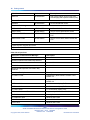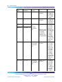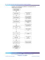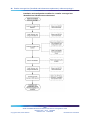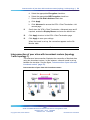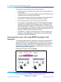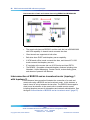
1
SMB
Small and Medium Business
Solutions Overview and
Configuration Guide
ATTENTION
Clicking on a PDF hyperlink takes you to the appropriate page. If necessary,
scroll up or down the page to see the beginning of the referenced section.
NN47910-200
.
Document status: Standard
Document version: 02.01
Document date: 11/22/2006
Copyright © 2006, Nortel Networks
All Rights Reserved.
The information in this document is subject to change without notice. The statements, configurations, technical
data, and recommendations in this document are believed to be accurate and reliable, but are presented without
express or implied warranty. Users must take full responsibility for their applications of any products specified in this
document. The information in this document is proprietary to Nortel Networks.
3
Contents
How to get help
5
New in this release
7
New products 7
Getting started
9
Overview 9
How to use this guide 9
First step 10
Second step 10
Third step 11
Preconfiguration checklist 12
New products 13
Business Ethernet Switches 13
Existing products 15
Business Element Manager 17
Business Access Point 120 (BAP120) 17
Business Secure Router 222 (BSR222) 18
Reference topologies and assumptions 18
IP addressing for SMB devices and DHCP 19
Installing the Element Manager 21
Converged small site (mixed-vendor environment): reference
topology 1
23
Configuring a converged small site (mixed-vendor environment)
24
Smaller converged site (Greenfield and infrastructure
replacement): reference topology 2
37
Configuring a smaller converged site (Greenfield and infrastructure
replacement) 38
Smaller remote site (Greenfield and infrastructure replacement):
reference topology 3
43
Configuring a smaller remote site (Greenfield and infrastructure replacement)
WAN interconnected LAN reference topologies
Configuring tunnels
44
49
50
SMB
Small and Medium Business Solutions Overview and Configuration Guide
NN47910-200 02.01 Standard
Release 1.00 11/22/2006
Copyright © 2006, Nortel Networks
.
Nortel Networks Confidential
4 Contents
Interconnection of peer sites with incumbent routers (topology 1 with topology
1) 53
Interconnection of peer sites using BSR222 (topology 2 with topology 2) 54
Interconnection of main and remote sites using BSR222 and BCM200/400
(topology 2 with BCM 200/400) 55
Interconnection of BSR222 and an incumbent router (topology 1 with topology
3) 56
Interconnection of main and remote sites using BSR222 (topology 2 with topology
3) 58
Maintenance
61
Security settings 61
Key factory security defaults 61
Securing your SMB network 62
BAP120 engineering rules and guidelines 65
Device quantities 65
BAP120 performance measurements 67
Third-party WiFi client interoperability 68
SMB
Small and Medium Business Solutions Overview and Configuration Guide
NN47910-200 02.01 Standard
Release 1.00 11/22/2006
Copyright © 2006, Nortel Networks
.
Nortel Networks Confidential
5
How to get help
This section explains how to get help for Nortel products and services.
Getting help from the Nortel Web site
The best way to get technical support for Nortel products is from the Nortel
Technical Support Web site:
www.nortel.com/support
This site provides quick access to software, documentation, bulletins, and
tools to address issues with Nortel products. More specifically, the site
enables you to:
•
download software, documentation, and product bulletins
•
search the Technical Support Web site and the Nortel Knowledge Base
for answers to technical issues
•
sign up for automatic notification of new software and documentation
for Nortel equipment
•
open and manage technical support cases
Getting help over the phone from a Nortel Solutions Center
If you do not find the information you require on the Nortel Technical Support
Web site, and have a Nortel support contract, you can also get help over the
phone from a Nortel Solutions Center.
In North America, call 1-800-4NORTEL (1-800-466-7835).
Outside North America, go to the following Web site to obtain the phone
number for your region:
www.nortel.com/callus
Getting help from a specialist by using an Express Routing Code
To access some Nortel Technical Solutions Centers, you can use an Express
Routing Code (ERC) to quickly route your call to a specialist in your Nortel
product or service. To locate the ERC for your product or service, go to:
SMB
Small and Medium Business Solutions Overview and Configuration Guide
NN47910-200 02.01 Standard
Release 1.00 11/22/2006
Copyright © 2006, Nortel Networks
.
Nortel Networks Confidential
6 How to get help
www.nortel.com/erc
Getting help through a Nortel distributor or reseller
If you purchased a service contract for your Nortel product from a distributor
or authorized reseller, contact the technical support staff for that distributor
or reseller.
SMB
Small and Medium Business Solutions Overview and Configuration Guide
NN47910-200 02.01 Standard
Release 1.00 11/22/2006
Copyright © 2006, Nortel Networks
.
Nortel Networks Confidential
7
New in this release
The following section details what is new in the Nortel Small and Medium
Business (SMB) Solutions Overview and Configuration Guide for SMB
(Small and Medium Business) portfolio Release 2.0.
New products
See the following sections for information about new products.
New products in this document
Product
Section
BES50 Series Ethernet switches
"New products " (page 13)
BES200 Series Ethernet switches
"New products " (page 13)
BES1000 Series Ethernet switches
"New products " (page 13)
SMB
Small and Medium Business Solutions Overview and Configuration Guide
NN47910-200 02.01 Standard
Release 1.00 11/22/2006
Copyright © 2006, Nortel Networks
.
Nortel Networks Confidential
8 New in this release
SMB
Small and Medium Business Solutions Overview and Configuration Guide
NN47910-200 02.01 Standard
Release 1.00 11/22/2006
Copyright © 2006, Nortel Networks
.
Nortel Networks Confidential
9
Getting started
Overview
This document provides the steps to configure three reference topologies
and their interconnections for the Small and Medium Business (SMB)
portfolio.
Use these example topologies only as a reference when you configure
your unique solution.
To reduce redundant documentation, reference the specific quick install
guides, configuration guides, and release notes.
Configuring each of the SMB reference topologies consists of individual
device configuration and solution-level configuration. All devices
(Business Secure Router [BSR222], Business Ethernet Switches [BES50,
BES100/200, BES1000], and Business Access Point [BAP120]) include a
Web interface to configure the device. The Element Manager provides a
centralized management application for launching these Web interfaces.
The Element Manager also provides integrated configuration panels for the
Business Communications Manager (BCM) and for the Business Ethernet
Switch (BES) devices.
The Business Element Manager (EM) provides a computer-based client
interface that can connect to devices over an IP network and display the
programming interface for that device. You can manage SMB devices using
the Web-based user interface that you launch from the Element Manager.
Through the Element Manager, you can configure necessary device
parameters and all the parameters for each of the reference topologies.
How to use this guide
Use this document to guide you through the steps that are required to
configure your site.
SMB
Small and Medium Business Solutions Overview and Configuration Guide
NN47910-200 02.01 Standard
Release 1.00 11/22/2006
Copyright © 2006, Nortel Networks
.
Nortel Networks Confidential
10 Getting started
First step
Assemble all tools and documentation required to configure your SMB
network. See "SMB Preconfiguration checklist" (page 12).
Second step
Determine which reference topologies and interconnected topologies most
closely resemble your unique solution.
Then read the following sections of this guide for more detail:
•
"New products" (page 13)
•
"Existing products" (page 15)
•
"Reference topologies and assumptions" (page 18)
The reference topologies do not represent a definitive solution for your
network but do offer detailed procedures that can provide a guideline for
your implementation.
•
"IP addressing for SMB devices and DHCP" (page 19)
•
"Installing the Business Element Manager" (page 21)
Stand-alone SMB sites
If your requirement is
•
solely for data connectivity with no requirement for voice solutions, then
configure your site based on the "Smaller converged site (Greenfield
and infrastructure replacement)—reference topology 2" (page 37).
•
IP or traditional telephony or both, and data connectivity, then configure
your site based on the "Smaller converged site (Greenfield and
infrastructure replacement)—reference topology 2" (page 37).
•
IP or traditional telephony or both, and data connectivity, and Guest
Access application service, then configure your site based on the
"Converged small site (mixed-vendor environment)—reference topology
1" (page 23).
Linked SMB sites
Linked SMB sites offer two main types of solutions:
•
IP trunk linked sites
•
main and remote linked sites
In IP trunk linked site scenarios, both sites have a BCM telephony call
server and hence are independent. An H.323 IP trunk links the sites for
harmonized private dialing plans through branch office virtual private
SMB
Small and Medium Business Solutions Overview and Configuration Guide
NN47910-200 02.01 Standard
Release 1.00 11/22/2006
Copyright © 2006, Nortel Networks
.
Nortel Networks Confidential
How to use this guide 11
network (VPN) tunnels. The linked SMB sites described in this guide are
verified for small deployment using BCM50 and larger deployment using
BCM200/400 in the following interconnected reference topologies:
•
"Interconnection of peer sites with incumbent routers (topology 1 with
topology 1)" (page 53)
•
"Interconnection of peer sites using BSR222 (topology 2 with topology
2)" (page 54)
•
"Interconnection of main and remote sites using BSR222 and
BCM200/400 (topology 2 with BCM 200/400)" (page 55)
In main and remote linked site scenarios, the main office hosts a BCM
telephony call server and is linked to remote offices where IP telephony
service is provided from the main office through branch office VPN
tunnels. Generally, these remote sites are very small offices where the
cost of deploying a locally hosted BCM telephony call server cannot be
justified. The linked SMB sites described in this guide are verified for small
deployment using BCM50 and larger deployment using BCM200/400 in the
following interconnected reference topologies:
•
"Interconnection of BSR222 and an incumbent router (topology 1 with
topology 3)" (page 56)
•
"Interconnection of main and remote sites using BSR222 (topology 2
with topology 3)" (page 58)
Third step
After you determine which topology you are configuring, proceed to the
associated section of this guide, as follows:
•
If you are configuring a smaller converged site—mixed vendor
environment, proceed to "Converged small site (mixed-vendor
environment)—reference topology 1" (page 23).
•
If you are configuring a smaller converged site—Greenfield and
infrastructure replacement, proceed to "Smaller converged site
(Greenfield and infrastructure replacement)—reference topology 2"
(page 37).
•
If you are configuring a smaller remote site—Greenfield and
infrastructure replacement, proceed to "Smaller remote site (Greenfield
and infrastructure replacement)—reference topology 3" (page 43).
•
If you are interconnecting multiple sites, proceed to "WAN interconnected
LAN reference topologies" (page 49).
SMB
Small and Medium Business Solutions Overview and Configuration Guide
NN47910-200 02.01 Standard
Release 1.00 11/22/2006
Copyright © 2006, Nortel Networks
.
Nortel Networks Confidential
12 Getting started
Preconfiguration checklist
The following table lists the production documentation that you need to
configure your network. Ensure you have all the applicable items prior to
configuring your SMB network.
Download the latest version from
www.nortel.com/support
SMB preconfiguration checklist
Document title
Check
BAP120 1.0
Quick Installation for the Nortel Business Access Point 120 (NN47921-300)
Using the Nortel Business Access Point 120 (NN47921-301)
Business Access Point 120 Release Notes (NN47921-400)
BES50 1.0
Quick Installation for the Nortel Business Ethernet Switch 50 Series
(NN47924-301)
Using the Nortel Business Ethernet Switch 50 Series (NN47924-300)
Business Ethernet Switch 50 Release Notes (NN47924-400)
BES100/200
Quick Installation for the Nortel Business Ethernet Switch 100/200 Series
(NN47925-301)
Using the Nortel Business Ethernet Switch 100/200 Series (NN47925-300)
Business Ethernet Switch 100/200 Release Notes (NN47925-400)
BES1000 1.0
Quick Installation for the Nortel Business Ethernet Switch 1000 Series
(NN47927-301)
Using the Nortel Business Ethernet Switch 1000 Series (NN47927-300)
BSR222
Quick Installation for the Nortel Business Secure Router 222 (NN47922-300)
Nortel Business Secure Router 222 Fundamentals (NN47922-301)
Nortel Business Secure Router 222 Configuration – Basics (NN47922-500)
Nortel Business Secure Router 222 Configuration – Advanced (NN47922-501)
Business Secure Router 222 Release Notes (NN47922-400)
BEM 1.0
Business Element Manager 1.0 Release Notes (NN47926-400)
BCM
SMB
Small and Medium Business Solutions Overview and Configuration Guide
NN47910-200 02.01 Standard
Release 1.00 11/22/2006
Copyright © 2006, Nortel Networks
.
Nortel Networks Confidential
New products 13
Document title
Check
Keycode Installation Guide (N40010-301)
BCM50 1.0
Networking Configuration Guide (N0027156)
First Time Installation and Configuration Guide (N0027149)
BCM50 2.0
Installation Checklist and Quick Start Guide (NN40020-308)
BCM 4.0
Networking Configuration Guide (N0060606)
Other
IP Telephony Client Deployment Technical Solutions Guide (January 2006)
New products
SMB portfolio 2.0 includes the following new products.
Model number
Description
Business Ethernet Switches
BES50FE-12T PWR
12 Port 10/100BASE-TX Fast Ethernet ports with PoE
BES50FE-24T PWR
24 Port 10/100BASE-TX Fast Ethernet ports with PoE
BES50GE-12 PWR
12 Port 10/100/1000BASE-T Gig Ethernet ports with PoE
BES50GE-24T PWR
24 Port 10/100/1000BASE-T Gig Ethernet ports with PoE
BES210-24T
24 Fast Ethernet ports, stackable
BES210-48T
48 Fast Ethernet ports, stackable
BES220-24T PWR
24 Fast Ethernet ports with PoE, stackable
BES220-48T PWR
48 Fast Ethernet ports with PoE, stackable
BES1010-24T
24 10/100/1000 autosensing ports with two shared SFP ports
BES1010-48T
48 10/100/1000 autosensing ports with two shared SFP ports
BES1020-24T PWR
24 10/100/1000 autosensing ports with two shared SFP ports
and PoE
BES1020-48T PWR
48 10/100/1000 autosensing ports with two shared SFP ports
and PoE
Business Ethernet Switches
The BES consist of three series:
•
BES50 series
•
BES100/200 series
SMB
Small and Medium Business Solutions Overview and Configuration Guide
NN47910-200 02.01 Standard
Release 1.00 11/22/2006
Copyright © 2006, Nortel Networks
.
Nortel Networks Confidential
14 Getting started
•
BES1000 series
BES50 series
The BES50 series is configurable with the BCM50 and other BES50s for
desktop or wall-mount installation.
•
BES50FE: The BES50FE-12T PWR offers 12 full-duplex
10/100BASE-TX Fast Ethernet ports, all of which support PoE, and the
BES50FE-24T PWR offers 24 full-duplex 10/100BASE-TX Fast Ethernet
ports, 12 of which support PoE.
•
BES50GE: The BES50GE-12T PWR offers 12 full-duplex
10/100/1000BASE-T Gigabit Ethernet ports, all of which support PoE,
and the BES50FE-24T PWR offers 24 full-duplex 10/100/1000BASE-T
Gig Ethernet ports, 12 of which support PoE.
•
Maximum power on any port is 15.4 Watts.
BES50 series switches are equipped with a dynamic host configuration
protocol (DHCP) client (configurable to BOOTP server or static IP address)
and support a Web management interface compatible with the Element
Manager (BEM).
BES100/200 series
The BES100/200 series is a family of 1U rack-mountable Ethernet switches
capable of supporting wire-speed connections on 24 or 48 Fast Ethernet
ports. These products can be either rack-mounted or physically stacked
on a bench.
•
BES110 (previously available in SMB portfolio release 1.0): The
BES110-24T offers 24 unpowered Fast Ethernet ports and the
BES110-48T offers 24 unpowered Fast Ethernet ports.
•
BES120 (previously available in SMB portfolio release 1.0): The
BES120-24T PWR offers 12 of 24 Fast Ethernet ports as powered ports
and the BES120-48T offers 24 of 48 Fast Ethernet ports as powered
ports.
•
BES210: The BES210-24T offers 24 unpowered Fast Ethernet ports
and the BES210-48T offers 48 unpowered Fast Ethernet ports.
•
BES220: The BES220-24T offers 12 of 24 Fast Ethernet ports as
powered ports and the BES220-48T offers 24 of 48 Fast Ethernet ports
as powered ports.
•
Maximum power on any port is 15.4 Watts.
•
All BES100/200 series switches are equipped with two 10/100/1000
Mb/s copper ports, a serial port, and SNMP and Web management
interfaces compatible with both the BEM and a simple Web browser.
SMB
Small and Medium Business Solutions Overview and Configuration Guide
NN47910-200 02.01 Standard
Release 1.00 11/22/2006
Copyright © 2006, Nortel Networks
.
Nortel Networks Confidential
Existing products 15
•
Up to four BES200 Series switches can be connected together using
stacking ports and accessed through a single Web user interface screen.
BOOTP is invoked at startup to obtain an IP address for the management
interface as the switches are not equipped with a host DHCP client. If the
solution provider wants to configure the management interface IP address
manually, they can power the BES without a DHCP/BOOTP server present
and browse to the factory default address for the management interface.
BES1000 series
The BES1000 series is a family of 1U rack-mountable Ethernet switches
supporting autosensing ports and small form factor pluggable (SFP) shared
gigabit interface converter (GBIC) slots.
•
BES1010: The BES1010-24T offers 24 10/100/1000 Mb/s autosensing
ports, including two shared SFP ports, and the BES1010-48T offers 48
10/100/1000 Mb/s autosensing ports, including two shared SFP ports.
•
BES1020: The BES 1020-24T PWR offers 24 10/100/1000 Mb/s
autosensing ports of which 12 are PoE ports, including two shared
SFP ports, and the BES 1020-48T PWR offers 48 10/100/1000 Mb/s
autosensing ports of which 24 are PoE ports, including two shared
SFP ports.
•
Maximum power on any port is 15.4 Watts.
•
All BES1000 series switches are equipped with a serial port and SNMP
and Web management interfaces compatible with both the BEM and a
simple Web browser.
BOOTP is invoked at startup to obtain an IP address for the management
interface as the switches are not equipped with a DHCP client. If the
solution provider wants to configure the management interface IP address
manually, they can power the BES without a DHCP/BOOTP server present
and browse to the factory default address for the management interface.
Existing products
The following existing Nortel products integrate with new SMB portfolio
release 2.0 products.
SMB Portfolio 1.0 products
Model number
Order code
Description
NT5S80AA
Element Manager
Element Manager
BEM1.0
Wireless LAN
SMB
Small and Medium Business Solutions Overview and Configuration Guide
NN47910-200 02.01 Standard
Release 1.00 11/22/2006
Copyright © 2006, Nortel Networks
.
Nortel Networks Confidential
16 Getting started
Model number
Order code
Description
BAP120
NT5S40CAE6
802.11a/b/g Indoor Access Point (AP)
with Bridging and Repeater Modes (PoE)
NT5S20AAE6
Secure Broadband Router
BES110-24T
NT5S01AEE5
24 Port 10/100 Rack Mount Switch
BES110-48T
NT5S01BEE5
48 Port 10/100 Rack Mount Switch
BES120-24T-PWR
NT5S01MEE5
24 Port 10/100 Rack Mount Switch with
PoE
BES120-48T-PWR
NT5S01NEE5
48 Port 10/100 Rack Mount Switch with
PoE
Secure Router
BSR222
Ethernet Switching
Accessories
Optional power supplies and cords
Optional Antennas for BAP120
Other Nortel products
Business Communications Manager
Description
BCM50
release 1.0
BCM50 Expansion and Media Bay Modules
BCM400
release 4.0
BCM200
release 4.0
BCM200/400 Expansion and Media Bay
Modules
Landline IP telephones
Description
IP Phone 1120E
Supported by BCM software release 4 and
BCM50 2.0
IP Phone 1140E
Supported by BCM software release 4 and
BCM50 2.0
IP Phone 2001
3 x 24 character display, PoE
IP Phone 2002
4 x 24 character display, PoE
IP Phone 2004
8 x 24 character display, PoE
IP Audio Conference Phone 2033
Supported by BCM 4.0 and BCM50 2.0
Soft clients
Description
IP Softphone 2050
Windows Soft Client
Mobile Voice Client 2050
Pocket PC Soft Client
VPN Client
Windows Soft Client
SMB
Small and Medium Business Solutions Overview and Configuration Guide
NN47910-200 02.01 Standard
Release 1.00 11/22/2006
Copyright © 2006, Nortel Networks
.
Nortel Networks Confidential
Existing products 17
Accessories
Description
Mobile USB Headset Adaptor for IP soft phones
For soft clients
IP Phone Key Expansion Module
For 2000 series telephones
Business Element Manager
The Business Element Manager is a Windows application that integrates
a Windows-like navigation panel with a simple network management
protocol (SNMP)-based discovery mechanism and various means of
product configuration depending on what features are supported by the
target product.
The Element Manager enables streamlined access to BES devices,
BAP120, and the BSR222 Web management screens. It also enables the
BES series management interface to support and access active content
such as port statistics measurement. These interfaces appear in the
Element Manager client window when you double-click the respective
devices from the Element Manager navigation panel.
A Web management interface also exists for the BCM50 and BCM200/400,
making seamless management of a converged SMB network possible.
Element Manager software can reside on any local area network
(LAN)-connected PC and be launched when required. Alternatively, a
remote PC running the Element Manager client located anywhere on the
Internet can securely manage devices on a target LAN through the BSR222
and VPN soft client.
The Element Manager is not required to manage individual products. You
can manage each product independently through its Web management
interface. The Element Manager simplifies access to multiple products and
enables active content where available.
Business Access Point 120 (BAP120)
The BAP120 is an IEEE 802.11a, 802.11b/g-compatible product that
provides transparent, wireless high-speed data communications between
the wired LAN and fixed or mobile devices equipped with either an 802.11a
or 802.11 b/g wireless adapter, or both. Any number of BAP120 products
can operate together in a network. This product can sit on a desktop or
mount inconspicuously on a wall or ceiling. The BAP120 is equipped with
a serial port, SNMP, and Web management interfaces compatible with the
Element Manager.
SMB
Small and Medium Business Solutions Overview and Configuration Guide
NN47910-200 02.01 Standard
Release 1.00 11/22/2006
Copyright © 2006, Nortel Networks
.
Nortel Networks Confidential
18 Getting started
Business Secure Router 222 (BSR222)
The BSR222 is a two-port router with a Cat5 wide area network (WAN)
connection and four 10/100 Mb/s LAN ports. It has roughly one-fourth the
footprint of a BCM50 and is powered by a local power adaptor through a
barrel plug. The router provides WAN connectivity to one or more Ethernet
switches and to the necessary client and branch tunnels to enable secure
remote access. The BSR222 is equipped with a serial port, SNMP, and Web
management interfaces compatible with the Element Manager.
Reference topologies and assumptions
This section outlines the assumptions for the reference topologies described
in this guide.
Small and medium-sized businesses typically use a third-party cable or
asymmetric digital subscriber line (ADSL) modem for high-speed Internet
access. The ISP must be able to provide a single static IP address to each
site. The BSR222 uses network address translation (NAT) to a private
IP address space and provides a firewall between the resultant private
LAN and the Internet. An internal DHCP server faces the private LAN.
All connected network equipment (BCM, BAP120, and BES) obtains the
associated IP address using DHCP from the router DHCP server.
Personal computers (PC), personal digital assistants (PDA), laptops, and
Nortel IP phones obtain private IP addresses from the same DHCP server.
Voice support is provided with Nortel IP phones, Voice Soft-Clients, and the
BCM communications server. IP phones receive IP addresses from the
BSR222. However, in a topology where a third-party router is present, IP
phones receive IP addresses from the BCM.
Nortel IP phones and soft phones run a proprietary stimulus protocol that
is terminated at the BCM. The BCM presents H.323 trunks to other sites
encapsulated inside VPN branch tunnels that are established between
pairs of sites. The BCM also mediates control and voice flows destined
for the local public switched telephone network (PSTN). A Nortel 2050
Voice Soft-Client runs on an IEEE 802.11e EDCA WMM-compatible
notebook computer or PDA connected by a wireless local area network
(WLAN) (BAP120). A second voice soft client (the Nortel MVC 2050)
tailored for a PDA also connects through a standard 802.11b WLAN. The
BAP120 supports IEEE 802.11e Quality of Service (QoS) tagging (for
example, EDCA/WMM interim QoS for multimedia) and traffic segregation
(SSID-to-VLAN mapping) for enhanced voice quality and security. Roaming,
such as handoff of data connections between access points, is supported.
The BSR222 performs secure routing functions and supports a combination
of 10 client and branch tunnels. The BCM50, Business Ethernet Switches,
BAP120, and BSR222 are all manageable using the Element Manager
application.
SMB
Small and Medium Business Solutions Overview and Configuration Guide
NN47910-200 02.01 Standard
Release 1.00 11/22/2006
Copyright © 2006, Nortel Networks
.
Nortel Networks Confidential
IP addressing for SMB devices and DHCP 19
All reference topologies assume that each device on the subnet has its
SNMP client enabled.
IP addressing for SMB devices and DHCP
Nortel recommends using DHCP to obtain IP addresses for SMB devices
and end nodes (such as PCs and IP phones).
The SMB reference topologies 2 and 3 rely on a DHCP server running on
the BSR222 in the subnet (typically occupying address 192.168.1.1). SMB
reference topology 1 relies on a DHCP server running on a third-party router.
DHCP serves IP addresses dynamically to all devices and end nodes
connected to the subnet. As devices are connected to the subnet, they
take IP addresses from the DHCP pool from 192.168.1.2 to 192.168.1.127
inclusive.
If DHCP is not running on the subnet, all SMB devices are shipped with
factory-default IP addresses that exist within ranges of the subnet that
minimize IP address conflict.
The following table lists the default IP addresses, valid IP ranges, and
default DHCP status for all SMB devices.
IP addressing for SMB devices and DHCP
Device
type
Default IP
address
IP address
range
DHCP/BOOTP
Notes
BSR222
192.168.1.1
None
DHCP server
enabled.
IP address
pool starting
address =
192.168.1.2,
pool size = 126.
This is
the default
gateway.
This is
the DHCP
server.
Pool size is
currently set
at 126.
BCM50 1.0
192.168.1.2
None
DHCP client
enabled
Only one
BCM50 rec
ommended
in an SMB
network.
BCM50 2.0
192.168.1.2
None
DHCP client
enabled
Only one
BCM50 rec
ommended
in an SMB
network.
SMB
Small and Medium Business Solutions Overview and Configuration Guide
NN47910-200 02.01 Standard
Release 1.00 11/22/2006
Copyright © 2006, Nortel Networks
.
Nortel Networks Confidential
20 Getting started
Device
type
Default IP
address
IP address
range
DHCP/BOOTP
Notes
BCM 4.0
192.168.1.2
None
DHCP client
enabled
Only one
BCM50 rec
ommended
in an SMB
network.
BES50
192.168.1.12
8
None
DHCP client
enabled
Also suppo
rts BOOTP
and static IP
addressing.
BES100/2
00
192.168.1.13
2
BES1000
192.168.1.13
2
192.168.1.1
32
through
192.168.1.1
35
BOOTP mode
set to BOOTP
or default
IP (BOOTP
timeout is set
at 60 seconds)
If DHCP is
not used
and more
than one
BES device
is deployed,
you must
manually
configure
the addre
sses to be
consecutive
within this
range.
BAP120
192.168.1.13
6
192.168.1.1
36 through
192.168.1.1
51
DHCP client
enabled
If DHCP is
not used
and more
than one
BAP120 is
deployed,
you must
manually
configure
the addre
sses to be
consecutive
within this
range.
IP Phones
192.168.1.15
2
192.168.1.1
52 through
192.168.1.2
54
DHCP client
enabled
If DHCP is
not used
and more
than one
IP Phone
is deployed,
you must
manually
configure
SMB
Small and Medium Business Solutions Overview and Configuration Guide
NN47910-200 02.01 Standard
Release 1.00 11/22/2006
Copyright © 2006, Nortel Networks
.
Nortel Networks Confidential
Installing the Element Manager
Device
type
Default IP
address
IP address
range
DHCP/BOOTP
21
Notes
the addre
sses to be
consecutive
within this
range.
Installing the Element Manager
The Element Manager 1.0 supports all SMB data products (BSR222,
BES50/100/200/1000, and BAP120) as well as BCM50 1.0 and 2.0, and
BCM 4.0. However, the BCM Element Manager does not support SMB
devices.
ATTENTION
The Element Manager 1.0 must be installed on your computer if you want to
manage both SMB data products and existing BCM devices.
Prerequisites
The following items are required before you can install the Element Manager.
•
System requirements:
— Windows: Windows 98 SE™, Windows 2000™, Windows XP™
— RAM: minimum 256 MB, recommended 512 MB
— Free space: 150 MB
•
Element Manager software downloaded from
www.nortel.com/support.
Procedure steps
Step
Action
1
Double-click the Element Manager Installer icon and click Run.
2
In the Install Wizard
a. Read through the Introduction page and click Next.
b. Read through the License Agreement page and click Next.
c. Choose the install folder and click Next.
d. Click On the Desktop to choose the shortcut folder.
e. Review the Pre-Installation Summary and click Install.
—End—
SMB
Small and Medium Business Solutions Overview and Configuration Guide
NN47910-200 02.01 Standard
Release 1.00 11/22/2006
Copyright © 2006, Nortel Networks
.
Nortel Networks Confidential
22 Getting started
SMB
Small and Medium Business Solutions Overview and Configuration Guide
NN47910-200 02.01 Standard
Release 1.00 11/22/2006
Copyright © 2006, Nortel Networks
.
Nortel Networks Confidential
23
Converged small site (mixed-vendor
environment): reference topology 1
The converged small site (mixed-vendor environment)—reference topology
1 consists of a third-party router providing routing capabilities with one
or more Business Ethernet Switches. Each Business Ethernet Switch
(BES) provides traditional and Power over Ethernet (PoE) port-expansion
capabilities to accommodate up to 48 node devices. A maximum of four
Business Access Point (BAP120) devices can be connected to each BES to
provide wireless access capability to node devices on the subnet. A local
BCM50 supplies telephony support. See the figure Converged small site
(mixed-vendor environment).
This reference topology
•
uses the dynamic host configuration protocol (DHCP) server on the
third-party router to serve IP addresses to the BES100/200, BCM50,
and BAP120 devices as they are connected
•
uses the DHCP server on the BCM50 to serve IP addresses to IP
phones running on laptops and personal digital assistants (PDA)
•
illustrates a fully managed and converged Nortel subsystem for a mixed
environment
•
provides virtual local area network (VLAN) traffic segregation and Guest
Access support on an incumbent router compliant to the parameters
listed in "Installing and configuring the third-party router" (page 28)
This guide describes how to enable VLAN and Guest Access support on an
incumbent router included in this reference topology.
The BCM50 1.0 enables enhanced telephony features including Auto
Attendant, Unified Messaging, Contact Center, custom dialing plans, and
dozens of powerful call features.
The Guest Access application enables the SMB business site to offer
high-speed Internet access to visiting customers. This application uses
a WiFi BAP120 communication infrastructure to isolate external traffic
SMB
Small and Medium Business Solutions Overview and Configuration Guide
NN47910-200 02.01 Standard
Release 1.00 11/22/2006
Copyright © 2006, Nortel Networks
.
Nortel Networks Confidential
24 Converged small site (mixed-vendor environment): reference topology 1
from the private SMB subnets using access control list (ACL) rules that
are configured on the third-party router. A dedicated VLAN 2 for Guest
Access traffic is mapped to a dedicated service set identifier (SSID) on the
BAP120. The result is a high-performance Internet-access courtesy service
for individuals visiting SMB-configured sites that is secure and completely
isolated from mission-critical SMB private networks.
Converged small site (mixed-vendor environment)
Configuring a converged small site (mixed-vendor environment)
This section details the steps required to connect, install, and configure a
converged small site (mixed-vendor environment). For details see
•
"Connecting network devices for a converged small site (mixed-vendor
environment)" (page 25)
SMB
Small and Medium Business Solutions Overview and Configuration Guide
NN47910-200 02.01 Standard
Release 1.00 11/22/2006
Copyright © 2006, Nortel Networks
.
Nortel Networks Confidential
Configuring a converged small site (mixed-vendor environment)
•
25
"Installation and configuration workflow for a converged small site
(mixed-vendor environment)" (page 26)
The installation sequence is a critical component of this minimal
configuration scenario. Nortel recommends that you wait a few minutes
between configuring and installing each device to allow each device to
complete the boot cycle.
Connecting network devices for a converged small site (mixed-vendor
environment)
Step
Action
1
Connect the WAN port of the third-party router to the Internet
provider.
2
Connect the BES100/200 to the LAN port on the third-party router.
3
Connect the BCM50 to one of the VLAN 1 LAN ports on the
BES100/200.
4
Connect BAP120s to PoE ports on the BES100/200 if PoE ports are
available. If not, connect BAP120s to LAN ports on the BES100/200.
5
If Guest Access is required, connect the BAP120s that supply
wireless Guest Access to one or more of the ports designated to
VLAN 2 (guest) on the BES100/200.
—End—
SMB
Small and Medium Business Solutions Overview and Configuration Guide
NN47910-200 02.01 Standard
Release 1.00 11/22/2006
Copyright © 2006, Nortel Networks
.
Nortel Networks Confidential
26 Converged small site (mixed-vendor environment): reference topology 1
Installation and configuration workflow for a converged small site
(mixed-vendor environment)
SMB
Small and Medium Business Solutions Overview and Configuration Guide
NN47910-200 02.01 Standard
Release 1.00 11/22/2006
Copyright © 2006, Nortel Networks
.
Nortel Networks Confidential
Autodiscovering and configuring SMB devices to support the converged small site (mixed vendor
environment) (topology 1) 27
Autodiscovering and configuring SMB devices to support the
converged small site (mixed vendor environment) (topology 1)
This reference topology uses the DHCP server on the third-party router
to serve IP addresses to the BES100/200, BCM50, and BAP120 devices
as they are connected. The IP phones receive their IP address from the
BCM50 server set to IP phones only. The installation sequence is a critical
component of this minimal configuration scenario.
The "Topology 1: Network connectivity diagram" (page 27) illustrates an
implementation example of topology 1 using two VLANs. VLAN 1 has data,
voice, and operations, administration and maintenance (OAM) while VLAN
2 is used for Guest Access.
Topology 1: Network connectivity diagram
SMB
Small and Medium Business Solutions Overview and Configuration Guide
NN47910-200 02.01 Standard
Release 1.00 11/22/2006
Copyright © 2006, Nortel Networks
.
Nortel Networks Confidential
28 Converged small site (mixed-vendor environment): reference topology 1
In this example, two port-based VLANs are established on the BES100/200.
VLAN 1 is the default VLAN with a port membership of 1 through 10 and 12
through 50, leaving port 11 out of the VLAN. VLAN 2 is also a port-based
VLAN with port membership of 1, 2, and 11. VLAN 2 allows ports 1 and 2 to
be members of the guest and default management VLANs, but keeps port
11 separated as a wired port dedicated to the guest VLAN only.
This reference topology describes a simple example; however, port selection
for VLANs must reflect the specific needs of the installation.
Installing and configuring the third-party router
Step
Action
1
Install the third-party router, referring to the manufacturer’s
documentation and procedures.
2
Set the following parameters on the third-party router:
a. support of network address translation (NAT)
b. support of the static routing function
c. support of four at a minimum, but preferably eight LAN-based
routings for each physical port
d. support of VPN gateway static and dynamic tunnels (IPSec data
encryption standard (DES) and 3DES encryption)
e. support of multiscope DHCP server function: four subnets at a
minimum, but preferably eight
f.
3
support of Stateful firewall functions
Configure the NAT IP address translation by using the many-to-one
port-based method.
ATTENTION
For the Voice VLAN, two DHCP servers exist: one on the third-party
router and one on the BCM50. You must configure the IP address pools
for each of these DHCP servers so that IP addresses for the third-party
router are not duplicated in the BCM50 IP address range and vice versa.
4
Configure the third-party router DHCP server with mapping of subnet
to VLAN-tagged traffic as follows:
a. DHCP server pool-1 = 192.168.1.2 to 192.168.1.127, mask
255.255.255.0, default gateway 192.168.1.1
b. DHCP server pool-2 = 192.168.2.2 to 192.168.2.127, mask
255.255.255.0, default gateway 192.168.2.1
SMB
Small and Medium Business Solutions Overview and Configuration Guide
NN47910-200 02.01 Standard
Release 1.00 11/22/2006
Copyright © 2006, Nortel Networks
.
Nortel Networks Confidential
Autodiscovering and configuring SMB devices to support the converged small site (mixed vendor
environment) (topology 1) 29
c. Routing subnet1 (192.168.1.x/255.255.255.0, gateway
192.168.1.1) maps to VLAN 1
d. Routing subnet2 (192.168.2.x/255.255.255.0, gateway
192.168.2.1) maps to VLAN 2
5
Configure the Guest Access application (access control list [ACL])
as follows:
a. Configure the third-party router to isolate the VLAN 2-tagged
traffic (for example, the 192.168.2.x pool of addresses) from
the SMB private network (for example, the 192.168.1.x pool of
addresses).
b. Use the ACL feature to deny the 192.168.2.x subnet to access
and route to the 192.168.1.x pool of IP addresses, and to enable
the 192.168.2.x to route through the firewall/NAT to access the
Internet.
—End—
Installing the Element Manager
Step
Action
1
Install the Element Manager software on a local PC.
2
Launch the Element Manager application.
—End—
Installing and discovering the BES100/200
Step
Action
1
Install and power up the BES100/200. For details, see the Business
Ethernet Switch 100/200 Series Quick Install Guide.
2
Connect the management PC to one of the BES100/200 RJ-45 ports.
3
In the Element Manager, Element Navigation Panel, click Network >
Find Network Element > Business Ethernet Switch.
The Network Device Search dialog box appears.
4
Select the default IP address range.
5
Click OK.
The device is added to the Element Navigation Panel.
SMB
Small and Medium Business Solutions Overview and Configuration Guide
NN47910-200 02.01 Standard
Release 1.00 11/22/2006
Copyright © 2006, Nortel Networks
.
Nortel Networks Confidential
30 Converged small site (mixed-vendor environment): reference topology 1
—End—
Configuring the VLANs on the BES100/200
Step
Action
1
In the Element Manager, Element Navigation Panel, select the
BES100/200, and either click Web Page on the toolbar, or right-click
the BES100/200 and then click Web Page.
2
On the BES100/200 Web UI, select Application > VLAN > VLAN
Configuration to access the VLAN table.
The default VLAN 1 port is listed.
3
Click Create VLAN.
The VLAN Configuration: Port based page appears.
4
Type the VLAN number (2), and optionally, a VLAN name, and then
click Submit.
VLAN 2 is added to the VLAN table.
5
To configure VLAN 1
a. Click the Action button for VLAN 1, located on the left of the
VLAN table.
The VLAN—Port Based Setting table appears for VLAN 1.
b. Clear the port 11 Port Membership check box.
c. Click Submit.
6
To configure the VLAN trunking on the BES100/200:
a. Click Application > VLAN > Port Configuration to access the
VLAN Port Setting table.
b. From the Egress Tagging list, select ON for port 1 and port 2.
7
To configure VLAN 2:
a. Click Application > VLAN > VLAN Configuration to access
the VLAN table.
b. Click the Action button for VLAN 2.
The VLAN – Port Based Setting table appears for VLAN 2.
c. Select the 1, 2, and 11 Port Membership check boxes.
d. Click Submit.
SMB
Small and Medium Business Solutions Overview and Configuration Guide
NN47910-200 02.01 Standard
Release 1.00 11/22/2006
Copyright © 2006, Nortel Networks
.
Nortel Networks Confidential
Autodiscovering and configuring SMB devices to support the converged small site (mixed vendor
environment) (topology 1) 31
—End—
Installing and discovering the BAP120
Step
Action
1
Install and power up the BAP120. For details, see the Business
Access Point 120 Quick Install Guide.
2
Connect the BAP120 to one of the VLAN 1 ports on the BES100/200.
For this example, use port 3.
3
In the Element Manager, Element Navigation Panel, click Network >
Find Network Element > Business Ethernet Switch.
The Network Device Search dialog box appears.
4
Select the default IP address range.
5
Click OK.
The device is added to the Element Navigation Panel.
—End—
Configuring the BAP120
Step
Action
1
In the Element Manager, Element Navigation Panel, select the
BAP120, and either click Web Page on the toolbar, or right-click the
BAP120 and then click Web Page.
2
To set the default VLAN ID on BAP120—802.11a radio
a. Click Configuration > SLOT 0 – Radio A > Radio Settings to
access the Default VLAN ID (1~4094) table.
b. Enter the following individual settings for the VLAN IDs:
i.
VAP0—1
ii. VAP1—2
iii. VAP3—1
iv. VAP4—1
c. Click Submit.
3
To enable Guest Access SSID on BAP120 – 802.11a radio
SMB
Small and Medium Business Solutions Overview and Configuration Guide
NN47910-200 02.01 Standard
Release 1.00 11/22/2006
Copyright © 2006, Nortel Networks
.
Nortel Networks Confidential
32 Converged small site (mixed-vendor environment): reference topology 1
a. Click Configuration > SLOT 0 – Radio A > Security.
b. Select the Enable check boxes for VAP0 and VAP1.
c. Click Submit.
4
To set the default VLAN ID on BAP120—802.11b/g radio
a. Click Configuration > SLOT 1 – Radio G > Radio Settings to
access the Default VLAN ID (1~4094) table.
b. Enter the following individual settings for the VLAN IDs:
i.
VAP0—1
ii. VAP1—2
iii. VAP3—1
iv. VAP4—1
c. Click Submit.
5
To enable Guest Access SSID on BAP120 – 802.11b/g radio
a. Click Configuration > SLOT 1 – Radio G > Security.
b. Select the Enable check boxes for VAP0 and VAP1.
c. Click Submit.
6
To enable the VLAN on BAP120
a. Click System > VLAN to access the VLAN Configuration table.
b. For the VLAN Classification, select Enable.
c. Enter 1 as the Native VLAN ID.
d. Click Submit.
A confirmation dialog box appears, asking you to confirm
changes and informing you that you may lose connectivity to
the BAP120.
e. In the confirmation dialog box, click OK, and then wait for
approximately 30 seconds before you proceed.
7
Disconnect the BAP120 from the VLAN #3 port, and then connect it
to one of the VLAN 2 ports on the BES100/200. For this example,
use port 2.
—End—
SMB
Small and Medium Business Solutions Overview and Configuration Guide
NN47910-200 02.01 Standard
Release 1.00 11/22/2006
Copyright © 2006, Nortel Networks
.
Nortel Networks Confidential
Autodiscovering and configuring SMB devices to support the converged small site (mixed vendor
environment) (topology 1) 33
Installing the BCM50
Step
Action
1
Install and power up the BCM50. For details, see the BCM50 First
Time Installation and Configuration Guide.
2
Obtain and apply the necessary keycodes to enable the required
BCM features. For details see the BCM50 Keycode Installation
Guide.
3
Connect the BCM50 (LAN port) to a VLAN 1 port on the BES. For
this example, use port 4.
4
In the Element Manager, Element Navigation Panel, click Network >
Find Network Element > Business Ethernet Switch.
The Network Device Search dialog box appears.
5
Select the default IP address range.
Because the DHCP client on the BCM50 is active, the BCM50 gets
the next available IP address from the third-party router. For this
example, the IP address is 192.168.1.19.
6
Click OK.
The device is added to the Element Navigation Panel.
—End—
Configuring the BCM50
Step
Action
1
In the Element Manager, Element Navigation Panel, select the
BCM50 and either click Connect on the toolbar, or right-click the
BCM50 and then click Connect.
2
In the Task Navigation Panel, click the Configuration tab.
3
Click Data Services > DHCP Server to access the DHCP Server
window.
ATTENTION
For the Voice VLAN, two DHCP servers exist—one on the third-party
router and one on the BCM50. You must configure the IP address pools
for each of these DHCP servers so that IP addresses for the third-party
router are not duplicated in the BCM50 IP address range and vice versa.
SMB
Small and Medium Business Solutions Overview and Configuration Guide
NN47910-200 02.01 Standard
Release 1.00 11/22/2006
Copyright © 2006, Nortel Networks
.
Nortel Networks Confidential
34 Converged small site (mixed-vendor environment): reference topology 1
4
From the DHCP server is list, select Enabled—IP Phones Only.
5
In the Task Navigation Panel, click the Configuration tab, and
click Resources > Telephony Resources to access the Telephony
Resources window.
6
Click the IP Terminal Global Settings tab.
7
Select the check boxes for Enable registration, Enable global
registration password, and Auto-assign DN.
ATTENTION
Because Enable global registration password is selected, a password is
requested when the IP phones register with the BCM50. The default
password is BCMI.
8
Leave the remaining default values.
—End—
Connecting the IP phones
Nortel IP phones are fully DHCP-enabled, and require no setup. Each IP
Phone receives a DHCP address from the BCM50. After the IP Phones are
connected to the BCM50, the details appear in the IP Terminal Details tab in
the Telephony Resources window.
Procedure steps
Step
Action
1
Connect the Ethernet port of the IP Phone to a VLAN 1 port on the
BES. For this example, two IP 2004 phones are connected to the
PoE ports.
2
In the Element Manager, Element Navigation Panel, click
Configuration > Telephony Resources > IP Terminal Details to
view the settings.
—End—
SMB
Small and Medium Business Solutions Overview and Configuration Guide
NN47910-200 02.01 Standard
Release 1.00 11/22/2006
Copyright © 2006, Nortel Networks
.
Nortel Networks Confidential
Summary of topology 1 35
Summary of topology 1
Using the preceding configuration example, wireless Guest Access is
enabled on port 2 using VLAN 2, and single dedicated wired Guest Access
is enabled on port 11 of the BES100/200. A typical Guest-Access scenario
follows:
1. A wireless Guest Access user associates their laptop wireless client
card to SSID vlan2-dot11bg.
2. The wireless client DHCP client requests an IP address from the DHCP
server on the third-party router. The DHCP request flows through
SSID vlan2-dot11bg and is mapped by the BAP120 onto VLAN 2. Port
2 has VLAN trunking enabled and passes the tagged frame on the
BES100/200, which broadcasts the frame to the entire VLAN 2 domain.
3. The third-party router connected on port 1 sees all VLAN traffic. The
router provides a response to the wireless client DHCP request on
the VLAN 2 domain and allocates an IP address from the 192.168.2.x
DHCP server pool.
4. Because the entire 192.168.2.x subnet is configured with ACL on the
third-party router, it can access only the Internet and, hence, is totally
isolated from the other private subnet (192.168.1.x).
SMB
Small and Medium Business Solutions Overview and Configuration Guide
NN47910-200 02.01 Standard
Release 1.00 11/22/2006
Copyright © 2006, Nortel Networks
.
Nortel Networks Confidential
36 Converged small site (mixed-vendor environment): reference topology 1
SMB
Small and Medium Business Solutions Overview and Configuration Guide
NN47910-200 02.01 Standard
Release 1.00 11/22/2006
Copyright © 2006, Nortel Networks
.
Nortel Networks Confidential
37
Smaller converged site (Greenfield and
infrastructure replacement): reference
topology 2
The smaller converged site (Greenfield and infrastructure replacement)
reference topology 2 enables secure converged telephony and Internet
access. This topology consists of a Business Secure Router (BSR) 222
providing routing capabilities with one or more Business Ethernet Switches.
Each Business Ethernet Switch (BES) provides traditional and Power over
Ethernet (PoE) port-expansion capabilities to accommodate up to 48 node
devices. A maximum of four Business Access Point (BAP120) devices can
be connected to each BES to provide wireless access capability to node
devices on the subnet. A local BCM50 supplies telephony support. See the
figure "Smaller converged site (Greenfield and infrastructure replacement)"
(page 38).
This reference topology
•
assumes that dynamic host configuration protocol (DHCP) is running
on the BSR222 internal router to provide IP addressing to devices
connected to the subnet
•
illustrates an example that applies to Greenfield deployment and
infrastructure replacement
The Element Manager 1.0 enables discovery and configuration of connected
devices.
The BCM50 1.0 enables enhanced telephony features including Auto
Attendant, Unified Messaging, Contact Center, custom dialing plans, and
dozens of powerful call features.
SMB
Small and Medium Business Solutions Overview and Configuration Guide
NN47910-200 02.01 Standard
Release 1.00 11/22/2006
Copyright © 2006, Nortel Networks
.
Nortel Networks Confidential
38 Smaller converged site (Greenfield and infrastructure replacement): reference topology 2
Smaller converged site (Greenfield and infrastructure replacement)
Configuring a smaller converged site (Greenfield and infrastructure
replacement)
This section details the steps required to connect, install, and configure a
smaller converged site (Greenfield and infrastructure replacement). For
details see:
•
"Connecting network devices for a Smaller converged site (Greenfield
and infrastructure replacement)" (page 39)
•
"Installation and configuration workflow for a Smaller converged site
(Greenfield and infrastructure " (page 40)
SMB
Small and Medium Business Solutions Overview and Configuration Guide
NN47910-200 02.01 Standard
Release 1.00 11/22/2006
Copyright © 2006, Nortel Networks
.
Nortel Networks Confidential
Configuring a smaller converged site (Greenfield and infrastructure replacement)
39
The installation sequence is a critical component of this minimal
configuration scenario. Nortel recommends that you wait a few minutes
between configuring and installing each device to allow each device to
complete the boot cycle.
Connecting network devices for a smaller converged site (Greenfield
and infrastructure replacement)
Step
Action
1
Connect the network devices as follows:
a. Connect the WAN port of the BSR222 to the Internet provider.
b. Connect the BES100/200 to the LAN port on the BSR222.
c. Connect the BCM50 to one of the LAN ports on the BES100/200.
d. Connect BAP120s to PoE ports on the BES100/200 if PoE ports
are available. If not, connect the BAP120s to LAN ports on the
BES100/200.
—End—
SMB
Small and Medium Business Solutions Overview and Configuration Guide
NN47910-200 02.01 Standard
Release 1.00 11/22/2006
Copyright © 2006, Nortel Networks
.
Nortel Networks Confidential
40 Smaller converged site (Greenfield and infrastructure replacement): reference topology 2
Installation and configuration workflow for a smaller converged site
(Greenfield and infrastructure replacement)
SMB
Small and Medium Business Solutions Overview and Configuration Guide
NN47910-200 02.01 Standard
Release 1.00 11/22/2006
Copyright © 2006, Nortel Networks
.
Nortel Networks Confidential
Configuring a smaller converged site (Greenfield and infrastructure replacement)
41
Discovering the BCM50
Step
Action
1
Start the Element Manager.
2
In the Element Manager, Element Navigation Panel, right-click the
Network Element folder.
3
Click Network > Find Network Element > Business
Communication Manager.
The Network Device Search dialog box appears.
4
Check the starting and ending IP addresses.
a. If the IP addresses match those of your subnet, click OK.
b. If the IP addresses do not match, change the IP addresses to
match your subnet and then click OK.
5
Enter your user ID and password.
6
Click OK.
The device is added to the Element Navigation Panel.
—End—
The installation and configuration of the network devices in the smaller
converged site (Greenfield and infrastructure replacement)—reference
topology 2 is complete. You can now connect network element nodes such
as PCs, IP phones, wireless laptops, and personal digital assistants (PDAs)
to the BES100/200 and BAP120 switches. The DHCP server on the BSR222
serves IP addresses dynamically to these devices as they are connected.
SMB
Small and Medium Business Solutions Overview and Configuration Guide
NN47910-200 02.01 Standard
Release 1.00 11/22/2006
Copyright © 2006, Nortel Networks
.
Nortel Networks Confidential
42 Smaller converged site (Greenfield and infrastructure replacement): reference topology 2
SMB
Small and Medium Business Solutions Overview and Configuration Guide
NN47910-200 02.01 Standard
Release 1.00 11/22/2006
Copyright © 2006, Nortel Networks
.
Nortel Networks Confidential
43
Smaller remote site (Greenfield and
infrastructure replacement): reference
topology 3
The smaller remote site (Greenfield and infrastructure replacement)
reference topology 3 enables secure converged telephony and Internet
access for very small deployments. This topology allows the site to be
served with telephony by a larger site that is linked through a branch
office VPN tunnel. This topology consists of a BSR222 providing routing
capabilities with one or more Business Ethernet Switches. Each Business
Ethernet Switch (BES) provides traditional and Power over Ethernet (PoE)
port-expansion capabilities to accommodate up to 48 node devices. You
can connect a maximum of four BAP120 devices to each BES to provide
wireless access capability to node devices on the subnet. A remote BCM50,
BCM200, or BCM400 supplies telephony support. See the figure "Smaller
remote site (Greenfield and infrastructure replacement)" (page 44).
This reference topology
•
assumes that DHCP is running on the BSR222 to provide IP addressing
to the BES100/200 and BAP120 devices connected to the subnet
•
illustrates an example that applies to Greenfield deployment and
infrastructure replacement
The Element Manager 1.0 enables discovery and configuration of connected
devices.
A remote BCM 50/200/400 enables enhanced telephony features including
Auto Attendant, Unified Messaging, Contact Center, custom dialing plans,
and dozens of powerful call features.
SMB
Small and Medium Business Solutions Overview and Configuration Guide
NN47910-200 02.01 Standard
Release 1.00 11/22/2006
Copyright © 2006, Nortel Networks
.
Nortel Networks Confidential
44 Smaller remote site (Greenfield and infrastructure replacement): reference topology 3
Smaller remote site (Greenfield and infrastructure replacement)
Configuring a smaller remote site (Greenfield and infrastructure
replacement)
This section details the steps required to connect, install and configure a
smaller remote site (Greenfield and infrastructure replacement). For details
see
•
"Connecting network devices for a Smaller remote site (Greenfield and
infrastructure replacement)" (page 45)
•
"Installation and configuration workflow for a Smaller remote site
(Greenfield and infrastructure rep" (page 46)
SMB
Small and Medium Business Solutions Overview and Configuration Guide
NN47910-200 02.01 Standard
Release 1.00 11/22/2006
Copyright © 2006, Nortel Networks
.
Nortel Networks Confidential
Configuring a smaller remote site (Greenfield and infrastructure replacement)
45
The installation sequence is a critical component of this minimal
configuration scenario. Nortel recommends that you wait a few minutes
between configuring and installing each device to allow each device to
complete the boot cycle.
Connecting network devices for a smaller remote site (Greenfield and
infrastructure replacement)
Step
Action
1
Connect the network devices as follows:
a. Connect the WAN port of the BSR222 to the Internet provider.
b. Connect the BES100/200s to the LAN ports on the BSR222.
c. Connect BAP120s to PoE ports on the BES100/200 if PoE ports
are available. If not, connect BAP120s to LAN ports on the
BES100/200.
—End—
SMB
Small and Medium Business Solutions Overview and Configuration Guide
NN47910-200 02.01 Standard
Release 1.00 11/22/2006
Copyright © 2006, Nortel Networks
.
Nortel Networks Confidential
46 Smaller remote site (Greenfield and infrastructure replacement): reference topology 3
Installation and configuration workflow for a smaller remote site (Greenfield
and infrastructure replacement)
Setting up the BSR222 to supply S1 and S2 information to the IP Phones
As this is a remote site, use a command line interface (CLI) command to
manually set the S1 and S2 addresses pointing to the BCM at the main site.
Prerequisites
•
Telnet or secure shell (SSH) must be enabled on the router.
Setting up the BSR222 to supply S1 and S2 information to the IP sets
Step
Action
1
Connect to the router through Telnet or SSH.
SMB
Small and Medium Business Solutions Overview and Configuration Guide
NN47910-200 02.01 Standard
Release 1.00 11/22/2006
Copyright © 2006, Nortel Networks
.
Nortel Networks Confidential
Configuring a smaller remote site (Greenfield and infrastructure replacement)
2
47
Select menu 24, select menu 8, and enter the following commands:
a. ip dhcp enif0 server voipserver 1 <BCM50_IP_Address > 7000 1
b. ip dhcp enif0 server voipserver 2 <BCM50_IP_Address> 7000 1
3
Add the IP phones configured for full DHCP client mode to the
remote site.
—End—
The installation and configuration of the network devices in the smaller
remote site (Greenfield and infrastructure replacement)—reference topology
3 is complete. You can now connect network element nodes such as
PCs, IP phones, wireless laptops, and PDAs to the BES100/200 and
BAP120 switches. The DHCP server on the BSR222 serves IP addresses
dynamically to these devices as they are connected.
SMB
Small and Medium Business Solutions Overview and Configuration Guide
NN47910-200 02.01 Standard
Release 1.00 11/22/2006
Copyright © 2006, Nortel Networks
.
Nortel Networks Confidential
48 Smaller remote site (Greenfield and infrastructure replacement): reference topology 3
SMB
Small and Medium Business Solutions Overview and Configuration Guide
NN47910-200 02.01 Standard
Release 1.00 11/22/2006
Copyright © 2006, Nortel Networks
.
Nortel Networks Confidential
49
WAN interconnected LAN reference
topologies
This section describes possible interconnection scenarios of the reference
topologies described earlier in the guide. These scenarios are produced by
combining the different reference topologies as end points on the branch
tunnel. The sequence for interconnecting the reference topologies is
essentially the same:
•
Configure each remote or converged site.
•
Configure the required branch tunnels.
•
Configure the required client tunnels.
This section describes the following reference interconnected topologies:
•
"Interconnection of peer sites with incumbent routers (topology 1 with
topology 1)" (page 53)
•
"Interconnection of peer sites using BSR222 (topology 2 with topology
2)" (page 54)
•
"Interconnection of main and remote sites using BSR222 and
BCM200/400 (topology 2 with BCM 200/400)" (page 55)
•
"Interconnection of BSR222 and an incumbent router (topology 1 with
topology 3)" (page 56)
•
"Interconnection of main and remote sites using BSR222 (topology 2
with topology 3)" (page 58)
SMB
Small and Medium Business Solutions Overview and Configuration Guide
NN47910-200 02.01 Standard
Release 1.00 11/22/2006
Copyright © 2006, Nortel Networks
.
Nortel Networks Confidential
50 WAN interconnected LAN reference topologies
Configuring tunnels
After the sites are configured, configure the branch and client tunnels as
required by the site. See the figures "Branch tunnel configuration diagram"
(page 50) and "Client tunnel configuration diagram" (page 51).
Branch tunnel configuration diagram
Configuring a branch tunnel
Step
Action
1
Start the Element Manager, and access the BSR222 Web page.
2
In the Element Manager, Element Navigation Panel, click VPN to
access the VPN page and click the Summary tab.
3
From the Contivity VPN Client list, select an open item.
4
Click Edit to access the VPN—Branch Office page.
5
On the VPN—Branch Office page
a. Select Branch Office as the connection type.
b. Select the Active check box and the Nailed Up check box.
c. Type a name for the tunnel.
d. Type the key that was previously shared and retype to confirm.
ATTENTION
This key must be identical at both ends of the tunnel.
e. Type the secure gateway address for the far end of the tunnel.
6
Click Add to save the settings and access the VPN—Branch
Office—IP Policy page.
SMB
Small and Medium Business Solutions Overview and Configuration Guide
NN47910-200 02.01 Standard
Release 1.00 11/22/2006
Copyright © 2006, Nortel Networks
.
Nortel Networks Confidential
Configuring tunnels
7
51
On the VPN—Branch Office—IP Policy page
a. In the Address type, Starting IP address, Ending IP
address/subnet mask, and Port fields, type the required
information for the local site.
b. In the Address type, Starting IP address, Ending IP
address/subnet mask, and Port fields, type the required
information for the remote site.
8
Click Apply to save the settings and return to the VPN—Branch
Office page.
9
On the VPN Branch Office page, click the down arrows to move the
new policy into the Select IP Policy list.
10
In the navigation pane, choose VPN to access the VPN page.
11
Click the SA Monitor tab.
12
On the VPN—SA Monitor page, ping the far-end LAN IP address of
the router or another known network device.
When the tunnel is set up, the connection appears on the SA
Monitor table.
—End—
Client tunnel configuration diagram
SMB
Small and Medium Business Solutions Overview and Configuration Guide
NN47910-200 02.01 Standard
Release 1.00 11/22/2006
Copyright © 2006, Nortel Networks
.
Nortel Networks Confidential
52 WAN interconnected LAN reference topologies
Configuring a client tunnel
Step
Action
1
Start the Element Manager, and access the BSR222 Web page.
2
In the Element Manager, Element Navigation Panel, click VPN >
Client Termination .
3
Click the Local User Database link to access the Local User
Database page.
4
Scroll to the bottom of the page.
5
Click Edit to access the User Edit page.
6
On the User Edit page
a. Select the Active check box.
b. In the User Type box, select IPSec.
c. Type the user name and password, and retype to confirm the
password.
d. Type an account name.
e. In the Remote User—Static IP Address box, type an unused IP
address that is from a different network than the LAN interface.
You are essentially creating a new network for the VPN users.
f.
In the Static Subnet Mask box, type 255.255.255.255.
ATTENTION
If you do not enter this value in the Static Subnet Mask field an invalid IP
address error results.
g. Click Apply.
7
Repeat steps 1 - 6 to add more users. Remember to increment the
static IP address when you add new users.
8
In the navigation pane, click VPN to access the VPN page. and .
9
Click the Client Termination tab.
10
On the Client Termination page:
a. Select the Enable Client Terminationcheck box.
b. Select the Local User Databasecheck box.
c. Select the User Name and Password/Pre-Shared Key check
box.
SMB
Small and Medium Business Solutions Overview and Configuration Guide
NN47910-200 02.01 Standard
Release 1.00 11/22/2006
Copyright © 2006, Nortel Networks
.
Nortel Networks Confidential
Interconnection of peer sites with incumbent routers (topology 1 with topology 1)
53
d. Select the appropriate Encryption check box.
e. Select the appropriate IKE Encryption check box.
f.
Select the Use Static Address check box.
g. Click Apply.
h. Click Advanced to access the VPN—Client Termination—Advanced page.
11
Scroll down the VPN—Client Termination—Advanced page and if
required, enable the Display Banner and enter the banner text.
12
Click Apply to return to the VPN—Client Termination page.
13
Click Apply to save your settings.
When the tunnel is set up, the connection appears on the SA
Monitor table.
—End—
Interconnection of peer sites with incumbent routers (topology
1 with topology 1)
This reference interconnection illustrates the connection of identical sites
using two incumbent routers. In this instance, a branch tunnel is set up
between the two sites. See the figure, "Interconnection of peer sites with
incumbent routers" (page 53).
Interconnection of peer sites with incumbent routers
SMB
Small and Medium Business Solutions Overview and Configuration Guide
NN47910-200 02.01 Standard
Release 1.00 11/22/2006
Copyright © 2006, Nortel Networks
.
Nortel Networks Confidential
54 WAN interconnected LAN reference topologies
This reference interconnection has the following features:
•
Two identical sites, each with an incumbent router, are connected by a
branch tunnel.
•
A dedicated host control protocol (DHCP) server is the incumbent router.
A telephony server is located in the BCM50.
•
A virtual private network (VPN) branch office tunnel connects the sites,
and internal IP H.323 trunks connect the telephony servers.
•
IP terminals at each site use H.323 trunks and local PSTN.
•
The incumbent router enables partition of VLAN-mapped SSID traffic
from BAP120 and BES100/200 to multiple subnets. Multipool DHCP
enables separate voice, data, and Guest Access on a common local
area network (LAN). The ability of the incumbent router to manage wide
area network (WAN) egress and assert DiffServ differentiated services
code point (DSCP) further enhances the solution.
•
The BCM50 1.0 enables enhanced telephony features including Auto
Attendant, Unified Messaging, Contact Center, custom dialing plans,
and dozens of powerful call features.
Interconnection of peer sites using BSR222 (topology 2 with
topology 2)
This reference interconnection illustrates the connection of identical sites
using two BSR222 devices. In this instance, a branch tunnel is set up
between the two sites. The BSR222 also supports client tunnel termination
at either site to enable remote access, including telephony access for
teleworkers and network administrators. See the figure "Interconnection of
peer sites using BSR222" (page 54).
Interconnection of peer sites using BSR222
SMB
Small and Medium Business Solutions Overview and Configuration Guide
NN47910-200 02.01 Standard
Release 1.00 11/22/2006
Copyright © 2006, Nortel Networks
.
Nortel Networks Confidential
Interconnection of main and remote sites using BSR222 and BCM200/400 (topology 2 with BCM
200/400) 55
This reference interconnection has the following features:
•
Each site has a BSR222 and BCM50. A branch tunnel connects the
sites, and the BCM50 acts as a gateway to each site.
•
Ten VPN tunnels are supported by each BSR for use by teleworkers
or network administrators.
•
The BSR222 or BCM50 provides a DHCP at each site.
•
A telephony server for each site is located in the BCM50.
•
The BCM50 1.0 enables enhanced telephony features including Auto
Attendant, Unified Messaging, Contact Center, custom dialing plans,
and dozens of powerful call features.
Interconnecting peer sites using BSR222
Step
Action
1
At each site
a. Ensure that the DHCP server in the BCM50 is disabled, that the
BCM50 is connected to the router, and that both boot.
b. Add the IP phones to the site as described in the BCM50 First
Time Installation and Configuration Guide.
2
Create a branch tunnel between the sites. See "Configuring a
branch tunnel" (page 50).
3
Create an H.323 trunk between the BCM50s, as described in the
BCM50 First Time Installation and Configuration Guide.
—End—
Interconnection of main and remote sites using BSR222 and
BCM200/400 (topology 2 with BCM 200/400)
This reference interconnection illustrates the connection of a main and
remote site using a BSR222 and a BCM200 or BCM400 with VPN
capability. In this instance, a branch tunnel is set up between the two sites.
In this example, the BCM50 and the BCM200 or BCM400 are networked
using H.323 trunks in much the same way as time division multiplexing
(TDM) private branch exchanges (PBX) use tie trunks. See the figure
"Interconnection of main and remote sites using BSR222 and BCM200/400"
(page 56).
SMB
Small and Medium Business Solutions Overview and Configuration Guide
NN47910-200 02.01 Standard
Release 1.00 11/22/2006
Copyright © 2006, Nortel Networks
.
Nortel Networks Confidential
56 WAN interconnected LAN reference topologies
Interconnection of main and remote sites using BSR222 and BCM200/400
This reference interconnection has the following features:
•
The remote site has one BSR222, and the main site has a BCM200/400
with VPN capability. A branch tunnel connects the sites.
•
Client tunnels are supported at both sites.
•
Both sites have DHCP and telephony server capability.
•
A VPN branch office tunnel connects the sites, and internal IP H.323
trunks connect the telephony servers.
•
IP terminals at the remote site use H.323 trunks and local PSTN.
•
The BCM50 1.0 enables enhanced telephony features including Auto
Attendant, Unified Messaging, Contact Center, custom dialing plans,
and dozens of powerful call features.
Interconnection of BSR222 and an incumbent router (topology 1
with topology 3)
This reference interconnection illustrates the connection of a main and
remote site using a BSR222 and an incumbent router. In this instance, a
branch tunnel is set up between the two sites. The BSR222 also supports
client tunnel termination at the remote site to enable remote access,
including telephony access for teleworkers and network administrators. See
the figure "Interconnection of BSR222 and an incumbent router" (page 57).
SMB
Small and Medium Business Solutions Overview and Configuration Guide
NN47910-200 02.01 Standard
Release 1.00 11/22/2006
Copyright © 2006, Nortel Networks
.
Nortel Networks Confidential
Interconnection of BSR222 and an incumbent router (topology 1 with topology 3)
57
Interconnection of BSR222 and an incumbent router
This reference interconnection has the following features:
•
The remote site has a BSR222, and the main site has an incumbent
router. A branch tunnel connects the sites.
•
The VPN branch office tunnel is on a separate IP subnet.
•
Ten VPN tunnels are supported by the BSR222 at the remote site for
use by teleworkers or network administrators.
•
A DHCP server is the incumbent router. A telephony server is located
in the BCM50.
•
An incumbent router enables partition of VLAN-mapped SSID traffic
from BAP120 and BES100/200 to multiple subnets. Multipool DHCP
enables separate voice, data, and Guest Access on a common LAN.
The ability of the incumbent router to manage WAN egress and assert
DiffServ DSCP further enhances the solution.
•
IP terminals at the remote site are extensions of the BCM50 at the main
site. There is no remote gateway and no dial tone if WLAN connection
drops.
•
The BCM50 1.0 enables enhanced telephony features including Auto
Attendant, Unified Messaging, Contact Center, custom dialing plans,
and dozens of powerful call features.
SMB
Small and Medium Business Solutions Overview and Configuration Guide
NN47910-200 02.01 Standard
Release 1.00 11/22/2006
Copyright © 2006, Nortel Networks
.
Nortel Networks Confidential
58 WAN interconnected LAN reference topologies
Interconnection of main and remote sites using BSR222 (topology
2 with topology 3)
This reference interconnection illustrates the connection of a main and
remote site using two BSR222 devices. In this instance, a branch tunnel
is set up between the two sites, and a client tunnel is configured at either
site to enable remote access, including telephony access for teleworkers
and network administrators. See the figure "Interconnection of main and
remote sites using BSR222" (page 58).
Interconnection of main and remote sites using BSR222
This reference interconnection has the following features:
•
Each site has a BSR222. A branch tunnel connects the sites.
•
Ten VPN tunnels are supported by each BSR222 for use by teleworkers
or network administrators.
•
A DHCP is provided by the BSR222 at each site.
•
A telephony server (BCM50) is located on the main site (topology 2).
•
The BCM50 1.0 enables enhanced telephony features including Auto
Attendant, Unified Messaging, Call Center, custom dialing plans, and
dozens of powerful call features.
•
IP terminals at the remote site are extensions of the BCM at the main
site.
Interconnecting main and remote sites using BSR222
Step
Action
1
In the main site, ensure that the DHCP server in the BCM50 is
disabled, that the BCM50 is connected to the router, and that both
boot.
SMB
Small and Medium Business Solutions Overview and Configuration Guide
NN47910-200 02.01 Standard
Release 1.00 11/22/2006
Copyright © 2006, Nortel Networks
.
Nortel Networks Confidential
Interconnection of main and remote sites using BSR222 (topology 2 with topology 3)
59
2
In the remote site, using a CLI command, set the S1 and S2
addresses to the IP address of the BCM50, identified in the router
DHCP table or in the BCM50.
3
Connect to the router through Telnet or SSH. (Telnet or SSH must
be enabled on that router.) Select menu 24, select menu 8, and
enter the following commands:
a. ip dhcp enif0 server voipserver 1 <BCM50_IP_Address > 7000 1
b. ip dhcp enif0 server voipserver 2 <BCM50_IP_Address> 7000 1
4
Add the IP phones to the main site as described in the BCM50 First
Time Installation and Configuration Guide.
5
Create a client tunnel to the remote site. See "Configuring a client
tunnel" (page 52).
—End—
SMB
Small and Medium Business Solutions Overview and Configuration Guide
NN47910-200 02.01 Standard
Release 1.00 11/22/2006
Copyright © 2006, Nortel Networks
.
Nortel Networks Confidential
60 WAN interconnected LAN reference topologies
SMB
Small and Medium Business Solutions Overview and Configuration Guide
NN47910-200 02.01 Standard
Release 1.00 11/22/2006
Copyright © 2006, Nortel Networks
.
Nortel Networks Confidential
61
Maintenance
Security settings
This section details the following guidelines for improving the security on
your network:
•
"Key factory security defaults" (page 61)
•
"Securing your SMB network" (page 62)
Key factory security defaults
The following tables list the key factory security defaults for each device.
These defaults are intended to bring consistency to the SMB portfolio by
allowing a near-zero configuration upon network deployment.
SMB device factory security defaults
Device
Web UI
user ID
Web UI
password
SNMP read
community
string
SNMP read
community
string
Web UI
inactivity
timeout
BAP120
nnadmin
PlsChgMe!
PlsChgMe!RO
PlsChgMe!RW
1 minute
BES50
nnadmin
PlsChgMe!
PlsChgMe!RO
PlsChgMe!RW
1 minute
BES100/200
nnadmin
PlsChgMe!
PlsChgMe!RO
PlsChgMe!RW
1 minute
BES1000
nnadmin
PlsChgMe!
PlsChgMe!RO
PlsChgMe!RW
1 minute
BSR222
nnadmin
PlsChgMe!
PlsChgMe!RO
PlsChgMe!RW
5 minutes
SMB
Small and Medium Business Solutions Overview and Configuration Guide
NN47910-200 02.01 Standard
Release 1.00 11/22/2006
Copyright © 2006, Nortel Networks
.
Nortel Networks Confidential
62 Maintenance
The Element Manager uses the default SNMP read/write community strings
as listed in the following table to discover devices. Because the SMB
devices and the Element Manager are using the same values, discovery
occurs upon network deployment.
Default SNMP read/write community strings
Application
SNMP read community
string
SNMP read community
string
Element Manager
PlsChgMe!RO
PlsChgMe!RW
If you change the simple network management protocol (SNMP) read/write
community strings, make the corresponding changes to the Element
Manager.
Saving SNMP read/write community strings
Step
Action
1
In the Element Manager, Element Navigation Panel, click View >
Preferences.
The Preferences dialog box appears.
2
Click the Network Elements tab.
3
Select the Store network element passwords check box.
4
Click OK.
—End—
A Web user interface session times out after the designated value of time
passes. For the BSR222, this value is 5 minutes. For the BES and the
BAP120 devices, the timeout value is 1 minute. You can change these
timeout values through the Web user interface for each device.
Securing your SMB network
The SMB factory security defaults described in "Key factory security
defaults" (page 61) allow for ease of installation and efficient network
deployment.
Nortel recommends that you change the factory default user IDs and that
you change passwords frequently using strong password methodology.
If you have a security policy in place that prevents the use of network
management protocols such as SNMP, follow the guidelines in this section
to establish your network without SNMP.
SMB
Small and Medium Business Solutions Overview and Configuration Guide
NN47910-200 02.01 Standard
Release 1.00 11/22/2006
Copyright © 2006, Nortel Networks
.
Nortel Networks Confidential
Securing your SMB network
63
The Element Manager is available as an SNMP-based network management
tool in the following cases:
•
Discovery of SNMP-based SMB data devices (BSR222, BES, BAP120)
is completed using SNMP.
•
Validation and addition of SNMP-based SMB data devices (BSR222,
BES, BAP120) on the network element tree is completed using SNMP.
•
Configuration of a BES device using the connect feature of the Element
Manager is completed using SNMP.
If you are deploying your SMB data network without SNMP, you cannot use
the Element Manager for device-configuration purposes. In these cases,
use a Web browser to manage each device.
Note that IP addresses for each device may not be apparent because they
are allocated by the DHCP server during deployment.
Discovering IP addresses in non-SNMP data networks
Step
Action
1
Disable SNMP on all devices.
2
Disable a BES50/100/200/1000 (BES) using the BES Web UI:
a. From the Web UI navigation panel located in the left-hand pane,
click Configuration > SNMP > Agent statusRemote Access
to access the Agent Status Settings table.
b. Clear the Enable check box.
c. Click Submit.
3
Disable the BAP120 using the BAP120 Web UI:
a. From the Web UI navigation panel located in the left-pane, click
Configuration > System > SNMP to access the SNMP system
page.
b. Select Disable.
c. Click Submit.
4
Disable the BSR222 using the BSR222 Web UI:
a. From the Web UI main menu, click Remote Management and
click the SNMP tab.
b. From the Service Access pane select Disable.
c. Click Apply.
SMB
Small and Medium Business Solutions Overview and Configuration Guide
NN47910-200 02.01 Standard
Release 1.00 11/22/2006
Copyright © 2006, Nortel Networks
.
Nortel Networks Confidential
64 Maintenance
5
Use your Web browser bookmark feature to save a shortcut to each
device.
6
Use the BSR222 Web UI to note all the IP addresses that have been
provided to your SMB network as follows:
a. From the Web UI navigation panel located in the left-hand pane,
click Maintenance.
b. Click the DHCP Table tab.
A listing of all IP addresses that the DHCP server allocated
appears.
You can access all SMB devices through a Web browser using
the IP addresses obtained from the previous step. You can use
your Web browser bookmark feature to save a shortcut to each
device.
—End—
Deploying SMB networks without using DHCP
The SMB data solution uses a DHCP server running on the BSR222
to serve IP addresses to BAP120 and BES50/100/200/1000 devices
using the DHCP client. This technique provides a near-zero configuration
deployment. However, you can use the following steps to deploy SMB data
devices without DHCP.
Procedure steps
Step
Action
1
On the BSR222 Web UI main menu, click LAN.
2
Click the IP tab.
3
From the DHCP list, select None.
4
Click Apply to save the changes.
This action disables the dynamic host configuration protocol (DHCP)
server function on the BSR222.
5
Reboot the BES100/200/1000 (BES).
The BES tries unsuccessfully to obtain an IP address from the
DHCP server on the BSR222. After 60 seconds, it defaults to an IP
address of 192.168.1.132 (192.168.1.128 for BES50).
6
Reboot the BAP120.
SMB
Small and Medium Business Solutions Overview and Configuration Guide
NN47910-200 02.01 Standard
Release 1.00 11/22/2006
Copyright © 2006, Nortel Networks
.
Nortel Networks Confidential
BAP120 engineering rules and guidelines
65
The BAP120 tries unsuccessfully to obtain an IP address from the
DHCP server on the BSR222. After 60 seconds, it defaults to an IP
address of 192.168.1.136.
—End—
If you have more than one BES or BAP120 in your SMB network, IP
addresses must be manually configured according to the ranges specified
in the "IP addressing for SMB devices and DHCP" (page 19) table.
BAP120 engineering rules and guidelines
This section provides engineering guidelines to assist you in determining
equipment requirements, placement devices, and third-party wireless fidelity
(WiFi) compatibility for the BAP120.
Device quantities
The following three tables provide engineering guidelines around the
number of PoE devices that can be supported on a given SMB site,
depending on the equipment requirements.
The SMB devices such as IP phones and BAP120s use PoE powering
method for ease of cabling, hence avoiding the requirement for multiple
ac/dc power adapters. BES devices offer 12-port and 24-port PoE versions.
These tables also account for the number of BAP120 devices deployed to
a given site. Based on product engineering limits, the tables offer a quick
method of determining equipment quantity requirements for IP phones, WiFi
clients, and other legacy phone equipment that is supported for a given
SMB equipment deployment scenario.
More IP phones for each BAP120 device can be deployed if you use
AC/DC power adapters to connect equipment to BES non-PoE ports. The
BAP120 also supports Wireless Bridging. Wireless bridging can be used
to reduce the requirement for wired ports from BES devices and allows
you to daisy-chain access points wirelessly. For engineering rules for such
deployments, contact Nortel technical support.
Port count and device support table
Available ports
Non-PoE
PoE
Uplink
BAP units
BES devices, 48 ports, 24 with PoE
1
24
24
1
0
1
24
24
1
1
1
24
24
1
2
SMB
Small and Medium Business Solutions Overview and Configuration Guide
NN47910-200 02.01 Standard
Release 1.00 11/22/2006
Copyright © 2006, Nortel Networks
.
Nortel Networks Confidential
66 Maintenance
Available ports
Non-PoE
PoE
Uplink
BAP units
1
24
24
1
3
1
24
24
1
4
BES devices, 24 ports, 12 with PoE
1
12
12
1
0
1
12
12
1
1
1
12
12
1
2
1
12
12
1
3
1
12
12
1
4
BAP120
Associated
clients per
AP
BCM50
Active #
clients per
AP
IP clients
limit
TDM phones
(expansion
module)
Analog
phones
BES devices, 48 ports, 24 with PoE
1
32
20
32
44
4
1
32
20
32
44
4
1
32
20
32
44
4
1
32
20
32
44
4
1
32
20
32
44
4
BES devices, 24 ports, 12 with PoE
1
32
20
32
44
4
1
32
20
32
44
4
1
32
20
32
44
4
1
32
20
32
44
4
1
32
20
32
44
4
Wireline
2xxx IP
phones
Wireless
soft
phones
Wireless
data
clients
TDM
phones
Analog
phones
Total
BES devices, 48 ports, 24 with PoE
1
23
0
0
44
4
71
1
21
2
30
44
4
101
1
20
4
60
44
4
132
1
19
6
90
44
4
163
1
18
8
120
44
4
194
SMB
Small and Medium Business Solutions Overview and Configuration Guide
NN47910-200 02.01 Standard
Release 1.00 11/22/2006
Copyright © 2006, Nortel Networks
.
Nortel Networks Confidential
BAP120 engineering rules and guidelines
Wireline
2xxx IP
phones
Wireless
soft
phones
Wireless
data
clients
TDM
phones
Analog
phones
Total
67
BES devices, 24 ports, 12 with PoE
1
11
0
0
44
4
59
1
9
2
30
44
4
89
1
8
4
60
44
4
120
1
7
6
90
44
4
151
1
6
8
120
44
4
182
BAP120 performance measurements
The following two tables illustrate the typical range and throughput
measurements for the BAP120. Measurements were tested in real-life
indoor office environments.
Use the data in these tables when determining the placement for your
BAP120 devices to provide the optimum balance between range and
throughput desired performance level for your site. To provide optimum
roaming performance, place your BAP120 devices so that there is
approximately 30 percent radio coverage overlap.
BAP120 performance range measurements table
BAP120 measured range
802.11a radio
802.11b/g
Indoor open space
Physical data rate
51 meters
54 Mb/s
56 meters
48 Mb/s
68 meters
36 Mb/s
80 meters
24 Mb/s
60 meters
54 Mb/s
68 meters
48 Mb/s
80 meters
36 Mb/s
SMB
Small and Medium Business Solutions Overview and Configuration Guide
NN47910-200 02.01 Standard
Release 1.00 11/22/2006
Copyright © 2006, Nortel Networks
.
Nortel Networks Confidential
68 Maintenance
BAP120 measured range
Indoor open space
Physical data rate
Range measurements depend on regulatory domain radio-output settings and radio frequency (RF)
environment conditions at the moment of measurements.
Greater distances may be achieved at lower physical data rates.
BAP120 performance measured throughput table
802.11a radio
802.11g radio
802.11b radio
Measured
throughput
Distances
User throughput
(TCP)
maximum
8 meters
22 Mb/s
typical
46 meters
17 Mb/s
maximum
8 meters
22 Mb/s
typical
46 meters
17 Mb/s
maximum
8 meters
5.8 Mb/s
typical
46 meters
5.2 Mb/s
All throughput measurements are performed using transmission control protocol (TCP).
Different (likely higher) throughput can be observed using user datagram protocol (UDP).
Third-party WiFi client interoperability
The BAP120 is a WiFi-certified access point (WPA/WPA2 Enterprise and
WiFi multimedia (WMM) certified). This means that the BAP120 passes a
set of interoperability compliance tests. The WiFi-compliance test suite
involves interoperability testing evidence with a finite list of third-party
vendor WiFi client devices.
Nortel has augmented this interoperability testing coverage with a longer
list of vendors. The following table lists third-party WiFi clients, beyond
the standard list used for testing, that have shown successful functional
interoperability results.
Third-party WiFi client listing
Vendor name
Product
name
Model
Compatibility
Atheros
Atheros
AR5002X
+ Universal
802.11a/b/g
Wireless
Network
Adapter
AR5BSB-000
35A
11 a/b/g
Form
factor
Driver
revision
9.0.0.0.91
SMB
Small and Medium Business Solutions Overview and Configuration Guide
NN47910-200 02.01 Standard
Release 1.00 11/22/2006
Copyright © 2006, Nortel Networks
.
Nortel Networks Confidential
BAP120 engineering rules and guidelines
Vendor name
Product
name
Broadcom
Broadcom
802.11abg
CardBus
Reference
Design BCM9430
9CB
Intel
Intel PRO
/Wireless
2915 ABG
Mini-PCI
Adapter
Realtek
RTL8185&8
255
Proxim
ORiNOCO
11a/b/g
ComboCard
Gold - World
Cisco
Cisco
Aironet
802.11a/b/g
Wireless
CardBus
Adapter
Nortel Networks
WLAN Mob
ile Adapter
2202
SMC
Model
Compatibility
Form
factor
69
Driver
revision
4.10.36.0
WM3B2915A
BGNA
11 a/b/g
mini-PCI
9.0.3.9
5.101.804.20
04
11 b/g
CardBus
3.1.2.19
11 a/b/g
CardBus
2.0.0.27
WLAN 2202
11 a/b/g
(Super AG)
CardBus
3.0.0.0
EZ-Stream
Universal
Wireless
Cardbus
Adapter
SMC2336WAG
11 a/b/g
(Super AG)
CardBus
2.4.1.32
Netgear
RangeMAX
Wireless PCI
Adapter
WPN311
11 b/g
(Super AG)
PCI
4.0.0.167
Netgear
802.11a/b/g
Dual Band
Wireless PC
Card
WG511U
11 a/b/g
(Super AG
with XR)
CardBus
Netgear
108 Mb/s
Wireless PC
Card
WG511T
11 b/g
(Super G)
CardBus
8480-WD
3.3.0.156
SMB
Small and Medium Business Solutions Overview and Configuration Guide
NN47910-200 02.01 Standard
Release 1.00 11/22/2006
Copyright © 2006, Nortel Networks
.
Nortel Networks Confidential
70 Maintenance
Vendor name
Product
name
Model
Compatibility
Form
factor
Driver
revision
Netgear
108 Mb/s
Wireless PCI
Adapter
WG311T
11 b/g
(Super AG)
PCI
4.0.0.167
TRENDware
108 Mb/s
802.11a/g
Wireless
USB 2.0
Adapter
TEW-504UB
11 a/b/g
(Super AG)
USB
1.1.0.25
TRENDware
108 Mb/s
802.11g
MIMO
Wireless PC
Card
TEW-601PC
11 b/g
(Super G with
XR)
CardBus
1.1.0.22
TRENDware
108 Mb/s
802.11a/g
Wireless PCI
Adapter
TEW-503PI
11 a/b/g
(Super AG)
PCI
4.1.2.56
USRobotics
Wireless
MAXg PC
Card
USR5411
11 b/g
CardBus
3.100.46.5
Belkin
Wireless G
Notebook
Card
F5D7010
11 b/g
CardBus
4.1.2.56
Belkin
Wireless
G Plus
Notebook
Card
F5D7011
11 b/g
CardBus
3.100.64.0
Buffalo
54 Mb/s
Wireless
Notebook
Adapter
WLI-CB-G54
11 b/g
CardBus
3.30.15.1
Microsoft
Broadband
Networking
Wireless
Notebook
Adapter
MN-720
11 b/g
CardBus
3.20.26.0
Dell
TrueMobile
TrueMobile
1450
11 a/b/g
mini-PCI
4.10.40.0
SMB
Small and Medium Business Solutions Overview and Configuration Guide
NN47910-200 02.01 Standard
Release 1.00 11/22/2006
Copyright © 2006, Nortel Networks
.
Nortel Networks Confidential
SMB
Small and Medium Business Solutions Overview and
Configuration Guide
Copyright © 2006, Nortel Networks
All Rights Reserved.
Publication: NN47910-200
Document status: Standard
Document version: 02.01
Document date: 11/22/2006