1
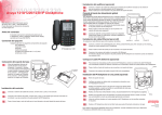
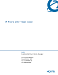
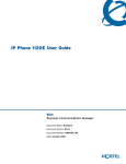
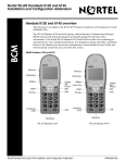
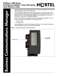
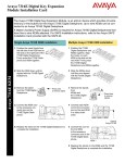
IP Key Expansion Module (KEM) User Guide
BCM
Business Communications Manager
Document Status: Standard
Document Version: 03.01
Document Number: NN40050-103
Date: November 2006
Copyright © Nortel Networks Limited 2006, All rights reserved.
The information in this document is subject to change without notice. The statements, configurations, technical data, and
recommendations in this document are believed to be accurate and reliable, but are presented without express or implied
warranty. Users must take full responsibility for their applications of any products specified in this document. The
information in this document is proprietary to Nortel Networks.
Trademarks
Nortel, the Nortel logo, and the Globemark are trademarks of Nortel Networks.
Microsoft, MS, MS-DOS, Windows, and Windows NT are registered trademarks of Microsoft Corporation.
All other trademarks and registered trademarks are the property of their respective owners.
3
About the Key Expansion Module (KEM)
This document describes the Nortel IP Phone Key Expansion Module (KEM) and how to use it
with the Nortel IP Phone 2002 and Nortel IP Phone 2004.
Description
The IP Phone KEM is a hardware component that connects to the IP Phone 2002 and IP Phone
2004 and provides additional line appearances and feature keys. See Figure 1 on page 3.
The IP Phone KEM provides 24 additional programmable keys (with labels) for your IP Phone
2002 or IP Phone 2004. The IP Phone KEM keys are displayed in two columns of twelve keys on
either side of a central Liquid Crystal Display (LCD).
Up to two IP Phone KEMs can be attached to an IP Phone 2002 or IP Phone 2004. With two IP
Phone KEMs attached, the IP Phone can have up to 48 programmable keys.
When an IP Phone KEM is installed on an IP Phone 2002 or IP Phone 2004, the controls on the IP
Phone affect both the IP Phone and the IP Phone KEM.
Figure 1 IP Phone KEM
Features
The IP Phone KEM has the following features:
•
12 keys on each side of an LCD provides up to 24 additional self-labeled programmable keys.
Using the Shift key functionality, an IP Phone 2004 can have up to 48 additional logical
IP Key Expansion Module (KEM) User Guide
4
About the Key Expansion Module (KEM)
•
•
programmable keys.
A desk-mount bracket and structural baseplate connect the IP Phone KEM to an IP Phone
2002 or IP Phone 2004, or to another IP Phone KEM.
A wall-mount bracket installs the IP Phone KEM alongside a wall-mounted IP Phone 2002 or
IP Phone 2004.
Adjusting the display
The IP Phone KEM (see Figure 1 on page 3) has 1 LCD between 2 rows of 12 programmable keys
for a total of 24 keys. Each key has a 10-character display label that is set automatically.
To alter the display contrast on the IP Phone KEM, use the Contrast Adjustment option under the
Telephone Options menu on the IP Phone. Any contrast changes you make on the IP Phone affect
the IP Phone KEM. The IP Phone KEM and IP Phone do not have separate contrast adjustments.
For more information on IP Phone settings and controls, see the IP Phone 2002 User Guide or the
IP Phone 2004 User Guide.
NN40050-103
About the Key Expansion Module (KEM)
5
Setup and assembly
The IP Phone KEM mounts on the right side of an IP Phone 2002 or IP Phone 2004 as shown in
Figure 2. It is secured by snapping into a receptacle on the back of the IP Phone using the
desk-mount bracket and structural baseplate supplied with the IP Phone KEM.
The IP Phone KEM connects to the IP Phone 2002 or IP Phone 2004 using the Accessory
Expansion Module (AEM) port on the IP Phone.
Figure 2 IP Phone KEM connected to IP Phone 2002
Installing the KEM
Use the following instructions to install an IP Phone KEM:
1
Remove the IP Phone from the stand by pressing the IP Phone tilt handle, and pulling the IP
Phone away from the stand.
Note: For the IP Phone 2004, you can also adjust the stand angle to maximum, instead of
removing the stand.
2
Place the connecting arm of the IP Phone KEM behind the IP Phone and align the IP Phone
KEM connection plug to the AEM port on the back of the IP Phone.
Note: An IP Phone 2002 with the product code NTDU76AB34, NTDU76BB34,
NTDU76AB70, or NTDU76BB70 has shorter connector pins than an IP Phone 2002 with
another product code. If your IP Phone 2002 has a shorter connector pin, you must detach
the ribbon cable connector in the IP Phone KEM from the retaining clip and press the
ribbon cable connector into the header connector before you attach the IP Phone KEM.
3
Press the IP Phone KEM and IP Phone firmly together until the IP Phone KEM locks into
place.
4
If connecting a second IP Phone KEM, repeat steps 1-3.
5
The second IP Phone KEM is attached to the right side of the first IP Phone KEM.
IP Key Expansion Module (KEM) User Guide
6
About the Key Expansion Module (KEM)
6
Attach the IP Phone stand and the IP Phone KEM stand, if removed.
Adjust each IP Phone KEM stand to the same angle as the IP Phone.
7
The IP Phone KEM powers up.
8
The IP Phone KEM uses the electrical connection of the IP Phone 2002 or IP Phone 2004 for
power. It does not have its own power source.
NN40050-103
About the Key Expansion Module (KEM)
7
Using the wall-mount option
The IP Phone and IP Phone KEM combination can be wall-mounted using the optional bracket kit
provided. The second IP Phone KEM is attached to the right side of the first IP Phone KEM.
Adjusting the tilt base
The tilt base for the IP Phone 2002 cannot be adjusted; however, the tilt base on the IP Phone
KEM can be adjusted to match the fixed angle of the IP Phone 2002.
The IP Phone 2004 has an adjustable tilt base. Adjust the tilt of both the IP Phone 2004 and the
IP Phone KEM as desired.
Initializing the KEM
Once the IP Phone KEM has been installed and powered up on your IP Phone 2002 or 2004, the
IP Phone KEM initializes. When this occurs, the IP Phone KEM display lights up and flashes until
it establishes communication with the IP Phone. When initialization completes successfully, the
additional programmable keys on the IP Phone KEM are ready to use.
When you power up both the IP Phone and the IP Phone KEM together, the IP Phone will boot up
first. A tone will sound to indicate that the IP Phone has initialized successfully. The labels will
display on the IP Phone KEM to indicate that it has initialized successfully.
Note: If the IP Phone KEM display does not stop flashing or does not display key labels,
contact your system administrator.
Note: If you install two IP Phone KEMs on your IP Phone, the one directly attached to
the IP Phone (to the immediate right of the IP Phone) must be functional for the second
IP Phone KEM to operate. This is because the second IP Phone KEM uses the first IP
Phone KEM to receive its power and communicate with the IP Phone.
Hot plug-in
Hot plug-in refers to the connection of one or more IP Phone KEMs to an active IP Phone. When
you connect an IP Phone KEM to an IP Phone that is already active, the IP Phone does not need to
be restarted. If there are other IP Phone KEMs already connected to the IP Phone, all the IP Phone
KEMs will reboot when you connect a new module.
Coldstart
You can press a sequence of keys (on the KEM) to trigger a cold start of a single IP Phone KEM,
or all IP Phone KEMs attached to the same IP Phone. The sequence must be performed while the
icons are flashing.
•
•
To coldstart a single IP Phone KEM, press the following sequence of keys: 0, 12, 22, 10.
To coldstart all attached IP Phone KEMs, press the following sequence of keys: 0, 12, 23, 11.
Figure 3 illustrates both coldstart sequences.
IP Key Expansion Module (KEM) User Guide
8
About the Key Expansion Module (KEM)
Figure 3 Coldstart sequences
Controls and settings
When an IP Phone KEM is installed on an IP Phone 2002 or IP Phone 2004, the controls and
settings of the IP Phone control both the IP Phone and the IP Phone KEM. Use the Telephone
Options menu on the attached IP Phone to set the contrast and feature key labels of the IP Phone
KEM.
For more information about controls and settings (including the Telephone Options menu) for
your IP Phone, see the IP Phone 2002 User Guide or the IP Phone 2004 User Guide.
The enhanced CAP
Your system administrator must assign your CAP as an enhanced CAP/KIM in system
programming in order for you to have external line, target line and Hunt group appearances on
your KIM buttons. You can receive external calls only when CAP is operating in enhanced mode.
If you want more line buttons programmed on your CAP or more
information on using Hunt groups, see your system administrator.
NN40050-103
About the Key Expansion Module (KEM)
9
Programming memory buttons
The default for KIM memory buttons is blank. You can program memory buttons on the KIM to
your personal preference with internal and external autodial numbers or features to give you touch
dialing or feature activation. If you are operating CAP in enhanced mode, you can program buttons
for target line and Hunt groups as well. When you use enhanced mode, you can also program
duplicate buttons. For example, you can program more than one button for a particular target line
or external auto dialler.
Your CAP will be most effective if you use it along with these features:
•
•
•
Camp-On (≤°¤)
Transfer (≤‡‚)
Priority Call (≤fl·)
IP Key Expansion Module (KEM) User Guide
10
About the Key Expansion Module (KEM)
Make sure that features are programmed on your T7316E telephone or KIM by following the steps
below for programming memory buttons.
Internal autodial
1. Press ≤•¤.
2. Press a memory button.
3. Dial the extension number.
4. Press OK to store the number.
Or
Press Quit to exit the programming
sequence.
External autodial
1. Press ≤•⁄.
2. Press a memory button.
3. Dial the external number.
4. Press OK to store the number.
Or
Press Quit to exit the programming sequence.
Features
1. Press ≤• ‹.
2. Press a memory button.
3. Press ≤ and enter the feature
code.
4. Press OK to store the feature code.
Or
Press Quit to exit the programming
sequence.
How to erase memory buttons
1. Press ≤•⁄.
2. Press a memory button.
3. Press OK to erase the button.
Or
Press Quit to exit the programming sequence.
Moving line buttons
If you have an enhanced CAP, you can move external lines, target lines and hunt group
appearances from the buttons on the T7316E telephone
to buttons on your KIM.
1. Press ≤•°⁄.
2. On your T7316E telephone, press the line button for the line you want to
move.
3. On your KIM, press the memory button where you want the line to go.
4. Press ®. The line button now appears on your KIM.
Monitoring telephones in your system
It is important that you pay attention to the different types of indicators beside the internal autodial
buttons on your KIM. These indicators tell you the status of a telephone extension.
NN40050-103
About the Key Expansion Module (KEM)
11
The following indicators will appear beside the internal autodial buttons on your KIM when:
The telephone extension is on an internal or external call, or is being
used to check voice mail.
The Do Not disturb (DND) feature is activated at the telephone
extension.
The Call Forward feature is activated at the telephone extension.
Answering and transferring a call
Most of the calls that you deal with will involve the following procedures:
•
•
•
•
Answer a call.
Determine whom the call is for.
Check the status of the intended recipient’s telephone extension on your KIM.
If the indicator is OFF, transfer the call to the telephone extension.
OR
If the
indicator appears, your co-worker is busy on another call. In this case you can use the
following features:
•
•
•
Camp-on: allows you to transfer the call to the telephone extension even if all its lines are
busy. Press ≤°¤ or press the memory button if you have programmed one for this
feature.
Ring Again: signals you to call back when the telephone extension is available. 1) Call the
telephone extension. 2) Press≤¤ or press the memory button if you have programmed one
for this feature.
Priority Call: lets you interrupt your co-worker’s current call. 1) Call the telephone extension.
2) Press≤fl· or press the memory button if you have programmed one for this feature.
OR
If the
(DND) indicator appears, take a message, or transfer the call directly to the telephone
extension voice mailbox (if applicable).
OR
If the
(Call Forward) indicator appears, transfer the call to the telephone extension. The call is
automatically forwarded to another internal or external number.
IP Key Expansion Module (KEM) User Guide
12
About the Key Expansion Module (KEM)
NN40050-103