1
BayRS Version 14.20
Part No. 308630-14.20 Rev 00
December 2000
600 Technology Park Drive
Billerica, MA 01821-4130
Configuring IPsec Services
Copyright © 2000 Nortel Networks
All rights reserved. December 2000.
The information in this document is subject to change without notice. The statements, configurations, technical data,
and recommendations in this document are believed to be accurate and reliable, but are presented without express or
implied warranty. Users must take full responsibility for their applications of any products specified in this document.
The information in this document is proprietary to Nortel Networks NA Inc.
The software described in this document is furnished under a license agreement and may only be used in accordance
with the terms of that license. The software license agreement is included in this document.
Trademarks
NORTEL NETWORKS is a trademark of Nortel Networks.
AN, BN, and Contivity are registered trademarks and Advanced Remote Node, ARN, ASN, BayRS, and System 5000
are trademarks of Nortel Networks.
All other trademarks and registered trademarks are the property of their respective owners.ALL Writers: Use this
section only for software manuals.
Restricted Rights Legend
Use, duplication, or disclosure by the United States Government is subject to restrictions as set forth in subparagraph
(c)(1)(ii) of the Rights in Technical Data and Computer Software clause at DFARS 252.227-7013.
Notwithstanding any other license agreement that may pertain to, or accompany the delivery of, this computer
software, the rights of the United States Government regarding its use, reproduction, and disclosure are as set forth in
the Commercial Computer Software-Restricted Rights clause at FAR 52.227-19.
Statement of Conditions
In the interest of improving internal design, operational function, and/or reliability, Nortel Networks NA Inc. reserves
the right to make changes to the products described in this document without notice.
Nortel Networks NA Inc. does not assume any liability that may occur due to the use or application of the product(s)
or circuit layout(s) described herein.
Portions of the code in this software product may be Copyright © 1988, Regents of the University of California. All
rights reserved. Redistribution and use in source and binary forms of such portions are permitted, provided that the
above copyright notice and this paragraph are duplicated in all such forms and that any documentation, advertising
materials, and other materials related to such distribution and use acknowledge that such portions of the software were
developed by the University of California, Berkeley. The name of the University may not be used to endorse or
promote products derived from such portions of the software without specific prior written permission.
SUCH PORTIONS OF THE SOFTWARE ARE PROVIDED “AS IS” AND WITHOUT ANY EXPRESS OR
IMPLIED WARRANTIES, INCLUDING, WITHOUT LIMITATION, THE IMPLIED WARRANTIES OF
MERCHANTABILITY AND FITNESS FOR A PARTICULAR PURPOSE.
In addition, the program and information contained herein are licensed only pursuant to a license agreement that
contains restrictions on use and disclosure (that may incorporate by reference certain limitations and notices imposed
by third parties).
Nortel Networks NA Inc. Software License Agreement
NOTICE: Please carefully read this license agreement before copying or using the accompanying software or
installing the hardware unit with pre-enabled software (each of which is referred to as “Software” in this Agreement).
BY COPYING OR USING THE SOFTWARE, YOU ACCEPT ALL OF THE TERMS AND CONDITIONS OF
THIS LICENSE AGREEMENT. THE TERMS EXPRESSED IN THIS AGREEMENT ARE THE ONLY TERMS
UNDER WHICH NORTEL NETWORKS WILL PERMIT YOU TO USE THE SOFTWARE. If you do not accept
ii
308630-14.20 Rev 00
these terms and conditions, return the product, unused and in the original shipping container, within 30 days of
purchase to obtain a credit for the full purchase price.
1. License grant. Nortel Networks NA Inc. (“Nortel Networks”) grants the end user of the Software (“Licensee”) a
personal, nonexclusive, nontransferable license: a) to use the Software either on a single computer or, if applicable, on
a single authorized device identified by host ID, for which it was originally acquired; b) to copy the Software solely
for backup purposes in support of authorized use of the Software; and c) to use and copy the associated user manual
solely in support of authorized use of the Software by Licensee. This license applies to the Software only and does not
extend to Nortel Networks Agent software or other Nortel Networks software products. Nortel Networks Agent
software or other Nortel Networks software products are licensed for use under the terms of the applicable Nortel
Networks NA Inc. Software License Agreement that accompanies such software and upon payment by the end user of
the applicable license fees for such software.
2. Restrictions on use; reservation of rights. The Software and user manuals are protected under copyright laws.
Nortel Networks and/or its licensors retain all title and ownership in both the Software and user manuals, including
any revisions made by Nortel Networks or its licensors. The copyright notice must be reproduced and included with
any copy of any portion of the Software or user manuals. Licensee may not modify, translate, decompile, disassemble,
use for any competitive analysis, reverse engineer, distribute, or create derivative works from the Software or user
manuals or any copy, in whole or in part. Except as expressly provided in this Agreement, Licensee may not copy or
transfer the Software or user manuals, in whole or in part. The Software and user manuals embody Nortel Networks’
and its licensors’ confidential and proprietary intellectual property. Licensee shall not sublicense, assign, or otherwise
disclose to any third party the Software, or any information about the operation, design, performance, or
implementation of the Software and user manuals that is confidential to Nortel Networks and its licensors; however,
Licensee may grant permission to its consultants, subcontractors, and agents to use the Software at Licensee’s facility,
provided they have agreed to use the Software only in accordance with the terms of this license.
3. Limited warranty. Nortel Networks warrants each item of Software, as delivered by Nortel Networks and properly
installed and operated on Nortel Networks hardware or other equipment it is originally licensed for, to function
substantially as described in its accompanying user manual during its warranty period, which begins on the date
Software is first shipped to Licensee. If any item of Software fails to so function during its warranty period, as the sole
remedy Nortel Networks will at its discretion provide a suitable fix, patch, or workaround for the problem that may be
included in a future Software release. Nortel Networks further warrants to Licensee that the media on which the
Software is provided will be free from defects in materials and workmanship under normal use for a period of 90 days
from the date Software is first shipped to Licensee. Nortel Networks will replace defective media at no charge if it is
returned to Nortel Networks during the warranty period along with proof of the date of shipment. This warranty does
not apply if the media has been damaged as a result of accident, misuse, or abuse. The Licensee assumes all
responsibility for selection of the Software to achieve Licensee’s intended results and for the installation, use, and
results obtained from the Software. Nortel Networks does not warrant a) that the functions contained in the software
will meet the Licensee’s requirements, b) that the Software will operate in the hardware or software combinations that
the Licensee may select, c) that the operation of the Software will be uninterrupted or error free, or d) that all defects
in the operation of the Software will be corrected. Nortel Networks is not obligated to remedy any Software defect that
cannot be reproduced with the latest Software release. These warranties do not apply to the Software if it has been
(i) altered, except by Nortel Networks or in accordance with its instructions; (ii) used in conjunction with another
vendor’s product, resulting in the defect; or (iii) damaged by improper environment, abuse, misuse, accident, or
negligence. THE FOREGOING WARRANTIES AND LIMITATIONS ARE EXCLUSIVE REMEDIES AND ARE
IN LIEU OF ALL OTHER WARRANTIES EXPRESS OR IMPLIED, INCLUDING WITHOUT LIMITATION ANY
WARRANTY OF MERCHANTABILITY OR FITNESS FOR A PARTICULAR PURPOSE. Licensee is responsible
for the security of its own data and information and for maintaining adequate procedures apart from the Software to
reconstruct lost or altered files, data, or programs.
4. Limitation of liability. IN NO EVENT WILL NORTEL NETWORKS OR ITS LICENSORS BE LIABLE FOR
ANY COST OF SUBSTITUTE PROCUREMENT; SPECIAL, INDIRECT, INCIDENTAL, OR CONSEQUENTIAL
DAMAGES; OR ANY DAMAGES RESULTING FROM INACCURATE OR LOST DATA OR LOSS OF USE OR
PROFITS ARISING OUT OF OR IN CONNECTION WITH THE PERFORMANCE OF THE SOFTWARE, EVEN
IF NORTEL NETWORKS HAS BEEN ADVISED OF THE POSSIBILITY OF SUCH DAMAGES. IN NO EVENT
308630-14.20 Rev 00
iii
SHALL THE LIABILITY OF NORTEL NETWORKS RELATING TO THE SOFTWARE OR THIS AGREEMENT
EXCEED THE PRICE PAID TO NORTEL NETWORKS FOR THE SOFTWARE LICENSE.
5. Government licensees. This provision applies to all Software and documentation acquired directly or indirectly by
or on behalf of the United States Government. The Software and documentation are commercial products, licensed on
the open market at market prices, and were developed entirely at private expense and without the use of any U.S.
Government funds. The license to the U.S. Government is granted only with restricted rights, and use, duplication, or
disclosure by the U.S. Government is subject to the restrictions set forth in subparagraph (c)(1) of the Commercial
Computer Software––Restricted Rights clause of FAR 52.227-19 and the limitations set out in this license for civilian
agencies, and subparagraph (c)(1)(ii) of the Rights in Technical Data and Computer Software clause of DFARS
252.227-7013, for agencies of the Department of Defense or their successors, whichever is applicable.
6. Use of software in the European Community. This provision applies to all Software acquired for use within the
European Community. If Licensee uses the Software within a country in the European Community, the Software
Directive enacted by the Council of European Communities Directive dated 14 May, 1991, will apply to the
examination of the Software to facilitate interoperability. Licensee agrees to notify Nortel Networks of any such
intended examination of the Software and may procure support and assistance from Nortel Networks.
7. Term and termination. This license is effective until terminated; however, all of the restrictions with respect to
Nortel Networks’ copyright in the Software and user manuals will cease being effective at the date of expiration of the
Nortel Networks copyright; those restrictions relating to use and disclosure of Nortel Networks’ confidential
information shall continue in effect. Licensee may terminate this license at any time. The license will automatically
terminate if Licensee fails to comply with any of the terms and conditions of the license. Upon termination for any
reason, Licensee will immediately destroy or return to Nortel Networks the Software, user manuals, and all copies.
Nortel Networks is not liable to Licensee for damages in any form solely by reason of the termination of this license.
8. Export and re-export. Licensee agrees not to export, directly or indirectly, the Software or related technical data or
information without first obtaining any required export licenses or other governmental approvals. Without limiting the
foregoing, Licensee, on behalf of itself and its subsidiaries and affiliates, agrees that it will not, without first obtaining
all export licenses and approvals required by the U.S. Government: (i) export, re-export, transfer, or divert any such
Software or technical data, or any direct product thereof, to any country to which such exports or re-exports are
restricted or embargoed under United States export control laws and regulations, or to any national or resident of such
restricted or embargoed countries; or (ii) provide the Software or related technical data or information to any military
end user or for any military end use, including the design, development, or production of any chemical, nuclear, or
biological weapons.
9. General. If any provision of this Agreement is held to be invalid or unenforceable by a court of competent
jurisdiction, the remainder of the provisions of this Agreement shall remain in full force and effect. This Agreement
will be governed by the laws of the state of California.
Should you have any questions concerning this Agreement, contact Nortel Networks, 4401 Great America Parkway,
P.O. Box 58185, Santa Clara, California 95054-8185.
LICENSEE ACKNOWLEDGES THAT LICENSEE HAS READ THIS AGREEMENT, UNDERSTANDS IT, AND
AGREES TO BE BOUND BY ITS TERMS AND CONDITIONS. LICENSEE FURTHER AGREES THAT THIS
AGREEMENT IS THE ENTIRE AND EXCLUSIVE AGREEMENT BETWEEN NORTEL NETWORKS AND
LICENSEE, WHICH SUPERSEDES ALL PRIOR ORAL AND WRITTEN AGREEMENTS AND
COMMUNICATIONS BETWEEN THE PARTIES PERTAINING TO THE SUBJECT MATTER OF THIS
AGREEMENT. NO DIFFERENT OR ADDITIONAL TERMS WILL BE ENFORCEABLE AGAINST
NORTEL NETWORKS UNLESS NORTEL NETWORKS GIVES ITS EXPRESS WRITTEN CONSENT,
INCLUDING AN EXPRESS WAIVER OF THE TERMS OF THIS AGREEMENT.
iv
308630-14.20 Rev 00
Contents
Preface
Before You Begin .............................................................................................................xiii
Text Conventions .............................................................................................................xiv
Acronyms ......................................................................................................................... xv
Hard-Copy Technical Manuals .........................................................................................xvi
How to Get Help .............................................................................................................xvii
Chapter 1
Overview of IPsec
About IPsec ....................................................................................................................1-2
Configuring IPsec and NAT on One Interface .................................................................1-2
Network Requirements for Nortel Networks Routers ......................................................1-3
Supported Routers ...................................................................................................1-3
Supported WAN Protocols .......................................................................................1-3
IPsec Services ................................................................................................................1-4
Confidentiality ...........................................................................................................1-4
Integrity ....................................................................................................................1-4
Authentication ..........................................................................................................1-4
Additional IPsec Services ........................................................................................1-5
How IPsec Works ...........................................................................................................1-5
IPsec Protection .......................................................................................................1-5
IPsec Tunnel Mode ...................................................................................................1-6
IPsec Elements ...............................................................................................................1-7
Security Gateways ...................................................................................................1-8
Security Policies .......................................................................................................1-8
Policy Templates ................................................................................................1-9
Inbound Policies ................................................................................................1-9
Outbound Policies ............................................................................................1-10
Policy Criteria Specification .............................................................................1-10
308630-14.20 Rev 00
v
Security Associations .............................................................................................1-11
Automated Security Associations Using IKE ...................................................1-11
Manual Security Associations ..........................................................................1-12
Security Associations for Bidirectional Traffic ..................................................1-12
How IKE Negotiates Security Associations .....................................................1-13
Security Parameter Index ................................................................................1-13
Summarizing Security Policies and SAs ................................................................1-14
Security Protocols .........................................................................................................1-15
Encapsulating Security Payload .............................................................................1-15
Authentication Header ............................................................................................1-16
Internet Key Exchange Protocol ...................................................................................1-17
Perfect Forward Secrecy ........................................................................................1-17
Performance Considerations ........................................................................................1-17
Chapter 2
Installing IPsec
Upgrading Router Software ............................................................................................2-2
Installing the IPsec Software ..........................................................................................2-2
Completing the Installation Process .........................................................................2-3
Installing Triple DES Encryption ...............................................................................2-3
Securing Your Site ..........................................................................................................2-4
Securing Your Configuration ...........................................................................................2-4
Encryption Keys .......................................................................................................2-4
Random Number Generator .....................................................................................2-5
Creating and Using NPKs ...............................................................................................2-5
Generating NPKs .....................................................................................................2-6
Entering an Initial NPK and a Seed for Encryption ..................................................2-6
Changing an NPK ....................................................................................................2-8
Monitoring NPKs ......................................................................................................2-9
Chapter 3
Starting IPsec
Enabling IPsec and IKE ..................................................................................................3-1
Creating Policies .............................................................................................................3-2
Specifying Criteria ....................................................................................................3-2
Specifying an Action .................................................................................................3-3
vi
308630-14.20 Rev 00
Policy Considerations ...............................................................................................3-3
Creating an Outbound Policy ...................................................................................3-4
Creating an Inbound Policy ......................................................................................3-6
Creating Security Associations .......................................................................................3-7
Automated SA Creation ...........................................................................................3-7
Creating an Outbound Protect Policy with Automated SAs (IKE) ............................3-8
About Manual SA Creation .......................................................................................3-9
Creating a Protect SA Manually .............................................................................3-10
Creating an Unprotect SA Manually .......................................................................3-11
Chapter 4
Customizing IPsec
Changing Existing Policies .............................................................................................4-1
Editing a Policy .........................................................................................................4-2
Adding a Policy .........................................................................................................4-3
PPP Protocol .....................................................................................................4-3
Frame Relay Protocol ........................................................................................4-4
Reordering Policies ..................................................................................................4-6
PPP Protocol .....................................................................................................4-6
Frame Relay Protocol ........................................................................................4-7
Changing Existing Security Associations .......................................................................4-8
Automated SA (IKE) Modifications ...........................................................................4-8
Manual SA Modifications ..........................................................................................4-9
PPP Protocol .....................................................................................................4-9
Frame Relay Protocol ......................................................................................4-10
Disabling IPsec .............................................................................................................4-11
Appendix A
Site Manager Parameters
Node Protection Key Parameter .................................................................................... A-1
IPsec Parameters .......................................................................................................... A-2
IPsec Policy Parameters ................................................................................................ A-3
Manual Security Association Parameters ...................................................................... A-4
Automated Security Association (IKE) Parameters ....................................................... A-9
308630-14.20 Rev 00
vii
Appendix B
Definitions of k Commands
Appendix C
Configuration Examples
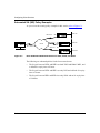
Inbound and Outbound Policies ..................................................................................... C-1
Automated SA (IKE) Policy Examples ..................................................................... C-2
Manual SA Policy Examples ................................................................................... C-5
Manual Protect and Unprotect SA Configuration ......................................................... C-10
Contivity Extranet Switch Interoperability .................................................................... C-17
Supported Versions ............................................................................................... C-17
Configuring Through a Browser ............................................................................ C-17
Terminology ........................................................................................................... C-18
Configuration Specifics ......................................................................................... C-19
Feature Comparison Summary ............................................................................. C-20
Features Supported by Both Platforms ........................................................... C-20
BayRS Features Not Supported by Contivity .................................................. C-20
Contivity Features Not Supported by BayRS .................................................. C-21
BayRS IPsec and NAT .................................................................................... C-21
Troubleshooting Tools ..................................................................................... C-21
BayRS Tools ................................................................................................... C-21
Contivity Tools ................................................................................................. C-22
Symptoms You May See ................................................................................. C-22
Appendix D
Protocol Numbers
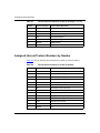
Assigned Internet Protocol Numbers by Name ............................................................. D-2
Assigned Internet Protocol Numbers by Number .......................................................... D-6
Index
viii
308630-14.20 Rev 00
Figures
Figure 1-1.
IPsec Environment: Unique SAs Between Routers .................................1-6
Figure 1-2.
IPsec Concepts: Security Gateways, Security Policies, and SAs ............1-7
Figure 1-3.
IPsec Security Gateways and Security Policies .......................................1-8
Figure 1-4.
Security Associations for Bidirectional Traffic .........................................1-13
Figure C-1.
IPsec Automated Outbound Policies for RTR1, RTR2, and RTR3 .......... C-2
Figure C-2.
IPsec Manual Outbound Policies for RTR1, RTR2, and RTR3 ............... C-6
Figure C-3.
Single Protect/Unprotect SA Pair .......................................................... C-10
Figure C-4.
Multiple Protect/Unprotect SA Pairs ...................................................... C-13
308630-14.20 Rev 00
ix
Tables
Table 1-1.
Security Policy Specifications ................................................................1-14
Table 1-2.
Manual SA Configurations .....................................................................1-15
Table C-1.
Comparison of BayRS and Contivity Terminology ................................ C-18
Table D-1.
Internet Protocol Numbers, Sorted by Acronym ..................................... D-2
Table D-2.
Internet Protocol Numbers, Sorted by Number ....................................... D-6
308630-14.20 Rev 00
xi
Preface
This guide describes the Nortel Networks™ implementation of IP Security and
how to configure it on a Nortel Networks router.
Before You Begin
Before using this guide, you must complete the following procedures. For a new
router:
•
Install the router (see the installation guide that came with your router).
•
Connect the router to the network and create a pilot configuration file (see
Quick-Starting Routers, Configuring Remote Access, or Connecting ASN
Routers to a Network).
Make sure that you are running the latest version of Nortel Networks BayRS™ and
Site Manager software. For information about upgrading BayRS and Site
Manager, see the upgrading guide for your version of BayRS.
308630-14.20 Rev 00
xiii
Configuring IPsec Services
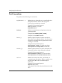
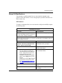
Text Conventions
This guide uses the following text conventions:
angle brackets (< >)
Indicate that you choose the text to enter based on the
description inside the brackets. Do not type the
brackets when entering the command.
Example: If the command syntax is:
ping <ip_address>, you enter:
ping 192.32.10.12
bold text
Indicates command names and options and text that
you need to enter.
Example: Enter show ip {alerts | routes}.
Example: Use the dinfo command.
braces ({})
Indicate required elements in syntax descriptions
where there is more than one option. You must choose
only one of the options. Do not type the braces when
entering the command.
Example: If the command syntax is:
show ip {alerts | routes}, you must enter either:
show ip alerts or show ip routes, but not both.
brackets ([ ])
Indicate optional elements in syntax descriptions. Do
not type the brackets when entering the command.
Example: If the command syntax is:
show ip interfaces [-alerts], you can enter either:
show ip interfaces or show ip interfaces -alerts.
italic text
Indicates new terms, book titles, and variables in
command syntax descriptions. Where a variable is two
or more words, the words are connected by an
underscore.
Example: If the command syntax is:
show at <valid_route>
valid_route is one variable and you substitute one value
for it.
xiv
308630-14.20 Rev 00
Preface
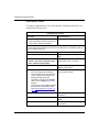
screen text
Indicates system output, for example, prompts and
system messages.
Example: Set Trap Monitor Filters
separator ( > )
Shows menu paths.
Example: Protocols > IP identifies the IP option on the
Protocols menu.
vertical line ( | )
Separates choices for command keywords and
arguments. Enter only one of the choices. Do not type
the vertical line when entering the command.
Example: If the command syntax is:
show ip {alerts | routes}, you enter either:
show ip alerts or show ip routes, but not both.
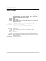
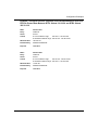
Acronyms
This guide uses the following acronyms:
3DES
Triple DES
AH
Authentication Header
CBC
cipher block chaining
CES
Contivity Extranet Switch
CPU
central processing unit
DES
Data Encryption Standard
ESP
Encapsulating Security Payload
HMAC
Hashing Message Authentication Code
IANA
Internet Assigned Numbers Authority
ICMP
Internet Control Message Protocol
ICV
integrity check value
IETF
Internet Engineering Task Force
IKE
Internet Key Exchange
IP
Internet Protocol
308630-14.20 Rev 00
xv
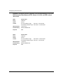
Configuring IPsec Services
IPsec
Internet Protocol Security
ISAKMP/Oakley
Internet Security Association and Key Management
Protocol
IV
initialization vector
MD5
Message Digest 5
MIB
management information base
NAT
Network Address Translation
NBMA
nonbroadcast multiaccess
NPK
node protection key
OSPF
Open Shortest Path First
TCP
Transmission Control Protocol
Hard-Copy Technical Manuals
You can print selected technical manuals and release notes free, directly from the
Internet. Go to the support.baynetworks.com/library/tpubs/ URL. Find the product
for which you need documentation. Then locate the specific category and model
or version for your hardware or software product. Use Adobe Acrobat Reader to
open the manuals and release notes, search for the sections you need, and print
them on most standard printers. Go to Adobe Systems at www.adobe.com to
download a free copy of Acrobat Reader.
You can purchase selected documentation sets, CDs, and technical publications
through the Internet at the www1.fatbrain.com/documentation/nortel/ URL.
xvi
308630-14.20 Rev 00
Preface
How to Get Help
If you purchased a service contract for your Nortel Networks product from a
distributor or authorized reseller, contact the technical support staff for that
distributor or reseller for assistance.
If you purchased a Nortel Networks service program, contact one of the following
Nortel Networks Technical Solutions Centers:
Technical Solutions Center
Telephone
EMEA
(33) (4) 92-966-968
North America
(800) 2LANWAN or (800) 252-6926
Asia Pacific
(61) (2) 9927-8800
China
(800) 810-5000
An Express Routing Code (ERC) is available for many Nortel Networks products
and services. When you use an ERC, your call is routed to a technical support
person who specializes in supporting that product or service. To locate an ERC for
your product or service, go to the www12.nortelnetworks.com/ URL and click
ERC at the bottom of the page.
308630-14.20 Rev 00
xvii
Chapter 1
Overview of IPsec
This chapter describes the emerging Internet Engineering Task Force (IETF)
standards for security services over public networks, commonly referred to as IP
Security or IPsec. The chapter also includes information specific to the Nortel
Networks implementation of IPsec and requirements for that implementation.
This chapter includes the following information:
Topic
Page
About IPsec
1-2
Configuring IPsec and NAT on One Interface
1-2
Network Requirements for Nortel Networks Routers
1-3
IPsec Services
1-4
How IPsec Works
1-5
IPsec Elements
1-7
Security Protocols
1-15
Internet Key Exchange Protocol
1-17
Performance Considerations
1-17
308630-14.20 Rev 00
1-1
Configuring IPsec Services
About IPsec
IP Security is the IETF set of emerging standards for security services for
communications over public networks. The standards are documented in the IETF
Requests for Comments (RFCs) 2401 through 2412. Additional RFCs may be
relevant as well.
These standards were developed to ensure secure, private communications for the
remote access, extranet, and intranet virtual private networks (VPNs) used in
enterprise communications. They are the security architecture for the next
generation of IP, called IPv6, but are available for the current IPv4 Internet as
well.
The Nortel Networks implementation of the IETF standards provides network
(layer 3) security services for wide area network (WAN) communications on
Nortel Networks routers.
Configuring IPsec and NAT on One Interface
You can configure both IPsec and unidirectional network address translation
(NAT) on the same router interface. However, the address ranges you configure in
IPsec policy filters and for NAT cannot overlap.
You can configure IPsec using the BCC. You can configure NAT using either the
BCC or Site Manager. When you configure IPsec and NAT on the same router
interface, IPsec and NAT operate independently and do not pass traffic to each
other.
With both protocols configured on the same router interface, NAT takes
precedence over IPsec. For example, if the destination address of an incoming IP
packet does not match any configured NAT public address, then the packet is
processed by IPsec. If the IP packet contains an address that falls within the
configured range of an IPsec policy, then the packet is either protected, bypassed,
or dropped. A packet with a source address not within any IPsec policy range will
be dropped.
Router interfaces configured for bidirectional NAT do not support IPsec.
1-2
308630-14.20 Rev 00
Overview of IPsec
Network Requirements for Nortel Networks Routers
To install the IP Security software, the router must be running
BayRS Version 13.10 or later and Site Manager Version 7.10 or later. To use
Internet Key Exchange (IKE) and automated security associations (SAs),
BayRS Version 13.20 and Site Manager Version 7.20 or later are required.
Supported Routers
Nortel Networks IP technologies are implemented on BayRS router interfaces
supporting synchronous communications.
IPsec can provide encryption and authentication services to any serial interface on
the following routers:
•
Access Node (AN®)
•
Access Stack Node (ASN™)
•
Advanced Remote Node™ (ARN™)
•
Backbone Node (BN®)
•
System 5000™ router modules
•
Passport® 5430
•
Passport® 2430
Contivity® Extranet Switch (CES) hardware also supports IPsec. CES does not use
BayRS software, but can be configured to interoperate with it. Refer to “Contivity
Extranet Switch Interoperability” on page C-17 and the Contivity documentation
for more information.
Supported WAN Protocols
The Nortel Networks implementation of IPsec supports Point-to-Point Protocol
(PPP) and frame relay WAN protocols. The Nortel Networks IPsec
implementation also supports dial services, which provide backup and demand
services for PPP and frame relay.
308630-14.20 Rev 00
1-3
Configuring IPsec Services
IPsec Services
IPsec services consist of confidentiality, integrity, and authentication services for
data packets traveling between security gateways.
•
Confidentiality ensures the privacy of communications.
•
The integrity service detects modification of data packets.
•
Authentication services verify the origin of every data packet.
Confidentiality
Confidentiality is accomplished by encrypting and decrypting data packets. The
Encapsulating Security Payload (ESP) protocol uses the Data Encryption
Standard (DES) algorithm in cipher block chaining (CBC) mode to encrypt and
decrypt data packets.
You set confidentiality with the cipher algorithm and cipher key parameters. The
cipher algorithm and cipher key are specified in security associations (SAs). A
security association is a relationship in which two peers share the necessary
information to securely protect and unprotect data. The algorithm and key must be
identical on both ends of an IPsec SA.
Integrity
Integrity determines whether the data has been altered during transit. The ESP
protocol ensures that data has not been modified as it passes between the security
gateways. The ESP protocol uses the HMAC MD5 (RFC 2403) or HMAC SHA-1
(RFC 2404) transform.
You set integrity with the integrity algorithm and integrity key parameters. The
integrity algorithm and integrity key must be identical on both ends of an IPsec
SA.
Authentication
Authentication ensures that data has been transmitted by the identified source.
1-4
308630-14.20 Rev 00
Overview of IPsec
Additional IPsec Services
Within the IPsec framework, additional security services are provided. An access
control service ensures authorized use of the network, and an auditing service
tracks all actions and events.
IPsec services can be configured on an interface-by-interface basis. Up to
127 inbound and 127 outbound security policies (customized) are supported on
each IPsec interface.
How IPsec Works
IPsec services are bundled as an IP encryption packet. The packets resemble
ordinary IP packets to Internet routing nodes; only the sending and receiving
devices are involved in the encryption. IPsec packets are delivered over the
Internet like ordinary IP packets to branch offices, corporate partners, or other
remote organizations in a secure, encrypted, and private manner.
Several well-established technologies provide encryption and authentication at the
application layer. IPsec adds security at the underlying network layer, providing a
higher degree of security for all applications, including those without any security
features of their own.
IPsec Protection
To configure a router with IPsec, you first configure the router interface as an
IP interface. Then you add the IPsec software to the IP interface, creating a
security gateway. A security gateway is a router between a trusted network (for
example, the enterprise intranet) and an untrusted network (the Internet) that
provides a security service such as IPsec.
The router interface is secured with inbound and outbound security policies that
filter traffic to and from the router module. The data packets themselves are
protected by IPsec protocol processing specified by SAs.
308630-14.20 Rev 00
1-5
Configuring IPsec Services
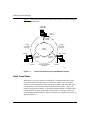
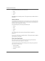
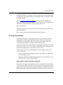
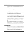
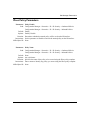
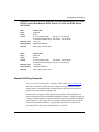
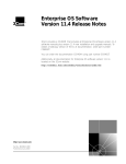
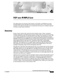
Figure 1-1 shows how IPsec can protect data communications within an enterprise
and from external hosts.
Corporate
headquarters
Server
Router A
IPsec
services
IP security
gateway
Security
associations
(SAs A,B)
Security
associations
(SAs C,A)
Public
network
Branch office
Partner
IP security
gateway
Router B
IP security
gateway
Router C
Host
Host
IPsec
services
Security associations
(SAs B,C)
IPsec
services
IP0088A
Figure 1-1.
IPsec Environment: Unique SAs Between Routers
IPsec Tunnel Mode
When there is a security gateway at each end of a communication, the security
associations between the gateways are said to be in tunnel mode. The tunnel
metaphor refers to data being visible only at the beginning and end points of the
communication. The IP packets protected by IPsec have regular, “visible” IP
headers, but the packet contents are encrypted, and thus hidden. All BayRS IPsec
communications occur in tunnel mode. Tunnel mode is especially effective for
isolating and protecting enterprise traffic traveling across a public data network, as
shown in Figure 1-1.
1-6
308630-14.20 Rev 00
Overview of IPsec
IPsec Elements
IPsec has three important constructs:
•
Security gateways
•
Security policies
•
Security associations
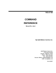
In the IPsec context, hosts communicate across an untrusted network through
security gateways (routers configured for IPsec interfaces). Security policies
determine how the IPsec interfaces handle data packets for the hosts on both ends
of a connection. Security associations apply IPsec services to data packets
traveling between the security gateways.
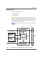
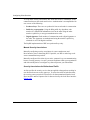
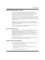
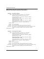
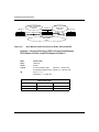
Figure 1-2 shows the logical relationship between security policies and security
associations.
IPsec gateway
WAN interface
Inbound process
Security associations
Unprotect
Unprotect SAs
SAs
Source/Dest Addr, SPI
Cipher Algo/Key,
Integrity Algo/Key
Protect
Protect SAs
SAs
Source/Dest Addr, SPI
Cipher Algo/Key,
Integrity Algo/Key
Inbound
Inboundpolicies
policies
criteria & action
(bypass, drop, log)
Outbound
Outboundpolicies
policies
criteria & action
(bypass, drop, log,
protect)
Security
policy
database
Untrusted
network
Outbound process
IP0087A
Figure 1-2.
IPsec Concepts: Security Gateways, Security Policies, and SAs
308630-14.20 Rev 00
1-7
Configuring IPsec Services
Security Gateways
A security gateway establishes SAs between router interfaces configured with
IPsec software. A Nortel Networks router becomes a security gateway when you
enable IPsec on a WAN interface. In this way, a Nortel Networks router operating
as a security gateway provides IPsec services to its internal hosts and
subnetworks.
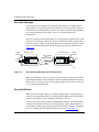
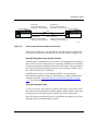
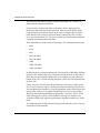
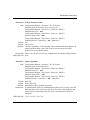
Hosts or networks on the external side of a security gateway (typically, the overall
Internet) are considered “untrusted.” Hosts or subnetworks on the internal side of
a security gateway (nodes on your local intranet) are considered “trusted” because
they are controlled and securely managed by the same network administration
(Figure 1-3).
Trusted
network
Outbound policy
Outbound policy
IPsec interface
Local
host
Security
gateway
Inbound policy (clear text only)
Untrusted
network
IPsec interface
Trusted
network
Remote
host
Security
gateway
Inbound policy (clear text only)
IP0078A
Figure 1-3.
IPsec Security Gateways and Security Policies
When you add IPsec services to a router to create a security gateway, its internal
hosts and subnetworks can communicate with external hosts that directly operate
IPsec services, or with a remote security gateway that provides IPsec services for
its set of hosts and subnetworks.
Security Policies
When you create an IPsec policy, you control which packets a security gateway
protects, how it handles packets to or from particular addresses or in a particular
protocol, and whether it logs information about these actions.
There are two types of IPsec policies: inbound and outbound. An inbound policy
is used for data packets arriving at a security gateway, and an outbound policy is
used for data packets leaving a security gateway. Each IPsec interface can support
up to 127 inbound and 127 outbound security policies (refer to Figure 1-3).
1-8
308630-14.20 Rev 00
Overview of IPsec
The criteria (“selectors”) and action specifications used in your inbound and
outbound policies are stored in the security policy database (SPD).
IPsec defaults in favor of more security rather than less. If an outbound or inbound
packet does not match the criteria of any configured outbound or inbound policy
in the SPD, the packet is dropped.
IPsec discards any outbound clear-text data packet unless you explicitly configure
a policy to bypass or protect it.
Policy Templates
Every IPsec policy is based on a policy template. A policy template is a predefined
policy definition that you can use on any IP interface. The template specifies one
or more criteria and an action to apply to incoming or outgoing data packets.
A policy template and every policy based on it must include at least one criterion
(for example, an IP source address) and one action (for example, an outbound
policy might specify a protect action). A policy template or policy may include
two actions if one of the actions is logging. The criterion specification determines
whether a data packet matches a particular security policy, and the action specifies
how the policy is applied to the packet.
The action specifications that you can include in inbound and outbound policies
are discussed in the following two sections.
Inbound Policies
An inbound policy determines how a security gateway processes data packets
received from an untrusted network. Every packet arriving at a security gateway is
compared with the criteria to determine whether it matches an IPsec policy for
that router. If the incoming packet matches a bypass policy, the router accepts the
packet and, if the policy is so configured, logs it.
If the packet does not match any policy or matches a drop policy, the router rejects
the packet. When a packet does not match any policy, IPsec’s default action is to
drop it.
308630-14.20 Rev 00
1-9
Configuring IPsec Services
For an inbound security policy, the action may be:
•
Drop
•
Bypass
•
Log
Drop and bypass are mutually exclusive. The log action may be added to either, or
used alone.
Outbound Policies
An outbound policy determines how a security gateway processes data packets for
transmission across an untrusted network. You must assign an outbound policy for
all unicast traffic leaving an IPsec interface.
For an outbound policy, the action specification may be:
•
Protect
•
Drop
•
Bypass
•
Log
Any outbound policy with a protect action specification is mapped to a
Protect SA.
Drop, protect, and bypass are mutually exclusive. The log action may be added to
any of the three, or used alone.
Policy Criteria Specification
IPsec software inspects IP packet headers based on the specified criteria to
determine whether a policy applies to a data packet.
You must include at least one of the following criteria, and you may specify all
three criteria in an IPsec policy:
1-10
•
IP source address
•
IP destination address
•
Protocol
308630-14.20 Rev 00
Overview of IPsec
To specify the protocol criterion, you must provide the numeric value assigned to
the protocol for use over the Internet. You can specify only a single protocol value
for each policy. The protocol number is represented in the 1-byte protocol field in
an IP packet header.
Refer to Appendix D, “Protocol Numbers” for a list of protocol numbers. To
obtain the most recent list of the numeric values assigned to various protocols, see
the Internet Assigned Numbers Authority (IANA) Web site at:
http://www.iana.org
The direct path to the list of legal values that you can specify for an IPsec policy
protocol criterion is:
http://www.isi.edu/in-notes/iana/assignments/protocol-numbers
Security Associations
A security association is a relationship in which two peers share the necessary
information to securely protect and unprotect data. An IPsec SA is uniquely
identified by an IP destination address, security parameter index (SPI), and
security protocol identifier (for example, ESP in tunnel mode).
An IPsec policy determines which packets will be handled. An IPsec SA specifies
which IPsec security service (for example, confidentiality) IPsec will apply to the
packets. You can apply one or more IPsec security services.
SAs themselves must be created and shared in a secure manner. There are two
ways to achieve this:
•
Use the automated security negotiation process provided by the Internet Key
Exchange (IKE) protocol.
•
Manually configure the sending and receiving devices with a shared secret. A
shared secret is a unique security identifier.
Automated Security Associations Using IKE
Internet Key Exchange is an automated protocol to establish security associations
over the Internet. (IKE is also referred to as the Internet Security Association Key
Management Protocol with Oakley Key Determination, or ISAKMP/Oakley.) IKE
handles negotiating, establishing, modifying, and deleting security associations.
308630-14.20 Rev 00
1-11
Configuring IPsec Services
To set up these security associations, IKE itself must create a confidential, secure
connection between the sender and receiver. Authentication is accomplished with
one or more of the following:
•
Preshared keys: These are set up ahead of time at each node in a transaction.
•
Public key cryptography: Using the RSA public key algorithm, each
member of a transaction authenticates itself to the other using the other
member’s public key to encrypt an authentication value.
•
Digital signature: Each member of a transaction sends a digital signature to
the other. The signatures are authenticated using the member’s public key,
obtained via an X.509 digital certificate.
The BayRS implementation of IKE uses preshared keys only.
Manual Security Associations
Manually configuring security associations is a more cumbersome and
labor-intensive process than using IKE. If possible, use IKE to make large-scale
secure communications practical.
Manually configured SAs often rely on static, symmetric keys on communicating
hosts or security gateways. As such, you must coordinate within your organization
and with outside parties to configure keys that will protect your information.
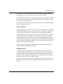
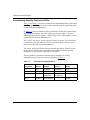
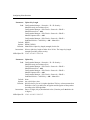
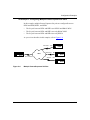
Security Associations for Bidirectional Traffic
An SA specifies the security services that are applied to data packets traveling in
one direction between security gateways. To secure the traffic in both directions,
the security gateway must have a Protect SA for data transmitted from the local
IPsec interface and an Unprotect SA for data received by the local IPsec interface
(Figure 1-4).
1-12
308630-14.20 Rev 00
Overview of IPsec
Security gateway
Protect SA
Source: 132.245.145.195
Destination: 132.245.145.205
Unprotect SA
Source: 132.245.145.195
Destination: 132.245.145.205 Security gateway
Network
132.245.145.205
132.245.145.195
Unprotect SA
Source: 132.245.145.205
Destination: 132.245.145.195
Protect SA
Source: 132.245.145.205
Destination: 132.245.145.195
IP0079A
Figure 1-4.
Security Associations for Bidirectional Traffic
Under most circumstances, you will configure the IKE protocol to negotiate SAs
between security gateways automatically. You can also manually configure SAs.
How IKE Negotiates Security Associations
The IKE protocol automates the process of IPsec SA configuration by creating an
IKE SA for Protect SA and Unprotect SA negotiation. Each IKE peer sends IPsec
SA parameter negotiation information in a secure IKE packet. The peers generate
keys based on the agreed parameters and then verify each other’s identity. Once
this is done, the IPsec SA is established.
The IKE protocol itself is secured through an IKE SA created using the
Diffie-Hellman algorithm (Oakley) to determine the key, and the authentication
methods described in “Automated Security Associations Using IKE” on page
1-11. The Nortel Networks implementation uses a preshared key.
Security Parameter Index
A security parameter index (SPI) is an arbitrary but unique 32-bit (4-byte) value
that, when combined with the IP destination address and the numeric value of the
security protocol used (ESP), uniquely identifies the SA for a data packet.
IPsec discards any incoming ESP packet if the SPI does not match any SA in the
inbound security associations database (SAD).
308630-14.20 Rev 00
1-13
Configuring IPsec Services
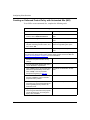
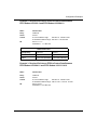
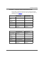
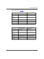
Summarizing Security Policies and SAs
Table 1-1 and Table 1-2 provide a framework for understanding IPsec policies and
SAs. They provide examples of how policies and SAs might be implemented, but
are not meant to be comprehensive.
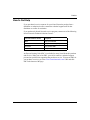
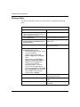
In Table 1-1, each row defines the policy specification for the policy named in the
first column. For example, the “blue” policy specifies two criteria—IP source
address and IP destination address—and the “drop” action. This might be used to
discard all traffic from an undesirable site.
The “yellow” and “green” policies specify a Protect SA action. The yellow policy
covers traffic in just one protocol (TCP) to a particular subnet, while the green
policy covers all traffic to particular addresses.
The “black” policy specifies the Protocol criterion only and the “bypass” action.
In this case the ICMP protocol (typically used for PING functions) is passed
through the security gateway without IPsec encryption.
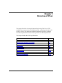
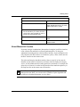
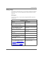
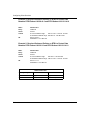
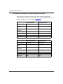
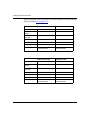
You may define SA parameters (automatically or manually) for a policy
immediately after you specify the policy using them (Table 1-2).
Table 1-1.
1-14
Security Policy Specifications
Policy Name
Protocol
IP Source
Address
IP Destination
Address
Action
Blue
(any)
IP address
IP address
Drop
Yellow
6 (TCP)
IP subnet
IP subnet
Protect SA
Green
(any)
Range of
IP addresses
Range of
IP addresses
Protect SA
Black
1 (ICMP)
Any IP address
Bypass
308630-14.20 Rev 00
Overview of IPsec
In Table 1-2, the IP source and destination addresses for the SA are the tunnel end
points for the IPsec tunnel through which the traffic passes. Intermediate routers
are unaware that the traffic is encrypted, and pass it along just like any other
packet.
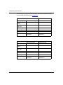
Table 1-2.
Manual SA Configurations
Security Association
Source
Address
Destination
Address
IP address
IP address
IP address
IP address
SPI
Cipher
Integrity
Algorithm
Key
Length
Key
Algorithm
Key
270
DES
40
Hex value
HMAC MD5
Hex value
260
DES
56
Hex value
HMAC MD5
Hex value
Security Protocols
IPsec uses two protocols to provide traffic security:
•
Encapsulating Security Payload (ESP)
•
Authentication Header (AH)
You can use either protocol or both to protect data packets on a VPN. Generally,
only one protocol is necessary.
The Nortel Networks IPsec implementation uses ESP only. Nortel Networks does
not implement the AH protocol because the same functions are available from
ESP.
Encapsulating Security Payload
The ESP protocol provides confidentiality (encryption) services. It can also
provide data integrity, data origin authentication, and an anti-replay service.
•
Data integrity ensures that the data has not been altered.
•
Data origin authentication validates the sending and receiving parties.
•
Anti-replay service ensures that the receiver only receives and processes each
packet once.
308630-14.20 Rev 00
1-15
Configuring IPsec Services
One or more of these security services must be applied whenever ESP is invoked.
ESP applies the following algorithms and transform identifiers to deliver its
services:
•
DES (56-bit)
•
40-bit DES (manual keying only)
•
Triple DES (3DES) (3DES IPsec option only)
•
HMAC Message Digest 5 (MD5)
•
HMAC SHA1
ESP uses the DES algorithm or the Triple DES (3DES) algorithm for encryption.
ESP uses Hashing Message Authentication Code Message Digest 5
(HMAC MD5) or HMAC SHA1 transform identifiers for authentication.
ESP uses the CBC mode of the DES encryption algorithm. CBC is considered the
most secure mode of DES. A 56-bit or 40-bit number, known as a key, controls
encryption and decryption. Key management is automated through IKE, or can be
controlled manually.
Both sides of an SA must use the same encryption service. Normally, you should
use the stronger 56-bit DES key for greater security, or triple DES if appropriate.
However, if you are communicating with a security gateway that is limited to a
40-bit DES key due to cryptography export restrictions, you must use the 40-bit
key.
When ESP protection is used in tunnel mode, an “outer” IP header specifies the
IPsec processing destination, and an “inner” IP header specifies the (actual) target
destination for the packet. The security protocol header appears after the outer IP
header and before the inner one. Only the tunneled packet is protected, not the
outer header.
Authentication Header
The AH protocol provides data integrity, data origin authentication, and optional
anti-replay services. It provides encryption services to the header only, not to the
entire IP packet.
The AH protocol uses HMAC MD5 and HMAC SHA1 transform identifiers. The
AH protocol is not used in the Nortel Networks implementation of IPsec.
1-16
308630-14.20 Rev 00
Overview of IPsec
Internet Key Exchange Protocol
The IKE protocol negotiates and provides private and authenticated keying
material for security associations. Before providing keying material, the IKE
protocol itself must be authenticated, that is, something must create an IKE
security association between the security gateways IKE is servicing.
BayRS software creates an IKE SA through a preshared authentication key. IKE
creates and changes IPsec SAs dynamically, with no user intervention necessary.
This makes them faster and more frequently than they might otherwise be made,
for greater security.
To negotiate a security association, IKE peers form a security association
(an IKE SA) between them. The IKE SA protects the negotiation of the IPsec SA
parameters and key exchange.
The IKE protocol can change IPsec and IKE SA keys based on preconfigured
criteria such as elapsed time or number of bytes sent.
Perfect Forward Secrecy
Perfect forward secrecy (PFS) disassociates each IPsec SA key from others in the
same IKE-negotiated security association. To obtain PFS, IKE uses the
Diffie-Hellman algorithm to exchange keys for each SA. This means that as IKE
and IPsec SAs are automatically rekeyed over the course of IPsec peer
communication, old keys, if compromised, cannot be used to derive previous or
future keys used for other SAs.
With PFS, if an intruder manages to break an encryption key, they gain access to a
limited amount of data (packets protected by a single SA).
Performance Considerations
IPsec performance can vary greatly, and IPsec can impact router performance in
general. Factors that affect performance are:
•
The cryptographic algorithms that IPsec uses
•
Other protocols and features running on the slot that share the same CPU
resources as IPsec
•
The processing power of the BayRS router
308630-14.20 Rev 00
1-17
Configuring IPsec Services
The following information will help you plan and manage CPU resources in
BayRS routers configured with IPsec.
Greater security can adversely affect performance. Before deploying IPsec,
identify the data traffic that must be protected. Effective traffic analysis might
result in minimal performance impact on the router. Configure IPsec to bypass
traffic that does not need to be protected, thereby reducing the CPU resources
used. Also, the amount of CPU resources required varies significantly for different
encryption and authentication algorithms.
These algorithms are listed in order of increasing CPU consumption and security:
•
MD5
•
SHA1
•
DES
•
DES with MD5
•
DES with SHA1
•
3DES
•
3DES with MD5
•
3DES with SHA1
In addition, the key generation and periodic rekeying done by IKE Diffie-Hellman
imposes a CPU burden. Therefore, consider the keying intervals for IKE and for
IPsec that you choose during configuration. Less frequent rekeying reduces the
burden on the CPU. Consider rekeying the phase 1 (IKE) SAs less frequently than
the IPsec SAs.
Finally, the packet size influences the performance of the router. Smaller packet
sizes at a given data rate impose a greater processing load than larger packet sizes.
You can optimize performance by using the information in this section to plan and
manage CPU resources. For example, BayRS IPsec on a BN can fill a 2 Mbps
WAN pipe with bidirectional DES-encrypted traffic. Conversely, 3DES + SHA1
traffic with aggressive phase 1 (IKE) and IPsec rekeying (for example, every
10 minutes) might cause significant performance degradation under heavy traffic
loads.
You might experience SNMP timeouts during periods when the router is carrying
peak loads of protected traffic.
1-18
308630-14.20 Rev 00
Chapter 2
Installing IPsec
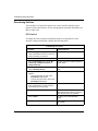
This chapter describes how to install and prepare to use IPsec. Before you
configure IPsec, you need to:
•
Upgrade router software, if necessary.
•
Install IPsec software.
•
Secure your site.
•
Secure your configuration.
•
Use the Technician Interface secure shell to enter a node protection key (NPK)
and seed (kseed), and then enter the same NPK in Site Manager.
This chapter contains the following information:
Topic
Page
Upgrading Router Software
2-2
Installing the IPsec Software
2-2
Securing Your Site
2-4
Securing Your Configuration
2-4
Creating and Using NPKs
2-5
308630-14.20 Rev 00
2-1
Configuring IPsec Services
Upgrading Router Software
To install the IPsec software, you must be running, at a minimum, BayRS Version
13.20 and Site Manager Version 7.20.
If you are upgrading your router software, copy the router image from the upgrade
CD to a directory on your hard drive. To modify an existing image, first use the
Router Files Manager to transfer the image to a directory on your hard drive.
For instructions on upgrading router software, see Upgrading Routers to
Version 14.20. For information about the Image Builder, the Router Files
Manager, and booting routers, see Configuring and Managing Routers with Site
Manager.
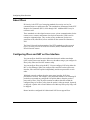
Installing the IPsec Software
Before you can enable and use IPsec services, you must create an IPsec-capable
router image. You create this image during the installation process. The
installation instructions that appear on the IPsec software CD are included in this
section.
To install the IPsec software:
1.
Insert the IPsec software CD into the CD-ROM drive.
2.
Open or create a directory for your router platform (for example, BN).
3.
Copy the files bn.exe and capi.exe to the platform directory.
4.
From Site Manager, start the Image Builder (choose Tools >
Image Builder).
5.
Open the image in the router platform directory (for example, bn.exe).
Note that “Available Components” is empty and that “Current Components”
lists the executables.
6.
Click on Details.
Under 4003x Baseline Router Software, select capi.exe.
7.
Click on Remove.
The file capi.exe is now listed under Available Components.
8.
2-2
Choose File > Save to save the image.
308630-14.20 Rev 00
Installing IPsec
9.
Exit the Image Builder.
Completing the Installation Process
To complete the installation process:
1.
Open the Image Builder directory:
•
On a PC, the default directory is wf\builder.dir\rel<release_number>.
•
On a UNIX platform, the default directory is
~.builder/rel<release_number>.
2.
Remove the file capi.exe from the Image Builder directory. This file is a
1-byte stub file.
3.
Copy the new capi.exe file from the router platform directory (for
example, BN) to the Image Builder directory.
4.
Restart the Image Builder and open the image from which you removed
capi.exe.
5.
Click on Details in the Available Components box.
6.
Select capi.exe and click on Add.
7.
Check the size of the capi.exe file.
If it is less than 1 KB, you have not loaded the IPsec software. Repeat this
procedure or call the Nortel Networks Technical Solutions Center for
assistance.
8.
Save the modified image that includes IPsec to a new file.
9.
Exit the Image Builder.
10. Copy this new image to the router.
11. Reboot the router.
Installing Triple DES Encryption
To use Triple DES (3DES) encryption with IPsec, you must purchase the 3DES
IPsec Option CD, and install the capi.exe file from it. The version of capi.exe on
this CD includes both 56-bit DES encryption and the stronger 3DES encryption.
308630-14.20 Rev 00
2-3
Configuring IPsec Services
Securing Your Site
To enforce IPsec, carefully restrict unauthorized access to the routers that encrypt
data and the workstations that you use to configure IPsec. Keep in mind that the
encryption standards that IPsec uses are public. Your data is secure only if you
properly protect the encryption and authentication keys. The configuration files
that contain these keys include safeguards to prevent unauthorized access.
Securing Your Configuration
Store any files containing encryption keys on diskettes or other removable media,
and keep the media in a secure place. Physically protecting your equipment is
always a good strategy and the easiest way to prevent unauthorized access to these
files.
Always configure your node protection keys (NPKs) locally, not over a network.
When you connect a PC or a workstation to a router console port to configure
encryption, use a machine that is not connected to any other equipment. Make
sure you also protect the routers on which the NPKs reside.
Encryption Keys
IPsec uses a hierarchy of keys to protect and transmit data:
•
NPK—Encrypts the manual cipher and integrity keys for storage on the router
or transfer from Site Manager.
-- Cipher key—Encrypts data that travels across the network in the IKE or
ESP payload. (IKE cipher and integrity keys are not stored on the router.)
-- Integrity key—Calculates the integrity check value (ICV), which is used
at the data packet destination to detect any unauthorized modification of
the ESP or IKE data.
•
Preshared authentication key—Authenticates the IKE SA used to protect the
negotiation and rekeying of IPsec SAs.
Caution: The NPK is the most critical key in the hierarchy. If the NPK is
compromised, all encrypted data on the router can be compromised.
2-4
308630-14.20 Rev 00
Installing IPsec
Random Number Generator
The router software uses the secure random number generator (RNG) to generate
initialization vectors (IVs) that are used in the ESP DES encryption
transformation. These values are statistically random. As its source, the RNG uses
a seed that you supply from the Technician Interface secure shell. See “Entering
an Initial NPK and a Seed for Encryption” on page 2-6.
Creating and Using NPKs
The NPK encrypts manually configured IPsec ESP cipher and integrity keys or
IKE preshared authentication keys for management information base (MIB)
storage. It does not encrypt, decrypt, or authenticate data.
The NPK is stored in the router nonvolatile random access memory (NVRAM). Its
fingerprint, which is a 128-bit version of the NPK generated by a hash algorithm,
is stored in the MIB. For encryption to occur, the NPK and its fingerprint in the
MIB must match.
Create and configure a different NPK for each secure router on your network. The
NPK should be different on every router because, if an NPK is compromised, the
security gateway for the router is compromised. If the same NPK is used for all
secure routers, the entire network could be compromised.
Caution: Make sure you protect all files where NPKs are stored. Store your
NPKs on removable media (for example, diskettes) and keep the media in a
secure location.
308630-14.20 Rev 00
2-5
Configuring IPsec Services
Generating NPKs
You create NPKs using the Technician Interface secure shell. You must then enter
the same NPKs into the Site Manager NPK parameter for that router.
To generate an NPK, use a method available at your site to create random 16-digit
hexadecimal numbers.
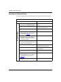
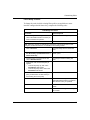
Entering an Initial NPK and a Seed for Encryption
Before you can enable IPsec on a router, you must enter an initial NPK and create
a seed for use by IPsec. You enter the NPK into a router locally, using the console
port and the secure shell section of the Technician Interface. A password protects
access to the secure shell.
IPsec uses the NPK to encrypt and decrypt the cipher and integrity keys, and it
uses the seed specified with the kseed command to generate random numbers
needed by IPsec and IKE.
You cannot access the NPK or the password using the MIB or the routine
Technician Interface debug commands, nor can you invoke the secure shell in a
Telnet session.
Caution: Never use a terminal server to enter the NPK. Instead, use a laptop
computer that you can attach directly to the router. Protect the file containing
NPKs on the laptop.
2-6
308630-14.20 Rev 00
Installing IPsec
To enter an initial NPK and a seed for encryption:
1.
If necessary, create a password for the Technician Interface secure shell
by entering:
kpassword <password>
<password> is an alphanumeric string of up to 16 characters. You are
prompted for your old password. At this point you do not have an old
password, so just press Enter.
2.
At the Technician Interface prompt, enter the secure shell by entering the
following command:
ksession
If you enter the ksession command before setting a password, you will be
prompted to do so. Use the kpassword command described in step 1.
The prompt changes to SSHELL.
3.
Begin generating the encryption seed by entering:
kseed
The secure shell prompts you for a random seed value.
4.
Type a random set of keystrokes. The secure shell informs you when you
have typed the required number of keystrokes.
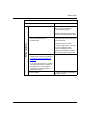
5.
Enter the following command:
kset npk 0x<NPK_value>
<NPK_value> is the 16-digit hexadecimal NPK value that you assigned to the
router that you are configuring. For more information, see “Generating
NPKs” on page 2-6.
The kset npk command stores your NPK value in the router NVRAM and
calculates a hash of this value that it stores in the router MIB.
308630-14.20 Rev 00
2-7
Configuring IPsec Services
6.
Save the configuration by entering:
save config <config_file_name>
<config_file_name> is the name you want to assign to the configuration file.
You cannot exit the secure shell without saving the configuration. This is
necessary so that when you reboot the router with the saved configuration file,
the hash of the NPK in the MIB corresponds with the NPK in NVRAM.
7.
Exit the secure shell by entering:
kexit
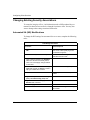
Changing an NPK
To maintain security, periodically change the NPK on each router.
To change an NPK, enter the kset NPK command, using the steps you used to
create the initial NPK (see “Entering an Initial NPK and a Seed for Encryption”
on page 2-6).
The new NPK overwrites the original, and IPsec uses the new NPK value.
However, this does not change the hashed NPK value in the MIB.
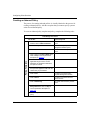
To change the NPK value used by the MIB:
1.
At the Technician Interface prompt, enter the secure shell by entering the
following command:
ksession
2.
Enter your password.
3.
Enter the following command:
ktranslate <old_NPK_value>
<old_NPK_value> is the original NPK value.
The older hashed NPK in the MIB is decrypted, and the new NPK is hashed
and stored in the MIB. The MIB now has the same NPK as the router.
4.
2-8
Save the configuration file.
308630-14.20 Rev 00
Installing IPsec
Monitoring NPKs
If the NPK on a router does not match the NPK in the MIB, IPsec services do not
work. This situation usually occurs when you change a CPU board in a router slot,
and the slot now lacks the current NPK, or you revert to an older configuration
that is protected by an older NPK.
View the router log to make sure that the NPK for each slot matches the NPK
value in the MIB. If the values do not match, use the secure shell to change either
the router NPK value or the MIB NPK value. For more information about
changing NPKs, see “Changing an NPK” on page 2-8.
To view the router log events specific to an NPK in the Technician Interface, enter:
log -ffwidt -eKEYMGR
308630-14.20 Rev 00
2-9
Chapter 3
Starting IPsec
This chapter includes the following information:
Topic
Page
Enabling IPsec and IKE
3-1
Creating Policies
3-2
Creating Security Associations
3-7
Enabling IPsec and IKE
To enable IPsec, configure an IP interface using the Configuration Manager, then
add IPsec services to that interface to create a security gateway.
To enable IPsec and IKE, complete the following tasks:
Site Manager Procedure
You do this
System responds
1. In the Configuration Manager window,
click on the WAN connector on which you
want to configure an IPsec interface.
The Add Circuit window opens.
2. Click on OK.
The WAN Protocols window opens.
3. Choose a WAN protocol (PPP or frame
relay).
The Select Protocols window opens.
(continued)
308630-14.20 Rev 00
3-1
Configuring IPsec Services
Site Manager Procedure (continued)
You do this
System responds
4. Choose IP, IPSEC, and IKE.
The IP Configuration window opens.
Choosing IPSEC automatically selects IP;
choosing IKE automatically selects IPSEC
and IP.
5. Set the following parameters:
• IP Address
• Subnetwork Mask
Click on Help or see Configuring IP, ARP,
RARP, RIP, and OSPF Services.
6. Click on OK.
The IPsec Configuration for Interface
window opens.
When you use Site Manager to configure IPsec on an interface for the first time,
configure the menu items displayed in the IPsec Configuration for Interface
window in sequence, starting with the top item, Outbound Policies. You must set
an outbound policy for an IPsec interface before you can link an SA to it.
Creating Policies
You create inbound and outbound policies for an IPsec interface by using a policy
template. A policy template is a policy definition that you create. You can use a
policy template on any IPsec interface.
Each template contains a complete policy specification (criteria, range, and
action) for the interface. This means that each policy itself is completely specified
by the template. You can modify an individual policy to fit the needs of a specific
interface, independent of the template specifications.
Specifying Criteria
The criteria determine the portion of a packet header (IP source address, IP
destination address, protocol number) that is examined by IPsec. For each
criterion, you must specify a range of values. The range represents the actual
criteria values (that is, the IP addresses that are compared to the address of a
packet).
3-2
308630-14.20 Rev 00
Starting IPsec
Specifying an Action
The action specification in a policy controls how a packet that matches the
specified criteria (and criteria range) is processed. You decide how you want
packets to be processed and apply a policy to implement your decision.
With IPsec, a packet can be processed in one of three ways:
•
The packet can be dropped.
•
The packet can be transmitted or received without alteration.
•
The packet can be protected (outbound only). In this case, an SA is linked to
the policy.
In addition to processing a packet or in the absence of a processing action, packet
receipt or transmission can be recorded in a log. The corresponding policy actions
are:
•
Drop
•
Bypass
•
Protect (outbound only)
•
Log (a message is written to the router log)
The drop, bypass, and protect actions are mutually exclusive. You can specify a
logging action for any of these, or in their absence. If an incoming packet that
does not match any configured policy arrives at an IPsec interface, it is dropped by
default.
Policy Considerations
When you configure a WAN interface with IPsec, all inbound and outbound traffic
on that interface is processed by IPsec, including traffic being forwarded.
For unicast traffic containing routing or control information, consider configuring
policies that allow such traffic to bypass IPsec. For example, to allow ICMP traffic
(such as “ping” or “destination unreachable” messages) to bypass IPsec
processing, configure the first policy for the interface with the protocol criterion
set to 1 (ICMP) and the action specification set to bypass.
If a data packet matches the criteria for more than one policy, the first matching
policy is used.
308630-14.20 Rev 00
3-3
Configuring IPsec Services
Creating an Outbound Policy
To create an outbound policy template and policy, complete the following tasks:
Site Manager Procedure
You do this
System responds
Policy Template
1. In the IPsec Configuration for Interface The IPsec Outbound Policies window
window, click on Outbound Policies. opens.
2. Click on Template.
The IPsec Policy Template
Management window opens.
3. Click on Create.
The Create IPsec Template window
opens.
4. Type a name in the Policy Name field.
Click on Help or see the parameter
description on page A-3.
5. Use the Criteria menu to specify the
applicable range for the IP source
addresses, IP destination addresses,
and protocol criteria.
6. Use the Action menu to add the action
that you want applied to traffic with the
criteria that you just defined.
7. Click on OK.
You return to the IPsec Policy
Template Management window.
8. Click on Done.
You return to the IPsec Outbound
Policies window.
9. Click on Add Policy.
The Create Outbound Policy window
opens.
10. Type the policy name in the
Policy Name field. Click on Help or
see the parameter description on
page A-3.
11. Select a template on which to base this
policy.
(continued)
3-4
308630-14.20 Rev 00
Starting IPsec
Site Manager Procedure (continued)
You do this
System responds
12. Click on OK.
If the policy does not include a Protect
action, you return to the IPsec
Outbound Policies window.
If the policy includes a Protect action,
the Choose SA Type dialog box opens.
Policy Template
13. In the Choose SA Type dialog box,
click on either Manual SA or
Automated SA.
Manual SA lets you choose from a list
of manual Protect SAs or create a new
manual Protect SA.
Automated SA opens the Add
Proposal to Policy window. If a range
of IP source addresses and IP
destination addresses was not
configured in the template, the Add
Policy Ranges dialog box opens first.
14. If you chose Manual SA, see the
instructions for manual configuration in
“Creating Security Associations” on
page 3-7.
If you chose Automated SA, complete
the Add Proposal to Policy window to
associate one or more encryption
methods with a negotiated SA to a
particular IP address.
15. Click on Done.
308630-14.20 Rev 00
You return to the IPsec Configuration
for Interface window.
3-5
Configuring IPsec Services
Creating an Inbound Policy
The process for creating inbound policies is virtually identical to the process for
creating outbound policies, with the exception that you cannot specify a protect
action for an inbound policy.
To create an inbound policy template and policy, complete the following tasks:
Site Manager Procedure
You do this
System responds
1. In the IPsec Configuration for Interface The IPsec Inbound Policies window
window, click on Inbound Policies.
opens.
2. Click on Template.
The IPsec Policy Template
Management window opens.
3. Click on Create.
The Create IPsec Template window
opens.
Policy Template
4. Type a name in the Policy Name field.
Click on Help or see the parameter
description on page A-3.
5. Use the Criteria menu to specify the
applicable range for the IP source
addresses, IP destination addresses,
and protocol criteria.
6. Use the Action menu to add the action
that you want applied to traffic with the
criteria that you just defined.
7. Click on OK.
You return to the IPsec Policy
Template Management window.
8. Click on Done.
You return to the IPsec Inbound
Policies window.
9. Click on Add Policy.
The Create Inbound Policy window
opens.
10. Type the policy name in the
Policy Name field. Click on Help or
see the parameter description on
page A-3.
11. Select a template on which to base this
policy.
(continued)
3-6
308630-14.20 Rev 00
Starting IPsec
Policy Template
Site Manager Procedure (continued)
You do this
System responds
12. Click on OK.
You return to the IPsec Inbound
Policies window.
If the policy includes a protect action,
the Choose SA Type dialog box opens.
13. Click on Done.
You return to the IPsec Configuration
for Interface window.
Creating Security Associations
Security associations enable you to provide bidirectional protection for data
packets traveling between two routers. Each SA establishes security for data
passing in a single direction. A pair of SAs (Protect SA and Unprotect SA) are
created, either automatically by IKE or manually by you, for any IPsec policy
configured on a security gateway. Each SA includes security information such as
algorithm and keys.
You should use automated SA creation (IKE) for greater security and decreased
configuration management overhead.
Automated SA Creation
IKE creates automated SAs, based on the proposals you configure for an IPsec
policy in Site Manager. Each proposal specifies an encryption and/or
authentication transform for the automated SA. You do not have to specify keys
for automated SAs, because IKE creates them dynamically.
You can configure up to four proposals for a policy, in order of preference. IKE
will negotiate an automated SA, based on the first proposal that matches one
configured on the remote security gateway. IKE creates both the inbound and the
outbound SAs based on the results of the proposal negotiation.
308630-14.20 Rev 00
3-7
Configuring IPsec Services
Creating an Outbound Protect Policy with Automated SAs (IKE)
To use IKE to create automated SAs, complete the following tasks:
Site Manager Procedure
You do this
System responds
1. In the IPsec Configuration for Interface
window, click on Outbound Policies.
The IPsec Outbound Policies window
opens.
2. Click on Add Policy.
The Create Outbound Policy window
opens.
3. Type a name for the policy, choose a
template containing a Protect action, and
then click on OK.
If the policy includes a protect action, the
Choose SA Type dialog box opens.
4. Click on Automated SA.
The Add Proposal to Policy window
opens.
Note: If a node protection key has not yet been set, the Node Protection Key dialog box
opens before the Add Proposal to Policy window. Enter an NPK and click on OK. See
“Creating and Using NPKs” on page 2-5 for more information.
5. From the PFS menu, choose Enabled or
Disabled to set perfect forward secrecy
settings.
6. From the Anti-Replay Window Size menu,
choose Disabled or a packet size.
7. Click on Add to specify the SA Destination The Add IKE SA Destination window
opens.
address and preshared key for IKE SAs.
Click on Help or see the parameter
descriptions beginning on page A-4.
8. Enter the IP address and preshared key,
and click on Done to return to the Add
Proposal to Policy window.
9. Click on New Proposal to create an
encryption type proposal that IKE will use
when negotiating SA keys with the SA
destination node.
The Edit IPsec Proposal window opens.
10. Type a proposal name, choose one or
more encryption methods for the proposal,
choose an Expiry type, and change the
Expiry value, if desired.
3-8
308630-14.20 Rev 00
Starting IPsec
Site Manager Procedure (continued)
You do this
System responds
11. Click on Done.
You return to the Edit IPsec Proposal
window. Repeat steps 6 and 7 to create
additional proposals, if needed.
12. In the Edit IPsec Proposal window, choose
the SA destination you created, and then
choose one to four proposals (in order of
priority) from the Proposals menu.
13. Click on OK.
You return to the IPsec Outbound Policies
window.
14. Click on Done.
You return to the IPsec Configuration for
Interface window.
About Manual SA Creation
To protect (encrypt or authenticate) data packets leaving the local IPsec interface,
create a Protect SA and link it to a Protect outbound policy. To decrypt or
authenticate incoming packets at the local IPsec interface, create an Unprotect SA.
(The Unprotect SA does not have to be linked to a policy.) Then, do the same for
the IPsec interface on the remote router.
The cipher and integrity algorithms and keys that you specify in SAs must be
identical on both ends of a connection. You must select the cipher, the integrity
service, or both within the Protect and Unprotect SA parameters. For example, the
cipher key in a Protect SA on the local IP interface must match the cipher key in
the Unprotect SA on the remote router IP interface.
Note: You must configure manual SAs to encrypt, authenticate, or both. Site
Manager does not allow you to create an SA if both the Cipher Algorithm and
the Integrity Algorithm parameters are set to None.
308630-14.20 Rev 00
3-9
Configuring IPsec Services
Creating a Protect SA Manually
To create a Protect SA manually, complete the following tasks:
Site Manager Procedure
You do this
System responds
1. In the IPsec Configuration for Interface
window, click on Manual Protect SA.
The Protect SA List for Interface window
opens.
2. Click on Add.
The IPsec Manual Protect SA window
opens, where the parameters from the
Protect SA List for Interface window
become active.
3. Set the following parameters:
• SA Source IP Address
• SA Destination IP Address
• Security Parameter Index
• Cipher Algorithm
• Cipher Key Length
• Cipher Key
• Integrity Algorithm
• Integrity Key
Position the cursor in a field and click on
Values to display a menu of valid options,
if applicable. Click on Help, or see the
parameter descriptions beginning on
page A-4 for more information.
3-10
4. Click on OK.
You return to the Protect SA List for
Interface window.
5. Repeat steps 2 through 4 to create
additional Protect SAs, if necessary. Click
on Done when you are finished.
You return to the IPsec Configuration for
Interface window.
308630-14.20 Rev 00
Starting IPsec
Creating an Unprotect SA Manually
To create an Unprotect SA manually, complete the following tasks:
Site Manager Procedure
You do this
System responds
1. In the IPsec Configuration for Interface
window, click on Manual Unprotect SA.
The Unprotect SA List for Interface
window opens.
2. Click on Add.
The IPsec Manual Unprotect SA window
opens, where the parameters from the
Unprotect SA List for Interface window
become active.
3. Set the following parameters:
• SA Source IP Address
• SA Destination IP Address
• Security Parameter Index
• Cipher Algorithm
• Cipher Key Length
• Cipher Key
• Integrity Algorithm
• Integrity Key
Position the cursor in a field and click on
Values to display a menu of valid options,
if applicable. Click on Help, or see the
parameter descriptions beginning on
page A-4 for more information.
4. Click on OK.
You return to the Unprotect SA List for
Interface window.
5. Repeat steps 2 through 4 to create
additional Unprotect SAs, if necessary.
Click on Done when you are finished.
You return to the IPsec Configuration for
Interface window.
308630-14.20 Rev 00
3-11
Chapter 4
Customizing IPsec
This chapter contains information about changing an IPsec configuration that you
have already set up. After initial configuration, this may be your most common
task.
This chapter includes the following information:
Topic
Page
Changing Existing Policies
4-1
Changing Existing Security Associations
4-8
Disabling IPsec
4-11
Changing Existing Policies
You may find it necessary to change which policies are applied to data in a
security association, change the order in which multiple policies are applied, or
remove policies.
308630-14.20 Rev 00
4-1
Configuring IPsec Services
Editing a Policy
To edit an existing IPsec policy on a router interface, complete the following
tasks:
Site Manager Procedure
You do this
System responds
1. In the Configuration Manager window,
click on the WAN connector on which you
want to change an IPsec policy.
The Edit Connector dialog box opens.
2. Click on Edit Circuit.
The Circuit Definition window opens.
3. From the Protocols menu, choose Edit
The IPsec [Inbound | Outbound] Policies
IP > IP Security > [Outbound Policies or window opens.
Inbound Policies].
4. Click on Edit Policy.
The Edit IPsec [Inbound | Outbound]
Policies window opens.
5. Change items by selecting them in the
Policy Information text field:
• To remove an action or criterion, select
it and click on Delete.
• To add an action, choose Log,
Protect, or Bypass from the Action
menu.
• To add criteria, choose IP Source
Address, IP Destination Address, or
Protocol from the Criteria menu.
• To change Source Address,
Destination Address, or Protocol
criteria, select the appropriate line.
The range values appear in the Range
Min. and Range Max. boxes below the
text field. Make changes in these
boxes and click on Modify.
4-2
6. Click on OK.
You return to the IPsec [Inbound |
Outbound] Policies window.
7. Click on Done.
You return to the Circuit Definition
window.
8. Click on Done.
You return to the Configuration Manager
main window.
308630-14.20 Rev 00
Customizing IPsec
Adding a Policy
The procedure to add an IPsec policy to a router interface depends on the protocol
used on the interface. Choose the appropriate procedure that follows for PPP or
frame relay.
PPP Protocol
To add an IPsec policy to a router interface configured with PPP, complete the
following tasks:
Site Manager Procedure
You do this
System responds
1. In the Configuration Manager window,
click on the WAN connector on which you
want to change an IPsec policy.
The Edit Connector dialog box opens.
2. Click on Edit Circuit.
The Circuit Definition window opens.
3. From the Protocols menu, choose
Edit IP > IP Security > [Outbound
Policies or Inbound Policies].
The IPsec [Inbound | Outbound] Policies
window opens.
4. Click on Add Policy.
The Create [Inbound | Outbound] Policy
window opens.
5. In the Policy Name field, type a name for
the policy.
6. From the Interfaces list, select the
interface where you want to add the policy.
7. From the Templates list, select a template
on which to base the policy.
8. Click on OK.
If the policy includes a protect action, the
Choose SA Type dialog box opens.
9. If the Choose SA Type dialog opens,
choose Automated SA and follow the
instructions in “Creating an Outbound
Protect Policy with Automated SAs (IKE)”
on page 3-8, or choose Manual SA and
follow the instructions in “Creating a
Protect SA Manually” on page 3-10.
You return to the IPsec [Inbound |
Outbound] Policies window.
(continued)
308630-14.20 Rev 00
4-3
Configuring IPsec Services
Site Manager Procedure (continued)
You do this
System responds
10. Click on Done.
You return to the Circuit Definition
window.
11. Click on Done.
You return to the Configuration Manager
main window.
Frame Relay Protocol
To add an IPsec policy to a router interface configured with frame relay, complete
the following tasks:
Site Manager Procedure
You do this
System responds
1. In the Configuration Manager window,
click on the WAN connector on which you
want to change an IPsec policy.
The Edit Connector dialog box opens.
2. Click on Edit Circuit.
The Frame Relay Circuit Definition
window opens.
3. Click on Services.
The Frame Relay Service List window
opens.
4. Select a service record. From the
Protocols menu, choose Edit IP > IP
Security > [Outbound Policies or
Inbound Policies].
The IPsec [Inbound | Outbound] Policies
window opens.
5. Click on Add Policy.
The Create [Inbound | Outbound] Policy
window opens.
6. In the Policy Name field, type a name for
the policy.
7. From the Interfaces list, select the
interface where you want to add the policy.
8. From the Templates list, select a template
on which to base the policy.
9. Click on OK.
If the policy includes a protect action, the
Choose SA Type dialog box opens.
(continued)
4-4
308630-14.20 Rev 00
Customizing IPsec
Site Manager Procedure (continued)
You do this
System responds
10. If the Choose SA Type dialog opens,
choose Automated SA and follow the
instructions in “Creating an Outbound
Protect Policy with Automated SAs (IKE)”
on page 3-8, or choose Manual SA and
follow the instructions in “Creating a
Protect SA Manually” on page 3-10.
You return to the IPsec [Inbound |
Outbound] Policies window.
11. Click on Done.
You return to the Frame Relay Service
List window.
12. Click on Done.
You return to the Circuit Definition
window.
13. Click on Done.
You return to the Configuration Manager
main window.
308630-14.20 Rev 00
4-5
Configuring IPsec Services
Reordering Policies
The procedure to reorder IPsec policies on a router interface depends on the
protocol used on the interface. Choose the appropriate procedure that follows for
PPP or frame relay.
PPP Protocol
To change the order in which existing IPsec policies are applied on a router
interface configured with PPP, complete the following tasks:
Site Manager Procedure
You do this
System responds
1. In the Configuration Manager window,
click on the WAN connector on which you
want to reorder IPsec policies.
The Edit Connector dialog box opens.
2. Click on Edit Circuit.
The Circuit Definition window opens.
3. From the Protocols menu, choose IP >
IP Security > [Outbound Policies or
Inbound Policies].
The IPsec [Inbound | Outbound] Policies
window opens.
4. Choose the policy you want to move and
click on Reorder Policies.
The Change Precedence dialog box
opens.
5. Change the order in which the policy is
applied:
• To move the policy up, click on the
Insert Before radio button.
• To move the policy down, click on the
Insert After radio button.
6. In the Precedence Number field, type the
policy number before or after which you
are inserting the current policy.
4-6
7. Click on OK.
You return to the IPsec [Inbound |
Outbound] Policies window. The policies
reflect the new order you specified.
8. Click on Done.
You return to the Circuit Definition
window.
9. Click on Done.
You return to the Configuration Manager
main window.
308630-14.20 Rev 00
Customizing IPsec
Frame Relay Protocol
To change the order in which existing IPsec policies are applied on a router
interface configured with frame relay, complete the following tasks:
Site Manager Procedure
You do this
System responds
1. In the Configuration Manager window,
click on the WAN connector on which you
want to reorder IPsec policies.
The Edit Connector dialog box opens.
2. Click on Edit Circuit.
The Circuit Definition window opens.
Note: Although IP Security is available from submenus of the Protocols menu in this
dialog box, the Reorder button is not available in the resulting window.
3. Click on Services.
The Frame Relay Service List window
opens.
4. From the Protocols menu, choose Edit
The IPsec [Inbound | Outbound] Policies
IP > IP Security > [Outbound Policies or window opens.
Inbound Policies].
5. Choose a policy you want to move and
click on Reorder Policies.
The Change Precedence dialog box
opens.
6. Change the order in which the policy is
applied:
• To move the policy up, click on the
Insert Before radio button.
• To move the policy down, click on the
Insert After radio button.
7. In the Precedence Number field, type the
policy number before or after which you
are inserting the current policy.
8. Click on OK.
You return to the IPsec [Inbound |
Outbound] Policies window. The policies
reflect the new order you specified.
9. Click on Done.
You return to the Circuit Definition
window.
10. Click on Done.
You return to the Configuration Manager
main window.
308630-14.20 Rev 00
4-7
Configuring IPsec Services
Changing Existing Security Associations
To ensure the integrity of SAs, vital information such as IKE preshared keys or
manual SA shared secrets need to be changed from time to time. You may also
want to change other settings associated with an SA.
Automated SA (IKE) Modifications
To change the IKE settings for automated SAs on a router, complete the following
tasks:
Site Manager Procedure
You do this
System responds
1. From the Protocols menu, choose IP >
IKE.
The Edit IKE SA Destination window
opens. A list of SAs specifying source
and destination appears.
2. Click on the SA you want to modify.
The SA’s current values appear in the
fields below the list of SAs.
3. Type a name for the SA in the SA Name
field, if the SA does not already have a
name. You cannot apply changes without
an SA name.
4. Place the cursor in the Pre-Shared Key
Type field and click on Values to select a
key type of either HEX or ASCII.
The Values Selection dialog box opens.
5. Select a value and click on OK.
The appropriate Pre-Shared Key field is
enabled.
6. Type a new key in the Pre-Shared Key
(hex) or Pre-Shared Key (ascii) field.
7. Type a new value in the Expiry Value
Minutes field, if desired.
8. Click on Apply.
9. Click on Done.
4-8
You return to the Configuration Manager
main window.
308630-14.20 Rev 00
Customizing IPsec
Manual SA Modifications
The procedure to modify manual SAs on a router interface depends on the
protocol used on the interface. Choose the appropriate procedure that follows for
PPP or frame relay.
PPP Protocol
To change or add manual SAs on a router interface configured with PPP, complete
the following tasks:
Site Manager Procedure
You do this
System responds
1. In the Configuration Manager window,
click on the WAN connector on which you
want to add or change manual SAs.
The Edit Connector dialog box opens.
Note: Although the menu path IP > IP Security > Manual SAs is available from the
Protocols menu without clicking on a connector, the Add button is not available unless you
choose a specific connector.
2. Click on Edit Circuit.
The Circuit Definition window opens.
3. From the Protocols menu, choose
Edit IP > IP Security > [Manual Protect
SAs or Manual Unprotect SAs].
You may be prompted for the Node
Protection Key. If not, go to step 5.
4. Type the NPK and click on OK.
The [Protect | Unprotect] SA List for
Interface window opens.
You return to the [Protect | Unprotect] SA
5. Change or add an SA:
List for Interface window.
• If you are changing an existing SA,
choose the SA you want to alter from
the list. Change the five Cipher and
Integrity fields by typing new
information or clicking on the Values
button. Click on Apply when you are
finished.
• To add an SA, click on Add. Complete
the Manual SA Configuration screen.
(See “About Manual SA Creation” on
page 3-9.) Click on Done.
6. Click on Done.
You return to the Circuit Definition
window.
7. Click on Done.
You return to the Configuration Manager
main window.
308630-14.20 Rev 00
4-9
Configuring IPsec Services
Frame Relay Protocol
To change or add manual SAs on a router interface configured with frame relay,
complete the following tasks:
Site Manager Procedure
You do this
System responds
1. In the Configuration Manager window,
click on the WAN connector on which you
want to add or change manual SAs.
The Edit Connector dialog box opens.
Note: Although the menu path IP > IP Security > Manual SAs is available from the
Protocols menu without clicking on a connector, the Add button is not available unless you
choose a specific connector.
2. Click on Edit Circuit.
The Circuit Definition window opens.
3. Click on Services.
The Frame Relay Service List window
opens.
4. From the Protocols menu, choose
Edit IP > IP Security > [Manual Protect
SAs or Manual Unprotect SAs].
You may be prompted for the Node
Protection Key. If not, go to step 6.
5. Type the NPK and click on OK.
The [Protect | Unprotect] SA List for
Interface window opens.
You return to the [Protect | Unprotect] SA
6. Change or add an SA:
List for Interface window.
• If you are changing an existing SA,
choose the SA you want to alter from
the list. Change the five Cipher and
Integrity fields by typing new
information or clicking on the Values
button. Click on Apply when you are
finished.
• To add an SA, click on Add. Complete
the Manual SA Configuration screen.
(See “About Manual SA Creation” on
page 3-9.)
4-10
7. Click on Done.
You return to the Frame Relay Services
List window.
8. Click on Done.
You return to the Circuit Definition
window.
9. Click on Done.
You return to the Configuration Manager
main window.
308630-14.20 Rev 00
Customizing IPsec
Disabling IPsec
To disable IPsec on all router interfaces configured for it, complete the following
tasks:
Site Manager Path
You do this
System responds
1. In the Configuration Manager window,
choose Protocols.
The Protocols menu opens.
2. Choose IP.
The IP menu opens.
3. Choose IP Security.
The IP Security menu opens.
4. Choose Globals.
The Edit IP Security Global Parameters
window opens.
5. Set the IP Security Enable parameter to
Disable. Click on Help or see the
parameter description on page A-2 for
more information.
6. Click on Done.
You return to the Configuration Manager
window.
Note: Disabling IPsec on a router or individual interface also disables IKE on
that router or interface automatically.
To disable IPsec on an individual interface, complete the following tasks:
Site Manager Path
You do this
System responds
1. In the Configuration Manager window,
click on an existing IPsec interface.
The Edit Connector window opens.
2. Click on Edit Circuit.
The Circuit Definition window opens.
3. From the Protocols menu, choose
Edit IP > IP Security >Enable Ipsec.
The Enable IP Security dialog box opens.
4. Click in the IP Security Enable field.
5. Click on Values and then select Disable.
308630-14.20 Rev 00
4-11
Configuring IPsec Services
Site Manager Path (continued)
4-12
You do this
System responds
6. Click on Done.
You return to the Circuit Definition
window.
7. Choose File > Exit.
You return to the Configuration Manager
window.
308630-14.20 Rev 00
Appendix A
Site Manager Parameters
This appendix describes the Site Manager parameters for:
•
Creating a node protection key (NPK)
•
Enabling IPsec
•
Configuring IPsec policies
•
Manually configuring IPsec security associations
•
Using IKE to create security associations
Node Protection Key Parameter
Parameter: Node Protection Key
Path: Configuration Manager > Protocols > IP > IP Security >
Manual Security Associations (SAs)
Configuration Manager > Protocols > IP > IKE
Default: None
Options: An 8-byte value
Function: Used as a cryptographic key for protecting sensitive MIB objects. The NPK
value is stored in NVRAM. The IPsec software performs a hash of the NPK
value, which it places in a special MIB attribute. The NPK value stored in
NVRAM is unique to the router. It is used to encrypt the cipher and integrity
keys before they are stored in the router MIB.
Instructions: Enter a 16-digit hexadecimal value. (Enter the prefix 0x before the digits.)
MIB Object ID: None
308630-14.20 Rev 00
A-1
Configuring IPsec Services
IPsec Parameters
Parameter: IP Security Enable
Path: Configuration Manager > Protocols > IP > IP Security > Globals (global setting)
Configuration Manager > Edit Circuit > Protocols > Edit IP > IP Security >
Enable IPsec (individual IPsec interface setting)
Default: Enable
Options: Enable | Disable
Function: Enables or disables IPsec on a router. If this parameter is set to Disable, you
cannot implement IPsec.
Instructions: To implement IP security on a router, set this parameter to Enable.
MIB Object ID: 1.3.6.1.4.1.18.3.5.3.26.1.2 (global)
1.3.6.1.4.1.18.3.5.3.2.1.24.1.59 (individual IPsec interface)
Parameter: Maximum SPI
Configuration Manager > Protocols > IP > IP Security > Globals
384
256 to 65535
Specifies the maximum acceptable SPI value for manually configured SAs.
Enter an integer that represents the maximum SPI value required for manual
SAs for this interface.
MIB Object ID: 1.3.6.1.4.1.18.3.5.3.26.1.5
Path:
Default:
Options:
Function:
Instructions:
A-2
308630-14.20 Rev 00
Site Manager Parameters
IPsec Policy Parameters
Parameter: Policy Enable
Path: Configuration Manager > Protocols > IP > IP Security > Outbound Policies
Configuration Manager > Protocols > IP > IP Security > Inbound Policies
Default: Enable
Options: Enable | Disable
Function: Determines whether the named policy will be used on the IP interface.
Instructions: Set this parameter to Enable to activate the named policy on the IP interface.
MIB Object ID: None
Parameter: Policy Name
Path: Configuration Manager > Protocols > IP > IP Security > Outbound Policies
Configuration Manager > Protocols > IP > IP Security > Inbound Policies
Default: None
Options: Any valid name
Function: Specifies the name of the policy to be created using the IPsec policy template.
Instructions: Enter a name to identify any policy you create using the IPsec policy template.
MIB Object ID: None
308630-14.20 Rev 00
A-3
Configuring IPsec Services
Manual Security Association Parameters
Parameter: SA Source IP Address
Path: Configuration Manager > Protocols > IP > IP Security >
Manual Security Associations (SAs) (viewing only)
Configuration Manager > Edit Circuit > Protocols > Edit IP >
Manual Protect SAs > Add
Configuration Manager > Edit Circuit > Protocols > Edit IP >
Manual Unprotect SAs > Add
Configuration Manager > Edit Circuit > Protocols > Edit IP >
Outbound Policies > Add Policy > OK > Manual SA
Default: None
Options: Any valid IP address
Function: Specifies the IP address of the source interface for this SA.
Instructions: For a Protect SA, enter the IP address of the local IPsec interface. For an
Unprotect SA, enter the IP address of the remote IPsec interface.
MIB Object ID: None
Parameter: SA Destination IP Address
Path: Configuration Manager > Protocols > IP > IP Security >
Manual Security Associations (SAs) (viewing only)
Configuration Manager > Edit Circuit > Protocols > Edit IP >
Manual Protect SAs > Add
Configuration Manager > Edit Circuit > Protocols > Edit IP >
Manual Unprotect SAs > Add
Configuration Manager > Edit Circuit > Protocols > Edit IP >
Outbound Policies > Add Policy > OK > Manual SA
Default: None
Options: Any valid IP address
Function: Specifies the IP address of the destination interface for this SA.
Instructions: For a Protect SA, enter the IP address of the remote IPsec interface. For an
Unprotect SA, enter the IP address of the local IPsec interface.
MIB Object ID: None
A-4
308630-14.20 Rev 00
Site Manager Parameters
Parameter: Security Parameter Index
Path: Configuration Manager > Protocols > IP > IP Security >
Manual Security Associations (SAs) (viewing only)
Configuration Manager > Edit Circuit > Protocols > Edit IP >
Manual Protect SAs > Add
Configuration Manager > Edit Circuit > Protocols > Edit IP >
Manual Unprotect SAs > Add
Configuration Manager > Edit Circuit > Protocols > Edit IP >
Outbound Policies > Add Policy > OK > Manual SA
Default: 256
Options: 256 to 65535
Function: The SPI is an arbitrary 32-bit value that, when combined with the destination IP
address and the numeric value of the security protocol being used (ESP),
identifies the SA for the data packet.
Instructions: Enter a value from 256 to the value configured for the Maximum SPI parameter.
MIB Object ID: None
Parameter: Cipher Algorithm
Path: Configuration Manager > Protocols > IP > IP Security >
Manual Security Associations (SAs)
Configuration Manager > Edit Circuit > Protocols > Edit IP >
Manual Protect SAs > Add
Configuration Manager > Edit Circuit > Protocols > Edit IP >
Manual Unprotect SAs > Add
Configuration Manager > Edit Circuit > Protocols > Edit IP >
Outbound Policies > Add Policy > OK > Manual SA
Default: DES CBC
Options: None | DES CBC
Function: Identifies the cipher algorithm for this SA.
Instructions: To implement the cipher (or confidential/encrypted) level of security, select the
DES algorithm. If you select None, this level of security is not applied to data
packets processed according to this SA; that is, the data packets will not be
encrypted.
MIB Object ID: 1.3.6.1.4.1.18.3.5.3.26.5.1.6
308630-14.20 Rev 00
A-5
Configuring IPsec Services
Parameter: Cipher Key Length
Path: Configuration Manager > Protocols > IP > IP Security >
Manual Security Associations (SAs)
Configuration Manager > Edit Circuit > Protocols > Edit IP >
Manual Protect SAs > Add
Configuration Manager > Edit Circuit > Protocols > Edit IP >
Manual Unprotect SAs > Add
Configuration Manager > Edit Circuit > Protocols > Edit IP >
Outbound Policies > Add Policy > OK > Manual SA
Default: DES56
Options: DES40 | DES56
Function: Identifies the cipher key length (strength) for this SA.
Instructions: Select a cipher key length of either 40 or 56 bits. The longer key length
(strength) provides greater security.
MIB Object ID: 1.3.6.1.4.1.18.3.5.3.26.5.1.8
Parameter: Cipher Key
Path: Configuration Manager > Protocols > IP > IP Security >
Manual Security Associations (SAs)
Configuration Manager > Edit Circuit > Protocols > Edit IP >
Manual Protect SAs > Add
Configuration Manager > Edit Circuit > Protocols > Edit IP >
Manual Unprotect SAs > Add
Configuration Manager > Edit Circuit > Protocols > Edit IP >
Outbound Policies > Add Policy > OK > Manual SA
Default: None
Options: Any valid 8-byte value
Function: Specifies the key for an SA cipher algorithm. This key value must match on
both sides of an SA to enable the encryption and decryption of data packets
according to the DES algorithm.
Instructions: Enter a 16-digit (8-byte) hexadecimal value. (Enter the prefix 0x before the
16 digits.)
MIB Object ID: 1.3.6.1.4.1.18.3.5.3.26.5.1.7
A-6
308630-14.20 Rev 00
Site Manager Parameters
Parameter: Integrity Algorithm
Path: Configuration Manager > Protocols > IP > IP Security >
Manual Security Associations (SAs)
Configuration Manager > Edit Circuit > Protocols > Edit IP >
Manual Protect SAs > Add
Configuration Manager > Edit Circuit > Protocols > Edit IP >
Manual Unprotect SAs > Add
Configuration Manager > Edit Circuit > Protocols > Edit IP >
Outbound Policies > Add Policy > OK > Manual SA
Default: None
Options: None | HMAC MD5
Function: Enables implementation of the HMAC MD5 algorithm, which determines
whether a data packet was changed between the source and destination.
Instructions: To implement the security integrity level, select the HMAC MD5 algorithm. If
you select None, this level of security is not applied to data packets processed
according to this SA; that is, IP security cannot determine whether a data packet
was changed between the source and destination.
MIB Object ID: 1.3.6.1.4.1.18.3.5.3.26.5.1.9
308630-14.20 Rev 00
A-7
Configuring IPsec Services
Parameter: Integrity Key
Path: Configuration Manager > Protocols > IP > IP Security >
Manual Security Associations (SAs)
Configuration Manager > Edit Circuit > Protocols > Edit IP >
Manual Protect SAs > Add
Configuration Manager > Edit Circuit > Protocols > Edit IP >
Manual Unprotect SAs > Add
Configuration Manager > Edit Circuit > Protocols > Edit IP >
Outbound Policies > Add Policy > OK > Manual SA
Default: None
Options: Any valid 16-byte value
Function: Specifies the key for an SA integrity algorithm. This key value must match on
both sides of an SA to enable the integrity algorithm to determine whether a
data packet was changed between the source and destination.
Instructions: To establish the integrity level of IP security, enter a 32-digit hexadecimal value.
(Enter the prefix 0x before the 32 digits.)
MIB Object ID: 1.3.6.1.4.1.18.3.5.3.26.5.1.10
A-8
308630-14.20 Rev 00
Site Manager Parameters
Automated Security Association (IKE) Parameters
Parameter: SA Name
Path: Configuration Manager > Protocols > IP > IKE
Configuration Manager > Edit Circuit > Protocols > Edit IP > IKE
Default: None
Options: Any text string
Function: Used to identify various IKE SAs as you alter them.
Instructions: Enter a meaningful alphanumeric string to identify the SA.
MIB Object ID: 1.3.6.1.4.1.18.3.5.27.1.1.8
Parameter: Pre-Shared Key Type
Path: Configuration Manager > Protocols > IP > IKE
Configuration Manager > Edit Circuit > Protocols > Edit IP > IKE
Default: ASCII
Options: ASCII | HEX
Function: Determines which type of preshared key is used, activating the appropriate field
for you to enter a preshared key.
Instructions: Choose the pre-shared key type. Configure the same preshared key type as the
destination router.
MIB Object ID: None
Parameter: Pre-Shared Key (ascii)
Path: Configuration Manager > Protocols > IP > IKE
Configuration Manager > Edit Circuit > Protocols > Edit IP > IKE
Default: None
Options: Any ASCII value
Function: Used as a cryptographic key for creating IKE SAs between routers. IKE is then
used to create automated SAs for data packets.
Instructions: Enter an ASCII string. Configure the same preshared key on the destination
router.
MIB Object ID: None
308630-14.20 Rev 00
A-9
Configuring IPsec Services
Parameter: Pre-Shared Key (hex)
Path: Configuration Manager > Protocols > IP > IKE
Configuration Manager > Edit Circuit > Protocols > Edit IP > IKE
Default: None
Options: Any hexadecimal value
Function: Used as a cryptographic key for creating IKE SAs between routers. IKE is then
used to create automated SAs for data packets.
Instructions: Enter a hexadecimal number. (Enter the prefix 0x before the digits.) Configure
the same preshared key on the destination router.
MIB Object ID: 1.3.6.1.4.1.18.3.5.27.1.1.9
Parameter: Expiry Value Minutes
Path: Configuration Manager > Protocols > IP > IKE
Configuration Manager > Edit Circuit > Protocols > Edit IP > IKE
Default: 480
Options: Any integer
Function: Specifies when an SA key will expire.
Instructions: Enter a value that is appropriate for your site.
MIB Object ID: 1.3.6.1.4.1.18.3.5.27.1.1.10
Parameter: SA Destination
Path: Configuration Manager > Add Circuit > WAN Protocols > PPP | Frame Relay >
Select Protocols > IKE > IPsec Configuration for Interface > Outbound Policies
Configuration Manager > Edit Circuit > Protocols > Edit IP > IKE > Add
Default: None
Options: Any valid IP address.
Function: Specifies the IP address of the destination interface for this automated SA.
Instructions: Enter the IP address of the remote IPsec interface that will negotiate automated
SAs using the specified preshared key.
MIB Object ID: 1.3.6.1.4.1.18.3.5.27.1.1.3
A-10
308630-14.20 Rev 00
Site Manager Parameters
Parameter: Anti-Replay Window Size
Path: Configuration Manager > Add Circuit > WAN Protocols > PPP | Frame Relay >
Select Protocols > IKE > IPsec Configuration for Interface >
Outbound Policies | Inbound Policies > Add Policy
Configuration Manager > Edit Circuit > Protocols > Edit IP > IP Security >
Outbound Policies | Inbound Policies > Edit Proposal
Default: 64 Packets
Options: Disabled | 32 Packets | 64 Packets | 128 Packets
Function: Specifies the number of packets that are used for replay checking. Anti-replay
checking examines the sequence number of encrypted packets received and
determines whether the packet has been received before.
Instructions: Choose a number of packets to track for anti-replay checking, or choose
Disabled to turn this feature off.
MIB Object ID: None
Parameter: PFS (Perfect Forward Secrecy)
Path: Configuration Manager > Add Circuit > WAN Protocols > PPP | Frame Relay >
Select Protocols > IKE > IPsec Configuration for Interface >
Outbound Policies | Inbound Policies > Add Policy
Configuration Manager > Edit Circuit > Protocols > Edit IP > IP Security >
Outbound Policies | Inbound Policies > Edit Proposal
Default: Enabled
Options: Enabled | Disabled
Function: Specifies whether perfect forward secrecy is used for this SA.
Instructions: Choose Enabled or Disabled from the list.
MIB Object ID: None
308630-14.20 Rev 00
A-11
Appendix B
Definitions of k Commands
This appendix contains definitions of the “k” commands that you use to work in
the Technician Interface secure shell.
Command
System Response
kexit
Exits the secure shell.
kpassword
Changes the password of the secure shell.
kseed
Initializes the cryptographic random number generator while in
the secure shell.
ksession
Initiates a secure shell session.
kset <subcommand>
[<flags>]
Sets parameter values in the secure shell.
Example: kset npk <value> sets the router node protection
key.
Also sets protected IPsec MIB objects (keys). The kset
command encrypts the value specified using the
NPK, and writes the encrypted value to the MIB.
Example: kset ipsec
wfIpsecEspSaEntry.wfIpsecEspSaManualCipherKey.100.
1.1.1.100.1.1.2.256 0x1234567890abcdef
ktranslate <old_NPK> Translates a configuration from an old node protection key
(NPK) value to the current NPK value.
Example: ktranslate <old_NPK>
308630-14.20 Rev 00
B-1
Appendix C
Configuration Examples
This appendix provides configuration examples for both automated and manual
security associations. Configuration of outbound and inbound policies is similar
for both automated and manual SAs. Details for configuring the Protect and
Unprotect SAs are necessary only if you are using the manual process.
Inbound and Outbound Policies
All unicast traffic must be defined by a security policy. Traffic traveling from a
security gateway is defined by an outbound policy; traffic traveling to a secure
gateway is defined by an inbound policy. Inbound protected traffic that is
associated with an Unprotect SA configured on the interface does not require a
policy.
308630-14.20 Rev 00
C-1
Configuring IPsec Services
Automated SA (IKE) Policy Examples
As you review the security policy examples in this section, refer to Figure C-1.
189.132.10.1 - S52
192.32.10.0
RTR2
S51
129.43.12.19 - S28
Internet
INET
RTR1
S32
S31 - 119.68.12.1
192.32.20.0
RTR3
S27
192.32.1.5 - S33
192.32.5.0
RTR4
Figure C-1.
192.32.30.0
S31
IPsec Automated Outbound Policies for RTR1, RTR2, and RTR3
The following are outbound policies for the four routers shown:
C-2
•
The SA pair between RTR1 and RTR2 use both 3DES and HMAC MD5, and
a default SA expiry time of 8 hours.
•
The SA pair between RTR1 and RTR3 use only DES and a default SA expiry
time of 8 hours.
•
The SA pair between RTR1 and RTR4 use only SHA1 and an SA expiry time
of 24 hours.
308630-14.20 Rev 00
Configuration Examples
Example 1: Required Policies, Proposals, and SA Destinations on RTR1 and
RTR2 to Protect Data Between RTR1 Subnet 192.32.5.0 and RTR2 Subnet
192.32.10.0
RTR 1
Interface S31
Policy
Action
Criteria
SA Destination
Preshared Key
Outbound
Protect
IP source address range:
192.32.5.0 - 192.32.5.255
IP destination address range: 192.32.10.0 - 192.32.10.255
189.132.10.1
0xabba1234daba1234
Proposal
3DES-MD5
RTR 2
Interface S52
Policy
Action
Criteria
SA Destination
Preshared Key
Outbound
Protect
IP source address range:
192.32.10.0 - 192.32.10.255
IP destination address range: 192.32.5.0 - 192.32.5.255
119.68.12.1
0xabba1234daba1234
Proposal
3DES-MD5
308630-14.20 Rev 00
C-3
Configuring IPsec Services
Example 2: Required Policies, Proposals, and SA Destinations on RTR1 and
RTR3 to Protect Data Between RTR1 Subnet 192.32.5.0 and RTR3 subnet
192.32.20.0
C-4
RTR 1
Interface S31
Policy
Action
Criteria
SA Destination
Preshared Key
Outbound
Protect
IP source address range:
192.32.5.0 - 192.32.5.255
IP destination address range: 192.32.20.0 - 192.32.20.255
129.43.12.19
0xbeef1234daba1234
Proposal
DES
RTR 3
Interface S28
Policy
Action
Criteria
SA Destination
Preshared Key
Outbound
Protect
IP source address range:
192.32.20.0 - 192.32.20.255
IP destination address range: 192.32.5.0 - 192.32.5.255
119.68.12.1
0xbeef1234daba1234
Proposal
DES
308630-14.20 Rev 00
Configuration Examples
Example 3: Required Policies, Proposals, and SA Destinations on RTR1 and
RTR4 to Protect Data Between RTR1 Subnet 192.32.5.0 and RTR4 Subnet
192.32.30.0
RTR 1
Interface S31
Policy
Action
Criteria
SA Destination
Preshared Key
Outbound
Protect
IP source address range:
192.32.5.0 - 192.32.5.255
IP destination address range: 192.32.30.0 - 192.32.30.255
192.32.1.5
0xabba1579daba1234
Proposal
SHA1, expiry minutes 1440
RTR 4
Interface S33
Policy
Action
Criteria
SA Destination
Preshared Key
Outbound
Protect
IP source address range:
192.32.30.0 - 192.32.30.255
IP destination address range: 192.32.5.0 - 192.32.5.255
119.68.12.1
0xabba1579daba1234
Proposal
SHA1, expiry minutes 1440
Manual SA Policy Examples
As you review the security policy examples in this section, refer to Figure C-2.
All of the routers have OSPF interfaces configured for type NBMA transmit
unicast frames. An outbound and an inbound bypass policy protect all unicast
traffic for the specified router subnetworks.
Security policy examples 1 and 2 show how to configure outbound policies to
protect all unicast traffic between RTR1 and RTR2; examples 3 and 4 show how to
configure outbound policies to protect all unicast traffic between RTR2 and RTR3;
and examples 5, 6, and 7 show how to configure outbound policies to protect all
traffic between RTR1 and RTR3. A bypass inbound policy is in effect for all
incoming traffic to the routers so that no SAs are required.
308630-14.20 Rev 00
C-5
Configuring IPsec Services
Protect / Unprotect SA
RTR1 to RTR2
SPI 256
192.32.5.0
Protect / Unprotect SA
RTR2 to RTR3
SPI 256
192.28.41.0
12
192.131.141.0
IP / IPsec / RIP
IP / IPsec / OSPF(Type: NBMA)
12
12
RTR1
Figure C-2.
S21
1.1.1.1
S21
1.1.1.2
RTR2
S31
2.2.2.1
S11
2.2.2.2
RTR3
Protect / Unprotect SA
RTR1 to RTR3
SPI 257
IPsec Manual Outbound Policies for RTR1, RTR2, and RTR3
Example 1: Required Policies on RTR1 to Protect Data Between
RTR1 Subnet 192.32.5.0 and RTR2 Subnet 192.28.41.0
RTR 1
Interface S21
Policy
Action
Criteria
Outbound
Protect
IP source address range:
192.32.5.0 - 192.32.5.255
IP destination address range: 192.28.41.0 - 192.28.41.255
Source: 1.1.1.1
Destination: 1.1.1.2 SPI 256
SA
RTR1 Interface S21
C-6
Security Policy
Outbound
Inbound
Action
Bypass
Bypass
Criteria
Protocol 89 (OSPFIGP) Protocol 89 (OSPFIGP)
308630-14.20 Rev 00
Configuration Examples
Example 2: Required Policies on RTR2 to Protect Data Between
RTR1 Subnet 192.32.5.0 and RTR2 Subnet 192.28.41.0
RTR 2
Interface S21
Policy
Action
Criteria
Outbound
Protect
IP source address range:
192.28.41.0 - 192.28.41.255
IP destination address range: 192.32.5.0 - 192.32.5.255
Source: 1.1.1.2
Destination: 1.1.1.1 SPI 256
SA
RTR2 Interface S21
Security Policy
Outbound
Inbound
Action
Bypass
Bypass
Criteria
Protocol 89 (OSPFIGP) Protocol 89 (OSPFIGP)
Example 3: Required Policies on RTR2 to Protect Data Between
RTR2 Subnet 192.28.41.0 and RTR3 Subnet 192.131.141.0
RTR 2
Interface S31
Policy
Action
Criteria
Outbound
Protect
IP source address range:
192.28.41.0 - 192.28.41.255
IP destination address range: 192.131.141.0 - 192.131.141.255
Source: 2.2.2.1
Destination: 2.2.2.2 SPI 256
SA
308630-14.20 Rev 00
C-7
Configuring IPsec Services
Example 4: Required Outbound Policies on RTR3 to Protect Data
Between RTR2 Subnet 192.28.41.0 and RTR3 Subnet 192.131.141.0
RTR 3
Interface S11
Policy
Action
Criteria
Outbound
Protect
IP source address range:
192.131.141.0 - 192.131.141.255
IP destination address range: 192.28.41.0 - 192.28.41.255
Source: 2.2.2.2
Destination: 2.2.2.1 SPI 256
SA
Example 5: Required Outbound Policies on RTR1 to Protect Data
Between RTR1 Subnet 192.32.5.0 and RTR3 Subnet 192.131.141.0
RTR 1
Interface S21
Policy
Action
Criteria
Outbound
Protect
IP source address range:
192.32.5.0 - 192.32.5.255
IP destination address range: 192.131.141.0 - 192.131.141.255
Source: 1.1.1.1
Destination: 2.2.2.2 SPI 257
SA
RTR2 Interface S21
C-8
Security Policy
Outbound
Inbound
Action
Bypass
Bypass
Criteria
Protocol 89 (OSPFIGP) Protocol 89 (OSPFIGP)
308630-14.20 Rev 00
Configuration Examples
Example 6: Required Policies on RTR2 to Allow ESP Traffic to Pass Through
and OSPF to Exchange Routing Updates Between
RTR1 and RTR2
RTR2 Interface S21
Security Policy
Outbound
Inbound
Action
Bypass
Bypass
Criteria
Protocol 89 (OSPFIGP) Protocol 89 (OSPFIGP)
Security Policy
Outbound
Inbound
Action
Bypass
Bypass
Criteria
Protocol 50 (ESP)
Protocol 50 (ESP)
RTR2 Interface S31
Security Policy
Outbound
Inbound
Action
Bypass
Bypass
Criteria
Protocol 50 (ESP)
Protocol 50 (ESP)
Example 7: Required Policies on RTR3 to Protect Data Between
RTR3 Subnet 192.131.141.0 and RTR1 192.32.5.0
RTR 3
Interface S11
Policy
Action
Criteria
Outbound
Protect
IP source address range:
192.131.141.0 - 192.131.141.255
IP destination address range: 192.32.5.0 - 192.32.5.255
Source: 2.2.2.2
Destination: 1.1.1.1 SPI 257
SA
308630-14.20 Rev 00
C-9
Configuring IPsec Services
Manual Protect and Unprotect SA Configuration
SAs specify which IPsec services are applied to the data packets traveling between
the security gateways. An individual SA protects data traveling in one direction. A
Protect SA applies IPsec services to outbound traffic; an Unprotect SA decrypts
and/or authenticates incoming data packets.
The examples in this section show how to manually configure both Protect and
Unprotect SAs. IKE provides automated SA configuration without requiring user
configuration.
For SA examples 1 and 2, refer to Figure C-3; for SA example 3, refer to
Figure C-4.
Internet
INET
RTR1
S31 - 119.68.12.1
Figure C-3.
C-10
RTR2
189.132.10.1 - S52
Single Protect/Unprotect SA Pair
308630-14.20 Rev 00
Configuration Examples
SA Example 1: Configuring a Single Protect/Unprotect SA Pair
In this example, a single Protect/Unprotect SA pair is configured using DES
encryption. Both ends of the SA pair use the same cipher algorithm, cipher key,
and integrity key (see Figure C-3).
RTR1 Protect SA
RTR2 Unprotect SA
IP source address
119.68.12.1
119.68.12.1
IP destination
address
189.132.10.1
189.132.10.1
Security parameter
index (SPI)
256
256
Cipher key length
DES56
DES56
Cipher key
0x0101230405060708
0x0101230405060708
Integrity algorithm
HMAC MD5
HMAC MD5
Integrity key
0x010123040506070890a0
b0c0d0e0f11
0x010123040506070890a0
b0c0d0e0f11
RTR1 Unprotect SA
RTR2 Protect SA
IP source address
189.132.10.1
189.132.10.1
IP destination
address
119.68.12.1
119.68.12.1
Security parameter
index (SPI)
256
256
Cipher key length
DES56
DES56
Cipher key
0x0101230405060708
0x0101230405060708
Integrity algorithm
HMAC MD5
HMAC MD5
Integrity key
0x010123040506070890a0
b0c0d0e0f11
0x010123040506070890a0
b0c0d0e0f11
308630-14.20 Rev 00
C-11
Configuring IPsec Services
SA Example 2: Configuring Two Protect/Unprotect SA Pairs
In this example, two Protect/Unprotect SA pairs are configured using DES
encryption. Both ends of the SA pair use the same cipher algorithm and key. The
integrity algorithm is set to None (refer to Figure C-3).
C-12
RTR1 Protect SA
RTR2 Unprotect SA
IP source address
119.68.12.1
119.68.12.1
IP destination
address
189.132.10.1
189.132.10.1
Security parameter
index (SPI)
256
256
Cipher key length
DES56
DES56
Cipher key
0x0101230405060708
0x0101230405060708
Integrity algorithm
None
None
Integrity key
None
None
RTR1 Unprotect SA
RTR2 Protect SA
IP source address
189.132.10.1
189.132.10.1
IP destination
address
119.68.12.1
119.68.12.1
Security parameter
index (SPI)
257
257
Cipher key length
DES56
DES56
Cipher key
0x0101230405060708
0x0101230405060708
Integrity algorithm
None
None
Integrity key
None
None
308630-14.20 Rev 00
Configuration Examples
SA Example 3: Configuring Multiple Protect/Unprotect SA Pairs
In this example, multiple Protect/Unprotect SA pairs are configured between
RTR1 and RTR2, RTR3, and RTR4.
•
The SA pair between RTR1 and RTR2 uses DES56 and HMAC MD5.
•
The SA pair between RTR1 and RTR3 uses only HMAC MD5.
•
The SA pair between RTR1 and RTR4 uses only DES56.
As you review the tables in this example, refer to Figure C-4.
189.132.10.1 - S52
Internet
INET
RTR1
S31 - 119.68.12.1
RTR2
129.43.12.19 - S28
RTR3
192.32.1.5 - S33
RTR4
Figure C-4.
Multiple Protect/Unprotect SA Pairs
308630-14.20 Rev 00
C-13
Configuring IPsec Services
The following two tables show the settings for the Protect/Unprotect SA pairs
between RTR1 and RTR2 (refer to Figure C-4).
C-14
RTR1 Protect SA
RTR2 Unprotect SA
IP source address
119.68.12.1
119.68.12.1
IP destination
address
189.132.10.1
189.132.10.1
Security parameter
index (SPI)
257
257
Cipher key length
DES56
DES56
Cipher key
0x0101230405060708
0x0101230405060708
Integrity algorithm
HMAC MD5
HMAC MD5
Integrity key
0x010123040506070890a0
b0c0d0e0f11
0x010123040506070890a0
b0c0d0e0f11
RTR1 Unprotect SA
RTR2 Protect SA
IP source address
189.132.10.1
189.132.10.1
IP destination
address
119.68.12.1
119.68.12.1
Security parameter
index (SPI)
256
256
Cipher key length
DES56
DES56
Cipher key
0x0101230405060708
0x0101230405060708
Integrity algorithm
HMAC MD5
HMAC MD5
Integrity key
0x010123040506070890a0
b0c0d0e0f11
0x010123040506070890a0
b0c0d0e0f11
308630-14.20 Rev 00
Configuration Examples
The next two tables show the settings for the Protect/Unprotect SA pairs between
RTR1 and RTR3 (refer to Figure C-4).
RTR1 Protect SA
RTR3 Unprotect SA
IP source address
119.68.12.1
119.68.12.1
IP destination
address
129.43.12.19
129.43.12.19
Security parameter
index (SPI)
256
256
Cipher key length
DES56
DES56
Cipher key
0xFADE050403020100
0xFADE050403020100
Integrity algorithm
None
None
Integrity key
None
None
RTR1 Unprotect SA
RTR3 Protect SA
IP source address
129.43.12.19
129.43.12.19
IP destination
address
119.68.12.1
119.68.12.1
Security parameter
index (SPI)
257
257
Cipher key length
DES56
DES56
Cipher key
0xFADE050403020100
0xFADE050403020100
Integrity algorithm
None
None
Integrity key
None
None
308630-14.20 Rev 00
C-15
Configuring IPsec Services
The final two tables show the settings for the Protect/Unprotect SA pairs between
RTR1 and RTR4 (refer to Figure C-4).
C-16
RTR1 Protect SA
RTR4 Unprotect SA
IP source address
119.68.12.1
119.68.12.1
IP destination
address
192.32.1.5
192.32.1.5
Security parameter
index (SPI)
256
256
Cipher key length
None
None
Cipher key
None
None
Integrity algorithm
HMAC MD5
HMAC MD5
Integrity key
0x090a0bbb0c0d0e0f11011 0x090a0bbb0c0d0e0f11011
02030405060708
02030405060708
RTR1 Unprotect SA
RTR4 Protect SA
IP source address
119.68.12.1
119.68.12.1
IP destination
address
192.32.1.5
192.32.1.5
Security parameter
index (SPI)
258
258
Cipher key length
None
None
Cipher key
None
None
Integrity algorithm
HMAC MD5
HMAC MD5
Integrity key
0x090a0bbb0c0d0e0f11011 0x090a0bbb0c0d0e0f11011
02030405060708
02030405060708
308630-14.20 Rev 00
Configuration Examples
Contivity Extranet Switch Interoperability
BayRS software IPsec functions interoperate with the IPsec implementation on
Nortel Networks Contivity Extranet Switches (CESs). This section provides some
configuration considerations for this interoperability. Refer to the Contivity
documentation for more information.
Supported Versions
BayRS IPsec software supports interoperability with Contivity Version 2.5 or
later. Earlier versions are not supported. BayRS before Version 14.00 does not
support IPsec interoperability.
Configuring Through a Browser
Unlike products that use BayRS software, you configure Contivity products
through a Web browser. If you are new to Contivity configuration, note the
following general considerations while using the browser:
•
You must click on OK at the bottom of Contivity configuration screens to
continue as you configure the Contivity software. If you use your browser
navigation buttons, your configuration choices will be lost.
•
All configuration changes are dynamic, either taking place immediately or
taking effect for subsequent IKE/IPsec connections made to the peer.
308630-14.20 Rev 00
C-17
Configuring IPsec Services
Terminology
Contivity uses different terminology than BayRS for some IPsec features.
Table C-1 compares some of these terms.
Table C-1.
Comparison of BayRS and Contivity Terminology
BayRS Term
Contivity Equivalent or Near Equivalent
SA formed by two IKE security
gateways or peers
IPsec branch office connection
IPsec SAs
IPsec branch office sessions
Policy
Branch office connection’s remote and local
accessible networks
Policy proposal
Branch office connection’s group’s IPsec encryption
and rekey information
In general, when referring to SAs, especially if troubleshooting new
configurations, it is helpful to specify which type of SA you are referring to:
an IKE SA or an IPsec SA.
In addition, BayRS IPsec uses the term protocol in protocol filtering criteria for an
IPsec template or policy. This term is not comparable to the Contivity filters’
protocol options. BayRS IPsec uses protocol as the value for protocol selector as
defined in IETF RFCs for IPsec. CES does not support the protocol selector
defined in the RFCs.
C-18
308630-14.20 Rev 00
Configuration Examples
Configuration Specifics
Configuring a Contivity switch to interoperate with BayRS IPsec requires that you
configure the Contivity switch with a branch office connection with a tunnel type
equal to “IPsec.”
The document Managing the Contivity Extranet Switch provides detailed
configuration steps for Branch Office Connections. As you go through those steps,
consider the following interoperability information:
•
When configuring IP network addresses, note that BayRS lets you configure a
network range that can include any number of valid IP addresses. This
provides flexibility for BayRS-to-BayRS IPsec implementations. However,
many IPsec platforms, such as Contivity, require that you configure IP
addresses by subnet and mask. This means that for BayRS to work with
Contivity, a BayRS policy must contain source and destination IP address
ranges that match the exact ranges of the corresponding Contivity Branch
Office Connection’s local and remote accessible networks.
For example, if the Contivity side of the IPsec tunnel Branch Office
Connection has a remote network of 192.32.54.128/255.255.255.224 and a
local network of 192.32.13.128/255.255.255.224, the corresponding BayRS
policy must have a source address range of exactly 192.32.54.128 to
192.32.54.159, and a destination address range of exactly 192.32.13.128 to
192.32.13.159.
•
Routing: Currently, only static routing is supported between the Contivity
switch and BayRS IPsec gateways. Although Contivity offers VPN Routing,
which sends RIP routes through an IPsec tunnel, this is proprietary to the
Contivity switch. A BayRS router interface with IPsec sends broadcasts out
the interface in cleartext only. The Contivity switch’s public interface will not
accept these cleartext broadcasts.
•
Performance: The BayRS implementation is slower than Contivity. Consider
performance when determining what traffic needs IPsec protection and what
traffic does not need protection. If perfect forward secrecy (PFS) is
unnecessary, disable PFS on the Contivity switch (PFS is disabled by default
on BayRS). Using DES encryption instead of triple DES encryption may be
preferable when considering a tradeoff between performance and protection.
Triple DES computational requirements for encrypting data are higher than
those for DES.
308630-14.20 Rev 00
C-19
Configuring IPsec Services
Feature Comparison Summary
This section lists the current support status of additional IPsec interoperability
features in BayRS IPsec and Contivity.
Features Supported by Both Platforms
The following features are supported by both BayRS IPsec and Contivity:
•
IPsec ESP protocol
•
IKE preshared keys
•
IPsec in tunnel mode
•
Perfect forward secrecy
•
3DES key generation by Oakley Group 1
•
Vendor ID payload
•
Delete Payload for IPsec SAs—sending and receiving
•
Delete Payload for IKE SAs—receiving only (Contivity also supports
sending)
•
Static routes
BayRS Features Not Supported by Contivity
Contivity does not support the following BayRS features:
C-20
•
Frame relay interface configured as an IPsec gateway
•
Manual IPsec SAs
•
Source and destination address ranges that contain a partial range of a network
as opposed to network only addressing for configuration of accessible
network IP addresses
•
Protocol selectors as defined in RFC 2401, “Security Architecture for the
Internet Protocol,” for use as a criterion to allow establishment of an SA
•
PFS support on a per-IPsec tunnel basis (Contivity uses PFS for all or none of
the sessions [IPsec SAs] over a branch office connection.)
•
DES-only and 3DES-only encryption options (without integrity transforms)
•
Routing/broadcast traffic in cleartext
308630-14.20 Rev 00
Configuration Examples
Contivity Features Not Supported by BayRS
BayRS does not support the following Contivity features:
•
Certificates/public key infrastructure
•
Delete payload for IKE SA sent when terminating IKE SAs
•
IPsec transport mode
•
AH IPsec protocol
•
Ethernet interface configured as an IPsec gateway
•
Vendor ID disable/enable (vendor ID is always enabled and not configurable
on BayRS)
•
Routing information protocol inside an IPsec tunnel (proprietary)
BayRS IPsec and NAT
You can configure both IPsec and unidirectional network address translation
(NAT) on the same router interface. However, the address ranges you configure in
IPsec policy filters and for NAT cannot overlap. When you configure IPsec and
NAT on the same router interface, IPsec and NAT operate independently and do
not pass traffic to each other. With both protocols configured on the same router
interface, NAT takes precedence over IPsec.
Troubleshooting Tools
Use the following troubleshooting tools to debug interoperability problems
between BayRS IPsec and Contivity.
BayRS Tools
BayRS provides the following troubleshooting tools that may help with
interoperability issues:
•
Event log—Look for IPsec, IKE, IPsec_Audit, and KEYMGR events.
•
SHOW scripts—Use show scripts to display IPsec and IKE configured and
active policy and SA information and statistics. For example, show ipsec
selector out displays how many packets matched each policy.
•
Technician Interface—Enable IPsec debugging using the TI command ipsec.
Enter help ipsec for command usage.
308630-14.20 Rev 00
C-21
Configuring IPsec Services
•
Packet capture—Run packet capture on the interface on which IPsec is
configured (or on other interfaces where traffic originates or is destined out
of). Although encrypted packets are still encrypted as viewed through packet
capture, you can tell which are IKE and which are IPsec packets and get an
idea of how far an SA negotiation gets in the process of establishing IKE and
IPsec SAs.
Contivity Tools
Contivity provides the following troubleshooting tools that may help with
interoperability issues:
•
Manager Status > Event Log displays. Config, System, and Security Log
displays may also be helpful.
•
Manager Status > Sessions display lets you see details on the sessions (IPsec
tunnels) for each running branch office connection. These details include the
time each session is expected to expire.
•
Manager Status > Statistics display.
Symptoms You May See
If traffic does not appear to traverse the IPsec tunnel, first check for configuration
mismatches such as the following:
•
PFS is enabled on Contivity but not enabled on BayRS for every policy with a
proposal with the Contivity switch as the destination gateway.
Sample Contivity event log message:
09/02/1999 23:15:53 0 ISAKMP [03] PFS required but not provided
by 144.1.1.152
C-22
308630-14.20 Rev 00
Configuration Examples
•
Encryption or network addressing does not have matching values with the
remote IPsec gateway configuration.
Sample BayRS log message:
# 23: 09/02/1999 22:33:27.832 INFO SLOT 1 IKE Code: 130
No Proposal Chosen: Source 10.1.0.1, Dest 144.1.1.152
Message ID 0x0, SPI length: 4, SPI: 1165167
Sample Contivity event log message:
09/02/1999 22:28:38 0 ISAKMP [13] Error notification (No
proposal chosen) received from 144.1.1.152
09/02/1999 22:28:38 0 Security [12] Session: IPSEC[-]:2083
logged out
•
BayRS source and destination address ranges do not match the Contivity
Branch Office remote and local network address ranges derived from the
network and mask specified. If you see the following events repeating in the
Contivity event log, this condition may be present:
09/02/1999 22:49:53 0 ISAKMP [13] Invalid key information in
message from 142.1.1.152
09/02/1999 22:49:53 0 ISAKMP [03] Deleting IPsec SAs with
140.1.1.152:
•
The response time of BayRS is sluggish when you use Site Manager or the
Technician Interface to manage the router.
This could be the result of misconfiguration, where PFS is enabled and IPsec
continuously and unsuccessfully attempts to establish an IPsec SA.
This could also indicate that the traffic load for the router and encryption
algorithm may be more than the router can process. If triple DES is in use,
change it to DES where possible.
308630-14.20 Rev 00
C-23
Configuring IPsec Services
•
IPsec SAs are deleted on the local side. This message is probably due to
normal operation after IPsec SAs expire. However, if the message repeats
many times during an interval shorter than the expiry time set for IPsec SAs,
there could be an SA negotiation problem, possibly caused by mismatched
configurations.
Sample error:
# 969: 09/02/1999 16:32:43.441 INFO SLOT 5 IKE Code: 153
Delete payload received from peer 144.1.1.133, message ID
0x84dc7aef,
SPI length: 4, Num. of SPIs: 1, Protocol:3, 1st SPI: 1248199851
•
An Informational Exchange Trace message may occasionally appear during
normal operation. If you see it continuously, it could indicate an SA
negotiation problem, also probably due to mismatched configurations.
Sample error:
# 15: 09/02/1999 21:49:07.606 TRACE SLOT 1 IKE Code: 31
Informational Exchange received on unknown SA
C-24
308630-14.20 Rev 00
Appendix D
Protocol Numbers
IPsec policies may include a protocol criterion that references the 1-byte protocol
number field in an IP packet header. To assist you in creating policies, this
appendix lists the values that apply to each protocol.
To obtain the most recent list of the numeric values assigned to various protocols,
see the Internet Assigned Numbers Authority (IANA) Web site at:
http://www.iana.org
The direct path to the list of legal values that you can specify for an IPsec policy
protocol criterion is:
308630-14.20 Rev 00
D-1
Configuring IPsec Services
Assigned Internet Protocol Numbers by Name
Table D-1 lists the Internet protocol numbers alphabetically by their acronyms.
Table D-1.
Number
Internet Protocol Numbers, Sorted by Acronym
Protocol Acronym
Protocol Name Expanded
61
Any host internal protocol
63
Any local network
68
Any distributed file system
99
Any private encryption scheme
114
Any 0-hop protocol
34
3PC
Third Party Connect
107
A/N
Active Networks
51
AH
Authentication Header
13
ARGUS
N/A
104
ARIS
N/A
93
AX.25
AX.25 Frames
10
BBN-RCC-MON
BBN RCC Monitoring
49
BNA
N/A
76
BR-SAT-MON
Backroom SATNET Monitoring
7
CBT
N/A
62
CFTP
N/A
16
CHAOS
Chaos
110
Compaq-Peer
Compaq Peer Protocol
73
CPHB
Computer Protocol Heart Beat
72
CPNX
Computer Protocol Network Executive
19
DCN-MEAS
DCN Measurement Subsystems
37
DDP
Datagram Delivery Protocol
116
DDX
DD-II Data Exchange
86
DGP
Dissimilar Gateway Protocol
8
EGP
Exterior Gateway Protocol
88
EIGRP
N/A
(continued)
D-2
308630-14.20 Rev 00
Protocol Numbers
Table D-1.
Internet Protocol Numbers, Sorted by Acronym (continued)
Number
Protocol Acronym
Protocol Name Expanded
14
EMCON
N/A
98
ENCAP
Encapsulation Header
50
ESP
Encapsulating Security Payload
97
ETHERIP
Ethernet-within-IP Encapsulation
3
GGP
Gateway-to-Gateway Protocol
100
GMTP
N/A
47
GRE
General Routing Encapsulation
20
HMP
Host Monitoring Protocol
0
HOPOPT
IPv6 Hop-by-Hop Option
52
I-NLSP
Integrated Net Layer Security Protocol
117
IATP
Interactive Agent Transfer Protocol
1
ICMP
Internet Control Message Protocol
35
IDPR
Inter-Domain Policy Routing
38
IDPR-CMTP
IDPR Control Message Transport Protocol
45
IDRP
Inter-Domain Routing Protocol
101
IFMP
Ipsilon Flow Management Protocol
2
IGMP
Internet Group Management Protocol
9
IGP
Any private interior gateway
40
IL
IL Transport Protocol
4
IP
IP-in-IP (encapsulation)
71
IPCV
Internet Packet Core Utility
94
IPIP
IP-within-IP Encapsulation Protocol
67
IPPC
Internet Pluribus Packet Core
108
IPPCP
IP Payload Compression Protocol
41
IPv6
Internet Protocol version 6
44
IPv6-Frag
Fragment Header for IPv6
58
IPv6-ICMP
ICMP for IPv6
59
IPv6-NoNxt
No Next Header for IPv6
60
IPv6-Opts
Destination Options for IPv6
(continued)
308630-14.20 Rev 00
D-3
Configuring IPsec Services
Table D-1.
Internet Protocol Numbers, Sorted by Acronym (continued)
Number
Protocol Acronym
Protocol Name Expanded
43
IPv6-Route
Routing Header for IPv6
111
IPX-in-IP
IPX in IP
28
IRTP
Internet Reliable Transaction Protocol
80
ISO-IP
ISO Internet Protocol
29
ISO-TP4
ISO Transport Protocol Class 4
65
KRYPTOLAN
Kryptolan
115
L2TP
Layer Two Tunneling Protocol
91
LARP
Locus Address Resolution Protocol
25
LEAF-1
Leaf-1
26
LEAF-2
Leaf-2
32
MERIT-INP
MERIT Internodal Protocol
31
MFE-NSP
MFE Network Services Protocol
48
MHRP
Mobile Host Routing Protocol
95
MICP
Mobile Internetworking Control Protocol
55
MOBILE
IP Mobility
92
MTP
Multicast Transport Protocol
18
MUX
Multiplexing
54
NARP
NBMA Address Resolution Protocol
30
NETBLT
Bulk Data Transfer Protocol
85
NSFNET-IGP
N/A
11
NVP-II
Network Voice Protocol
89
OSPFIGP
N/A
113
PGM
PGM Reliable Transport Protocol
103
PIM
Protocol Independent Multicast
102
PNNI
PNNI over IP
21
PRM
Packet Radio Measurement
12
PUP
N/A
75
PVP
Packet Video Protocol
106
QNX
N/A
(continued)
D-4
308630-14.20 Rev 00
Protocol Numbers
Table D-1.
Internet Protocol Numbers, Sorted by Acronym (continued)
Number
Protocol Acronym
Protocol Name Expanded
27
RDP
Reliable Data Protocol
46
RSVP
Reservation Protocol
66
RVD
MIT Remote Virtual Disk Protocol
64
SAT-EXPAK
SATNET and Backroom EXPAK
69
SAT-MON
SATNET Monitoring
96
SCC-SP
Semaphore Communications Security Protocol
105
SCPS
N/A
42
SDRP
Source Demand Routing Protocol
82
SECURE-VMTP
N/A
33
SEP
Sequential Exchange Protocol
57
SKIP
N/A
109
SNP
Sitara Networks Protocol
90
Sprite-RPC
Sprite RPC Protocol
119
SRP
SpectraLink Radio Protocol
5
ST
Stream
118
ST
Schedule Transfer
77
SUN-ND
SUN ND Protocol-Temporary
53
SWIPE
IP with Encryption
87
TCF
N/A
6
TCP
Transmission Control Protocol
56
TLSP
Transport Layer Security Protocol using Kryptonet
key management
39
TP++
TP++ Transport Protocol
23
TRUNK-1
Trunk-1
24
TRUNK-2
Trunk-2
84
TTP
N/A
17
UDP
User Datagram Protocol
83
VINES
N/A
70
VISA
VISA Protocol
81
VMTP
N/A
(continued)
308630-14.20 Rev 00
D-5
Configuring IPsec Services
Table D-1.
Internet Protocol Numbers, Sorted by Acronym (continued)
Number
Protocol Acronym
Protocol Name Expanded
112
VRRP
Virtual Router Redundancy Protocol
79
WB-EXPAK
WIDEBAND EXPAK
78
WB-MON
WIDEBAND Monitoring
74
WSN
Wang Span Network
15
XNET
Cross Net Debugger
22
XNS-IDP
XEROX NS IDP
36
XTP
N/A
Assigned Internet Protocol Numbers by Number
Table D-2 lists the Internet Protocol numbers in order by protocol number.
Table D-2.
Internet Protocol Numbers, Sorted by Number
Number
Protocol Acronym
Protocol Name Expanded
0
HOPOPT
IPv6 Hop-by-Hop Option
1
ICMP
Internet Control Message Protocol
2
IGMP
Internet Group Management Protocol
3
GGP
Gateway-to-Gateway Protocol
4
IP
IP-in-IP (encapsulation)
5
ST
Stream
6
TCP
Transmission Control Protocol
7
CBT
N/A
8
EGP
Exterior Gateway Protocol
9
IGP
Any private interior gateway
10
BBN-RCC-MON
BBN RCC Monitoring
11
NVP-II
Network Voice Protocol
12
PUP
N/A
13
ARGUS
N/A
(continued)
D-6
308630-14.20 Rev 00
Protocol Numbers
Table D-2.
Internet Protocol Numbers, Sorted by Number (continued)
Number
Protocol Acronym
Protocol Name Expanded
14
EMCON
N/A
15
XNET
Cross Net Debugger
16
CHAOS
Chaos
17
UDP
User Datagram Protocol
18
MUX
Multiplexing
19
DCN-MEAS
DCN Measurement Subsystems
20
HMP
Host Monitoring Protocol
21
PRM
Packet Radio Measurement
22
XNS-IDP
XEROX NS IDP
23
TRUNK-1
Trunk-1
24
TRUNK-2
Trunk-2
25
LEAF-1
Leaf-1
26
LEAF-2
Leaf-2
27
RDP
Reliable Data Protocol
28
IRTP
Internet Reliable Transaction Protocol
29
ISO-TP4
ISO Transport Protocol Class 4
30
NETBLT
Bulk Data Transfer Protocol
31
MFE-NSP
MFE Network Services Protocol
32
MERIT-INP
MERIT Internodal Protocol
33
SEP
Sequential Exchange Protocol
34
3PC
Third Party Connect
35
IDPR
Inter-Domain Policy Routing
36
XTP
N/A
37
DDP
Datagram Delivery Protocol
38
IDPR-CMTP
IDPR Control Message Transport Protocol
39
TP++
TP++ Transport Protocol
40
IL
IL Transport Protocol
41
IPv6
Internet Protocol version 6
42
SDRP
Source Demand Routing Protocol
(continued)
308630-14.20 Rev 00
D-7
Configuring IPsec Services
Table D-2.
Internet Protocol Numbers, Sorted by Number (continued)
Number
Protocol Acronym
Protocol Name Expanded
43
IPv6-Route
Routing Header for IPv6
44
IPv6-Frag
Fragment Header for IPv6
45
IDRP
Inter-Domain Routing Protocol
46
RSVP
Reservation Protocol
47
GRE
General Routing Encapsulation
48
MHRP
Mobile Host Routing Protocol
49
BNA
N/A
50
ESP
Encapsulating Security Payload
51
AH
Authentication Header
52
I-NLSP
Integrated Net Layer Security Protocol
53
SWIPE
IP with Encryption
54
NARP
NBMA Address Resolution Protocol
55
MOBILE
IP Mobility
56
TLSP
Transport Layer Security Protocol using Kryptonet
key management
57
SKIP
N/A
58
IPv6-ICMP
ICMP for IPv6
59
IPv6-NoNxt
No Next Header for IPv6
60
IPv6-Opts
Destination Options for IPv6
61
62
Any host internal protocol
CFTP
63
N/A
Any local network
64
SAT-EXPAK
SATNET and Backroom EXPAK
65
KRYPTOLAN
Kryptolan
66
RVD
MIT Remote Virtual Disk Protocol
67
IPPC
Internet Pluribus Packet Core
68
Any distributed file system
69
SAT-MON
SATNET Monitoring
70
VISA
VISA Protocol
71
IPCV
Internet Packet Core Utility
(continued)
D-8
308630-14.20 Rev 00
Protocol Numbers
Table D-2.
Internet Protocol Numbers, Sorted by Number (continued)
Number
Protocol Acronym
Protocol Name Expanded
72
CPNX
Computer Protocol Network Executive
73
CPHB
Computer Protocol Heart Beat
74
WSN
Wang Span Network
75
PVP
Packet Video Protocol
76
BR-SAT-MON
Backroom SATNET Monitoring
77
SUN-ND
SUN ND Protocol—Temporary
78
WB-MON
WIDEBAND Monitoring
79
WB-EXPAK
WIDEBAND EXPAK
80
ISO-IP
ISO Internet Protocol
81
VMTP
N/A
82
SECURE-VMTP
N/A
83
VINES
N/A
84
TTP
N/A
85
NSFNET-IGP
N/A
86
DGP
Dissimilar Gateway Protocol
87
TCF
N/A
88
EIGRP
N/A
89
OSPFIGP
N/A
90
Sprite-RPC
Sprite RPC Protocol
91
LARP
Locus Address Resolution Protocol
92
MTP
Multicast Transport Protocol
93
AX.25
AX.25 Frames
94
IPIP
IP-within-IP Encapsulation Protocol
95
MICP
Mobile Internetworking Control Protocol
96
SCC-SP
Semaphore Communications Security Protocol
97
ETHERIP
Ethernet-within-IP Encapsulation
98
ENCAP
Encapsulation Header
99
100
Any private encryption scheme
GMTP
N/A
(continued)
308630-14.20 Rev 00
D-9
Configuring IPsec Services
Table D-2.
Internet Protocol Numbers, Sorted by Number (continued)
Number
Protocol Acronym
Protocol Name Expanded
101
IFMP
Ipsilon Flow Management Protocol
102
PNNI
PNNI over IP
103
PIM
Protocol Independent Multicast
104
ARIS
N/A
105
SCPS
N/A
106
QNX
N/A
107
A/N
Active Networks
108
IPPCP
IP Payload Compression Protocol
109
SNP
Sitara Networks Protocol
110
Compaq-Peer
Compaq Peer Protocol
111
IPX-in-IP
IPX in IP
112
VRRP
Virtual Router Redundancy Protocol
113
PGM
PGM Reliable Transport Protocol
114
D-10
Any 0-hop protocol
115
L2TP
Layer Two Tunneling Protocol
116
DDX
DD-II Data Exchange
117
IATP
Interactive Agent Transfer Protocol
118
ST
Schedule Transfer
119
SRP
SpectraLink Radio Protocol
120-254
Unassigned
255
Reserved
308630-14.20 Rev 00
Index
Numbers
3DES, 1-16
A
Access Node (AN) support, 1-3
Access Stack Node (ASN) support, 1-3
acronyms, xv
Advanced Remote Node (ARN) support, 1-3
anti-replay service description, 1-15
auditing service, 1-5
authentication, 1-4
authentication header (AH), 1-15
customer support, xvii
D
Data Encryption Standard (DES), 1-16
data integrity, description, 1-15
data origin authentication, description, 1-15
dial services support, 1-3
Diffie-Hellman protocol, use in perfect-forward
secrecy, 1-17
disabling IPsec, 4-11
E
authentication service, 1-4
B
enabling
IKE, 3-1
IPsec, 3-1
Backbone Node (BN) support, 1-3
Encapsulating Security Payload (ESP), 1-15
BayRS, version requirements, 1-3
encryption
export limitations, 1-16
generating a seed, 2-7
limitations, 2-4
bidirectional traffic, with security associations, 1-12
C
capi.exe file, 2-2
cipher
algorithm and key parameters, 1-4
block chaining (CBC), 1-4, 1-16
considerations, 3-9
Site Manager parameters, A-5, A-6
usage, 1-4
confidentiality service, 1-4
F
frame relay support, 1-3
H
Hashing Message Authentication Code (HMAC), 1-16
HMAC MD5, 1-4, 1-16, A-7
Configuration Manager, enabling IPsec, 3-1
configuration security, 2-4
conventions, text, xiv
308630-14.20 Rev 00
Index-1
I
M
IKE
description, 1-11
enabling, 3-1
security associations, 3-7
management information base (MIB), 2-5, 2-8
Message Digest 5 (MD5), 1-4, 1-16, A-7
N
Image Builder, 2-2
inbound security policies, 1-5, 1-9
initialization vectors (IVs), 2-5
installation, 2-2
integrity service, 1-4
algorithm, considerations, 3-9
description, 1-4
encryption key, 2-4
Node Protection Key (NPK)
configuration considerations, 2-4
generating, 2-6
Site Manager parameters, A-1
usage, 2-5
O
Internet Assigned Numbers Authority (IANA), 1-11,
D-1
outbound security policies, 1-5, 1-10
Internet Engineering Task Force (IETF), role in IPsec
development, 1-2
P
Internet Key Exchange (IKE)
description, 1-11, 1-17
negotiating security associations, 1-13
using, 3-8
Passport 2430 support, 1-3
IP destination address, 1-11
IP interface, 1-5
IP Security
description, 1-2
enabling, A-2
IPsec
description, 1-2
disabling, 4-11
enabling, 3-1
installating, 2-2
key constructs, 1-7
ISAKMP/Oakley, 1-11
Passport 5430 support, 1-3
perfect-forward secrecy (PFS), 1-17
performance considerations, 1-17
policies
See security policy
policy template
creating inbound, 3-6
creating outbound, 3-4
description, 1-9
usage, 3-2
PPP support, 1-3
pre-shared key, IKE use, 1-17
product support, xvii
protocol policy criterion, 1-11
protocols supported, 1-3
K
public data network, tunnel mode use, 1-6
k commands, 2-6, B-1
publications
hard copy, xvi
L
R
log
policy criterion, 3-3
router log NPK confirmation, 2-9
random number generator (RNG), 2-5
Index-2
Router Files Manager, 2-2
308630-14.20 Rev 00
router log, NPK confirmation, 2-9
support, Nortel Networks, xvii
routers supported, 1-3
System 5000 support, 1-3
S
T
security
configuration, 2-4
site considerations, 2-4
technical publications, xvi
security association
automated, 3-7
creating, 3-7
description, 1-11
examples, 1-14
IKE use, 3-8
manual, 3-9, 3-10
manual creation, 3-11
protect, 1-10, 3-9
Site Manager parameters, A-4
unprotect, 3-9
security associations database (SAD), IPsec usage,
1-13
security gateway
creating, 1-5, 1-8
encryption strength, 1-16
security parameter index (SPI), 1-11, 1-13
security policy
action, 1-10, 3-3, C-5
creating, 3-2
criteria, 1-9, 1-10, 3-2
examples, 1-14, C-5
inbound, 1-5, 1-8, 1-9
number, 1-8
outbound, 1-5, 1-8, 1-10, 3-4, 3-6, A-3
Site Manager parameters, A-3
unicast traffic, 3-3
technical support, xvii
Technician Interface, 2-6, 2-7
text conventions, xiv
triple DES, 1-16
trusted hosts, description, 1-8
tunnel mode, 1-6
U
unicast
configuring policies for, 3-3
policy considerations, C-1
untrusted hosts, description, 1-8
V
version requirements
BayRS, 1-3
Site Manager, 1-3
Virtual private networks (VPNs), with IPsec, 1-2
W
WAN interface security gateway, 1-8
WAN protocols supported, 1-3
security policy database (SPD), 1-9
seed for encryption, generating, 2-7
SHA1, 1-4, 1-16
shared secret, description, 1-11
Site Manager
enabling IPsec, 3-1
parameter descriptions, A-1
version requirements, 1-3
site security, 2-4
308630-14.20 Rev 00
Index-3