1
Configuring IP Utilities
BayRS Version 13.10
Site Manager Software Version 7.10
BCC Version 4.10
Part No. 304234-A Rev 00
November 1998
4401 Great America Parkway
Santa Clara, CA 95054
8 Federal Street
Billerica, MA 01821
Copyright © 1998 Bay Networks, Inc.
All rights reserved. Printed in the USA. November 1998.
The information in this document is subject to change without notice. The statements, configurations, technical data,
and recommendations in this document are believed to be accurate and reliable, but are presented without express or
implied warranty. Users must take full responsibility for their applications of any products specified in this document.
The information in this document is proprietary to Bay Networks, Inc.
The software described in this document is furnished under a license agreement and may only be used in accordance
with the terms of that license. A summary of the Software License is included in this document.
Trademarks
ACE, AFN, AN, BCN, BLN, BN, BNX, CN, FRE, LN, Optivity, PPX, Quick2Config, and Bay Networks are
registered trademarks and Advanced Remote Node, ANH, ARN, ASN, BayRS, BaySecure, BayStack, BayStream,
BCC, BCNX, BLNX, EZ Install, EZ Internetwork, EZ LAN, FN, IP AutoLearn, PathMan, RouterMan, SN, SPEX,
Switch Node, System 5000, and the Bay Networks logo are trademarks of Bay Networks, Inc.
All other trademarks and registered trademarks are the property of their respective owners.
Restricted Rights Legend
Use, duplication, or disclosure by the United States Government is subject to restrictions as set forth in subparagraph
(c)(1)(ii) of the Rights in Technical Data and Computer Software clause at DFARS 252.227-7013.
Notwithstanding any other license agreement that may pertain to, or accompany the delivery of, this computer
software, the rights of the United States Government regarding its use, reproduction, and disclosure are as set forth in
the Commercial Computer Software-Restricted Rights clause at FAR 52.227-19.
Statement of Conditions
In the interest of improving internal design, operational function, and/or reliability, Bay Networks, Inc. reserves the
right to make changes to the products described in this document without notice.
Bay Networks, Inc. does not assume any liability that may occur due to the use or application of the product(s) or
circuit layout(s) described herein.
Portions of the code in this software product may be Copyright © 1988, Regents of the University of California. All
rights reserved. Redistribution and use in source and binary forms of such portions are permitted, provided that the
above copyright notice and this paragraph are duplicated in all such forms and that any documentation, advertising
materials, and other materials related to such distribution and use acknowledge that such portions of the software were
developed by the University of California, Berkeley. The name of the University may not be used to endorse or
promote products derived from such portions of the software without specific prior written permission.
SUCH PORTIONS OF THE SOFTWARE ARE PROVIDED “AS IS” AND WITHOUT ANY EXPRESS OR
IMPLIED WARRANTIES, INCLUDING, WITHOUT LIMITATION, THE IMPLIED WARRANTIES OF
MERCHANTABILITY AND FITNESS FOR A PARTICULAR PURPOSE.
In addition, the program and information contained herein are licensed only pursuant to a license agreement that
contains restrictions on use and disclosure (that may incorporate by reference certain limitations and notices imposed
by third parties).
ii
304234-A Rev 00
Bay Networks, Inc. Software License Agreement
NOTICE: Please carefully read this license agreement before copying or using the accompanying software or
installing the hardware unit with pre-enabled software (each of which is referred to as “Software” in this Agreement).
BY COPYING OR USING THE SOFTWARE, YOU ACCEPT ALL OF THE TERMS AND CONDITIONS OF
THIS LICENSE AGREEMENT. THE TERMS EXPRESSED IN THIS AGREEMENT ARE THE ONLY TERMS
UNDER WHICH BAY NETWORKS WILL PERMIT YOU TO USE THE SOFTWARE. If you do not accept these
terms and conditions, return the product, unused and in the original shipping container, within 30 days of purchase to
obtain a credit for the full purchase price.
1. License Grant. Bay Networks, Inc. (“Bay Networks”) grants the end user of the Software (“Licensee”) a personal,
nonexclusive, nontransferable license: a) to use the Software either on a single computer or, if applicable, on a single
authorized device identified by host ID, for which it was originally acquired; b) to copy the Software solely for backup
purposes in support of authorized use of the Software; and c) to use and copy the associated user manual solely in
support of authorized use of the Software by Licensee. This license applies to the Software only and does not extend
to Bay Networks Agent software or other Bay Networks software products. Bay Networks Agent software or other
Bay Networks software products are licensed for use under the terms of the applicable Bay Networks, Inc. Software
License Agreement that accompanies such software and upon payment by the end user of the applicable license fees
for such software.
2. Restrictions on use; reservation of rights. The Software and user manuals are protected under copyright laws.
Bay Networks and/or its licensors retain all title and ownership in both the Software and user manuals, including any
revisions made by Bay Networks or its licensors. The copyright notice must be reproduced and included with any
copy of any portion of the Software or user manuals. Licensee may not modify, translate, decompile, disassemble, use
for any competitive analysis, reverse engineer, distribute, or create derivative works from the Software or user manuals
or any copy, in whole or in part. Except as expressly provided in this Agreement, Licensee may not copy or transfer
the Software or user manuals, in whole or in part. The Software and user manuals embody Bay Networks’ and its
licensors’ confidential and proprietary intellectual property. Licensee shall not sublicense, assign, or otherwise
disclose to any third party the Software, or any information about the operation, design, performance, or
implementation of the Software and user manuals that is confidential to Bay Networks and its licensors; however,
Licensee may grant permission to its consultants, subcontractors, and agents to use the Software at Licensee’s facility,
provided they have agreed to use the Software only in accordance with the terms of this license.
3. Limited warranty. Bay Networks warrants each item of Software, as delivered by Bay Networks and properly
installed and operated on Bay Networks hardware or other equipment it is originally licensed for, to function
substantially as described in its accompanying user manual during its warranty period, which begins on the date
Software is first shipped to Licensee. If any item of Software fails to so function during its warranty period, as the sole
remedy Bay Networks will at its discretion provide a suitable fix, patch, or workaround for the problem that may be
included in a future Software release. Bay Networks further warrants to Licensee that the media on which the
Software is provided will be free from defects in materials and workmanship under normal use for a period of 90 days
from the date Software is first shipped to Licensee. Bay Networks will replace defective media at no charge if it is
returned to Bay Networks during the warranty period along with proof of the date of shipment. This warranty does not
apply if the media has been damaged as a result of accident, misuse, or abuse. The Licensee assumes all responsibility
for selection of the Software to achieve Licensee’s intended results and for the installation, use, and results obtained
from the Software. Bay Networks does not warrant a) that the functions contained in the software will meet the
Licensee’s requirements, b) that the Software will operate in the hardware or software combinations that the Licensee
may select, c) that the operation of the Software will be uninterrupted or error free, or d) that all defects in the
operation of the Software will be corrected. Bay Networks is not obligated to remedy any Software defect that cannot
be reproduced with the latest Software release. These warranties do not apply to the Software if it has been (i) altered,
except by Bay Networks or in accordance with its instructions; (ii) used in conjunction with another vendor’s product,
resulting in the defect; or (iii) damaged by improper environment, abuse, misuse, accident, or negligence. THE
FOREGOING WARRANTIES AND LIMITATIONS ARE EXCLUSIVE REMEDIES AND ARE IN LIEU OF ALL
OTHER WARRANTIES EXPRESS OR IMPLIED, INCLUDING WITHOUT LIMITATION ANY WARRANTY OF
MERCHANTABILITY OR FITNESS FOR A PARTICULAR PURPOSE. Licensee is responsible for the security of
304234-A Rev 00
iii
its own data and information and for maintaining adequate procedures apart from the Software to reconstruct lost or
altered files, data, or programs.
4. Limitation of liability. IN NO EVENT WILL BAY NETWORKS OR ITS LICENSORS BE LIABLE FOR ANY
COST OF SUBSTITUTE PROCUREMENT; SPECIAL, INDIRECT, INCIDENTAL, OR CONSEQUENTIAL
DAMAGES; OR ANY DAMAGES RESULTING FROM INACCURATE OR LOST DATA OR LOSS OF USE OR
PROFITS ARISING OUT OF OR IN CONNECTION WITH THE PERFORMANCE OF THE SOFTWARE, EVEN
IF BAY NETWORKS HAS BEEN ADVISED OF THE POSSIBILITY OF SUCH DAMAGES. IN NO EVENT
SHALL THE LIABILITY OF BAY NETWORKS RELATING TO THE SOFTWARE OR THIS AGREEMENT
EXCEED THE PRICE PAID TO BAY NETWORKS FOR THE SOFTWARE LICENSE.
5. Government Licensees. This provision applies to all Software and documentation acquired directly or indirectly
by or on behalf of the United States Government. The Software and documentation are commercial products, licensed
on the open market at market prices, and were developed entirely at private expense and without the use of any U.S.
Government funds. The license to the U.S. Government is granted only with restricted rights, and use, duplication, or
disclosure by the U.S. Government is subject to the restrictions set forth in subparagraph (c)(1) of the Commercial
Computer Software––Restricted Rights clause of FAR 52.227-19 and the limitations set out in this license for civilian
agencies, and subparagraph (c)(1)(ii) of the Rights in Technical Data and Computer Software clause of DFARS
252.227-7013, for agencies of the Department of Defense or their successors, whichever is applicable.
6. Use of Software in the European Community. This provision applies to all Software acquired for use within the
European Community. If Licensee uses the Software within a country in the European Community, the Software
Directive enacted by the Council of European Communities Directive dated 14 May, 1991, will apply to the
examination of the Software to facilitate interoperability. Licensee agrees to notify Bay Networks of any such
intended examination of the Software and may procure support and assistance from Bay Networks.
7. Term and termination. This license is effective until terminated; however, all of the restrictions with respect to
Bay Networks’ copyright in the Software and user manuals will cease being effective at the date of expiration of the
Bay Networks copyright; those restrictions relating to use and disclosure of Bay Networks’ confidential information
shall continue in effect. Licensee may terminate this license at any time. The license will automatically terminate if
Licensee fails to comply with any of the terms and conditions of the license. Upon termination for any reason,
Licensee will immediately destroy or return to Bay Networks the Software, user manuals, and all copies. Bay
Networks is not liable to Licensee for damages in any form solely by reason of the termination of this license.
8. Export and Re-export. Licensee agrees not to export, directly or indirectly, the Software or related technical data
or information without first obtaining any required export licenses or other governmental approvals. Without limiting
the foregoing, Licensee, on behalf of itself and its subsidiaries and affiliates, agrees that it will not, without first
obtaining all export licenses and approvals required by the U.S. Government: (i) export, re-export, transfer, or divert
any such Software or technical data, or any direct product thereof, to any country to which such exports or re-exports
are restricted or embargoed under United States export control laws and regulations, or to any national or resident of
such restricted or embargoed countries; or (ii) provide the Software or related technical data or information to any
military end user or for any military end use, including the design, development, or production of any chemical,
nuclear, or biological weapons.
9. General. If any provision of this Agreement is held to be invalid or unenforceable by a court of competent
jurisdiction, the remainder of the provisions of this Agreement shall remain in full force and effect. This Agreement
will be governed by the laws of the state of California.
Should you have any questions concerning this Agreement, contact Bay Networks, Inc., 4401 Great America Parkway,
P.O. Box 58185, Santa Clara, California 95054-8185.
LICENSEE ACKNOWLEDGES THAT LICENSEE HAS READ THIS AGREEMENT, UNDERSTANDS IT, AND
AGREES TO BE BOUND BY ITS TERMS AND CONDITIONS. LICENSEE FURTHER AGREES THAT THIS
AGREEMENT IS THE ENTIRE AND EXCLUSIVE AGREEMENT BETWEEN BAY NETWORKS AND
LICENSEE, WHICH SUPERSEDES ALL PRIOR ORAL AND WRITTEN AGREEMENTS AND
COMMUNICATIONS BETWEEN THE PARTIES PERTAINING TO THE SUBJECT MATTER OF THIS
AGREEMENT. NO DIFFERENT OR ADDITIONAL TERMS WILL BE ENFORCEABLE AGAINST BAY
NETWORKS UNLESS BAY NETWORKS GIVES ITS EXPRESS WRITTEN CONSENT, INCLUDING AN
EXPRESS WAIVER OF THE TERMS OF THIS AGREEMENT.
iv
304234-A Rev 00
Contents
Preface
Before You Begin ............................................................................................................xvii
Text Conventions ........................................................................................................... xviii
Acronyms ......................................................................................................................... xx
Bay Networks Technical Publications ..............................................................................xxi
How to Get Help ..............................................................................................................xxi
Chapter 1
Starting IP Utilities
Starting Configuration Tools ...........................................................................................1-2
Configuring IP for Global Protocols ................................................................................1-2
Using Site Manager ..................................................................................................1-2
Using the BCC .........................................................................................................1-3
Step 1: Configuring a Physical Interface ............................................................1-3
Step 2: Configuring an IP Interface ....................................................................1-4
Starting TCP Services ....................................................................................................1-4
Starting FTP Services ....................................................................................................1-5
Starting TFTP Services ..................................................................................................1-7
Starting Telnet Services ..................................................................................................1-8
Starting NTP Services ..................................................................................................1-10
Starting NetBIOS over IP ..............................................................................................1-12
Adding NetBIOS to an IP Interface ........................................................................1-12
Starting the DNS Client ................................................................................................1-13
Starting the DNS Proxy Server .....................................................................................1-15
Chapter 2
Overview of IP Utilities
TCP Overview ................................................................................................................2-1
How TCP Works .......................................................................................................2-2
TCP Features ...........................................................................................................2-3
304234-A Rev 00
v
Connection Types ..............................................................................................2-4
Connections and Connection States .................................................................2-4
TCP Memory Considerations ............................................................................2-5
TCP and IP Service Users .......................................................................................2-6
FTP Overview .................................................................................................................2-7
How FTP Works .......................................................................................................2-8
TFTP Overview .............................................................................................................2-10
Telnet Overview ............................................................................................................2-11
Telnet Server ..........................................................................................................2-12
Telnet Client ...........................................................................................................2-13
NTP Overview ..............................................................................................................2-15
NTP Terminology ....................................................................................................2-15
NTP System Implementation Model .......................................................................2-15
How NTP Distributes Time Within the Subnet .......................................................2-17
Synchronizing with the Best Available Time Server ...............................................2-17
NTP Modes of Operation .......................................................................................2-18
Unicast Client Mode ........................................................................................2-18
Broadcast and Multicast Client Mode ..............................................................2-19
NetBIOS Overview .......................................................................................................2-20
NetBIOS in an IP Environment ...............................................................................2-21
Forwarding Name Queries over an Unnumbered Interface ....................................2-24
DNS Overview ..............................................................................................................2-24
DNS Proxy Server ........................................................................................................2-24
How the DNS Proxy Server Works .........................................................................2-25
How the DNS Cache Works ...................................................................................2-26
Chapter 3
Customizing TCP Services
Configuring TCP Using the BCC or Site Manager ..........................................................3-2
Disabling and Reenabling TCP .......................................................................................3-2
Setting the Minimum Retransmission Timeout ...............................................................3-3
Setting the Maximum Retransmission Timeout ..............................................................3-5
Setting the Maximum Window Size ................................................................................3-6
vi
304234-A Rev 00
Chapter 4
Customizing FTP Services
Configuring FTP Using the BCC or Site Manager ..........................................................4-2
Disabling and Reenabling FTP .......................................................................................4-2
Specifying the FTP Default Volume ................................................................................4-3
Specifying the Number of Login Retries .........................................................................4-5
Specifying the Maximum FTP Idle Timeout ....................................................................4-6
Specifying the Maximum Number of FTP Sessions .......................................................4-7
Specifying the Data Transmission Type ..........................................................................4-8
Specifying the FTP Control Connection .........................................................................4-8
Specifying a Data Transfer Value ....................................................................................4-9
Specifying the TCP Window Size .................................................................................4-10
Chapter 5
Customizing TFTP Services
Configuring TFTP Using the BCC or Site Manager ........................................................5-2
Disabling and Reenabling TFTP Services ......................................................................5-2
Specifying the Default Volume for the Router .................................................................5-3
Specifying a Retry Timeout Value ..................................................................................5-4
Specifying a Close Timeout Value ..................................................................................5-5
Specifying the Number of Retransmissions ....................................................................5-6
Chapter 6
Customizing Telnet Services
Configuring Telnet Using the BCC or Site Manager .......................................................6-2
Customizing the Telnet Configuration .............................................................................6-3
Changing the Name of the Manager’s Login Script File ...........................................6-3
Changing the Name of the User’s Login Script File .................................................6-4
Enabling and Disabling User Logout ........................................................................6-5
Customizing the Telnet Server on the Router .................................................................6-6
Disabling and Reenabling a Telnet Server on the IP Router ....................................6-6
Specifying the Maximum Number of Lines on the Console .....................................6-8
Pausing Telnet Console Output ................................................................................6-9
Changing the Telnet Login Prompt .........................................................................6-10
Changing the Login Timeout ..................................................................................6-11
Changing the Password Timeout ...........................................................................6-12
Changing the Command Timeout ..........................................................................6-13
304234-A Rev 00
vii
Changing Login Retries .........................................................................................6-14
Using Telnet Server Diagnostics ............................................................................6-15
Enabling Diagnostic Reporting ........................................................................6-15
Enabling Diagnostic Exercise ..........................................................................6-16
Enabling Diagnostic Network Data ..................................................................6-17
Enabling Diagnostic PTY Data ........................................................................6-18
Enabling Diagnostic Options ............................................................................6-18
Changing the History File .......................................................................................6-19
Configuring a Telnet Client on the Router .....................................................................6-20
Disabling and Reenabling a Telnet Client on the IP Router ...................................6-20
Enabling and Disabling Verbose Debug Logging ...................................................6-21
Changing the Remote Port .....................................................................................6-22
Changing the Command Prompt ............................................................................6-23
Chapter 7
Customizing NTP Services
Configuring NTP Using the BCC or Site Manager ..........................................................7-2
Disabling and Reenabling NTP .......................................................................................7-2
Setting the NTP Operation Mode ...................................................................................7-3
Configuring Remote Time Servers .................................................................................7-5
Adding Remote Time Servers ..................................................................................7-5
Setting the Mode for a Remote Time Server ............................................................7-7
Setting Local Host Mode ..........................................................................................7-8
Specifying the Source IP Address ............................................................................7-9
Specifying Peer Preference ....................................................................................7-10
Deleting Remote Time Servers from a Router .......................................................7-12
Configuring NTP Access Control ..................................................................................7-13
Specifying the IP Address of the Time Server .......................................................7-13
Specifying a Filter Type and IP Subnet Mask .........................................................7-14
Deleting Access for a Time Server .........................................................................7-15
Chapter 8
Customizing NetBIOS over IP
Disabling and Reenabling NetBIOS ................................................................................8-2
Specifying a TTL Value for a Rebroadcast Packet ..........................................................8-2
Enabling the Insertion of Record Route Option ..............................................................8-3
viii
304234-A Rev 00
Configuring a NetBIOS Cache ........................................................................................8-4
Enabling Name Caching on the Router ....................................................................8-4
Creating a MIB Instance for a Cached Name ..........................................................8-6
Specifying the Size of the Name Cache ...................................................................8-7
Aging a Cache Entry ................................................................................................8-7
Customizing a Cache Search ...................................................................................8-8
Customizing NetBIOS on an IP Interface .....................................................................8-10
Disabling and Reenabling NetBIOS on an Interface ..............................................8-10
Disabling and Reenabling Name Caching on the Interface ....................................8-10
Disabling Inbound and Outbound Broadcasts ........................................................8-11
Supplying a Rebroadcast Address .........................................................................8-12
Configuring a Static NetBIOS Name and Address .......................................................8-13
Creating the NetBIOS Static Entry .........................................................................8-13
Disabling and Reenabling Static Name Caching ....................................................8-14
Adding a Traffic Filter to a NetBIOS Interface ...............................................................8-14
Chapter 9
Customizing the DNS Client
Disabling and Reenabling the DNS Client ......................................................................9-1
Modifying the DNS Client Configuration .........................................................................9-3
Disabling the Recursion Bit ............................................................................................9-5
Modifying How the DNS Client Handles Server Responses ..........................................9-6
Modifying the DNS Server List .......................................................................................9-7
Displaying the DNS Server List ................................................................................9-7
Adding Entries to the DNS Server List .....................................................................9-9
Deleting Entries from the DNS Server List .............................................................9-10
Disabling or Reenabling DNS on the Router ................................................................9-11
Deleting DNS from the Router ......................................................................................9-12
Chapter 10
Customizing the DNS Proxy
Modifying the DNS Proxy Configuration .......................................................................10-1
Appendix A
Site Manager Parameters
TCP Global Parameters ................................................................................................. A-2
FTP Global Parameters ................................................................................................. A-4
304234-A Rev 00
ix
TFTP Parameters .......................................................................................................... A-7
Telnet Server Global Parameters ................................................................................... A-8
Telnet Client Global Parameters .................................................................................. A-15
NTP Parameters .......................................................................................................... A-16
NetBIOS Global Parameters ........................................................................................ A-20
NetBIOS/IP Interface Table Parameters ...................................................................... A-24
NetBIOS/IP Static Entry Table Parameters .................................................................. A-26
DNS Global Parameters .............................................................................................. A-28
DNS Server Record Parameters ................................................................................. A-32
DNS Proxy Server Parameters .................................................................................... A-33
DNS Proxy Server Record Parameters ................................................................. A-33
DNS Proxy Server Parameters ............................................................................. A-38
IP Accounting Parameters ........................................................................................... A-42
Appendix B
Site Manager Default Settings
TCP Parameters ............................................................................................................ B-1
FTP Parameters ............................................................................................................ B-2
TFTP Parameters .......................................................................................................... B-2
Telnet Parameters .......................................................................................................... B-3
NTP Parameters ............................................................................................................ B-4
NetBIOS over IP Parameters ......................................................................................... B-5
IP Accounting Parameters ............................................................................................. B-6
DNS Client Parameters ................................................................................................. B-6
DNS Server Parameters ................................................................................................ B-7
DNS Proxy Server Parameters ...................................................................................... B-7
Appendix C
Configuring IP Accounting on a Frame Relay Interface
Enabling IP Accounting on the Router ........................................................................... C-2
Specifying the Maximum Size of the IP Accounting Table ............................................. C-2
Controlling Notification of a Full IP Accounting Table .................................................... C-3
Copying the IP Accounting Table to the Checkpoint Table ............................................. C-3
x
304234-A Rev 00
Appendix D
Configuring IP Global Access Policies
Creating and Naming the Policy .................................................................................... D-2
Specifying the Network to Which the Policy Applies ...................................................... D-2
Disabling and Reenabling a Policy ................................................................................ D-3
Specifying the Policy Action ........................................................................................... D-3
Disabling and Reenabling Logging ................................................................................ D-4
Specifying the IP Service .............................................................................................. D-4
Specifying the Precedence ............................................................................................ D-5
Global IP Access Policy Example .................................................................................. D-5
Index
304234-A Rev 00
xi
Figures
Figure 2-1.
TCP Between IP and Clients ...................................................................2-6
Figure 2-2.
FTP Client and Server .............................................................................2-8
Figure 2-3.
Telnet Server ..........................................................................................2-13
Figure 2-4.
Telnet Client ...........................................................................................2-14
Figure 2-5.
Time Servers Forming a Synchronization Subnet .................................2-16
Figure 2-6.
NTP Time Servers Operating in Unicast Client Mode ............................2-19
Figure 2-7.
NetBIOS over IP ....................................................................................2-20
Figure 2-8.
Broadcasting a Name Query Request ...................................................2-22
Figure 2-9.
Returning a Unicast Name Query Response .........................................2-23
304234-A Rev 00
xiii
Tables
Table 2-1.
TCP Reliability Features ..........................................................................2-3
Table 2-2.
TCP Connection States ..........................................................................2-4
Table 2-3.
FTP Commands Supported ....................................................................2-9
Table 3-1.
TCP Configuration Tasks ........................................................................3-2
Table 4-1.
FTP Configuration Tasks .........................................................................4-2
Table 5-1.
TFTP Configuration Tasks ......................................................................5-2
Table 6-1.
Telnet Configuration Tasks ......................................................................6-2
Table 7-1.
NTP Configuration Tasks ........................................................................7-2
Table B-1.
TCP Configuration Parameters ............................................................... B-1
Table B-2.
FTP Configuration Parameters ............................................................... B-2
Table B-3.
TFTP Parameters .................................................................................... B-2
Table B-4.
Telnet Configuration Parameters ............................................................. B-3
Table B-5.
Telnet Server Configuration Parameters ................................................. B-3
Table B-6.
Telnet Client Configuration Parameters .................................................. B-4
Table B-7.
NTP Configuration Parameters ............................................................... B-4
Table B-8.
NetBIOS/IP Global Parameters .............................................................. B-5
Table B-9.
NetBIOS/IP Interface Table Parameters .................................................. B-5
Table B-10.
NetBIOS/IP Static Entry Table Parameters ............................................. B-6
Table B-11.
IP Accounting Parameters ...................................................................... B-6
Table B-12.
DNS Client Parameters .......................................................................... B-6
Table B-13.
DNS server Parameters .......................................................................... B-7
Table B-14.
DNS Proxy Server Parameters .............................................................. B-7
304234-A Rev 00
xv
Preface
IP utilities are application protocols that use the Internet Protocol (IP) for message
transport. This guide describes the following IP utilities and what you do to start
and customize them on a Bay Networks® router: TCP, FTP, TFTP, Telnet, NTP,
NetBIOS over IP, DNS, and IP accounting. To use any of these protocols on a
router interface, you must first enable IP services on that interface.
You can use the Bay Command Console (BCC™) or Site Manager to configure IP
utilities on a router. In this guide, you will find instructions for using both the
BCC and Site Manager.
Before You Begin
Before using this guide, you must complete the following procedures. For a new
router:
•
Install the router (see the installation guide that came with your router).
•
Connect the router to the network and create a pilot configuration file (see
Quick-Starting Routers, Configuring BayStack Remote Access, or Connecting
ASN Routers to a Network).
Make sure that you are running the latest version of Bay Networks BayRS™ and
Site Manager software. For information about upgrading BayRS and Site
Manager, see the upgrading guide for your version of BayRS.
304234-A Rev 00
xvii
Configuring IP Utilities
Text Conventions
This guide uses the following text conventions:
angle brackets (< >)
Indicate that you choose the text to enter based on the
description inside the brackets. Do not type the
brackets when entering the command.
Example: If the command syntax is:
ping <ip_address>, you enter:
ping 192.32.10.12
bold text
Indicates command names and options and text that
you need to enter.
Example: Enter show ip {alerts | routes}.
Example: Use the dinfo command.
braces ({})
Indicate required elements in syntax descriptions
where there is more than one option. You must choose
only one of the options. Do not type the braces when
entering the command.
Example: If the command syntax is:
show ip {alerts | routes}, you must enter either:
show ip alerts or show ip routes, but not both.
brackets ([ ])
Indicate optional elements in syntax descriptions. Do
not type the brackets when entering the command.
Example: If the command syntax is:
show ip interfaces [-alerts], you can enter either:
show ip interfaces or show ip interfaces -alerts.
ellipsis points (. . . )
Indicate that you repeat the last element of the
command as needed.
Example: If the command syntax is:
ethernet/2/1 [<parameter> <value>] . . . , you enter
ethernet/2/1 and as many parameter-value pairs as
needed.
xviii
304234-A Rev 00
Preface
italic text
Indicates file and directory names, new terms, book
titles, and variables in command syntax descriptions.
Where a variable is two or more words, the words are
connected by an underscore.
Example: If the command syntax is:
show at <valid_route>
valid_route is one variable and you substitute one value
for it.
screen text
Indicates system output, for example, prompts and
system messages.
Example: Set Bay Networks Trap Monitor Filters
separator ( > )
Shows menu paths.
Example: Protocols > IP identifies the IP option on the
Protocols menu.
vertical line ( | )
Separates choices for command keywords and
arguments. Enter only one of the choices. Do not type
the vertical line when entering the command.
Example: If the command syntax is:
show ip {alerts | routes}, you enter either:
show ip alerts or show ip routes, but not both.
304234-A Rev 00
xix
Configuring IP Utilities
Acronyms
xx
ARP
Address Resolution Protocol
ATM
asynchronous transfer mode
BGP
Border Gateway Protocol
DARPA
Defense Advanced Research Projects Agency (formerly ARPA)
DLSw
data link switching
DNS
Domain Name System
DoD
Department of Defense
FIFO
first in first out
FTP
File Transfer Protocol
GMT
Greenwich mean time
IEEE
Institute of Electrical and Electronic Engineers
ILI
Intelligent Link Interface
IP
Internet Protocol
NetBIOS
Network Basic Input/Output System
NTP
Network Time Protocol
PDU
protocol data unit
PVC
permanent virtual circuit
SMDS
Switched Multimegabit Data Service
SNAP
Subnetwork Access Protocol
SNMP
Simple Network Management Protocol
SRM
system resource module
SVC
switched virtual circuit
TCP
Transmission Control Protocol
TCP/IP
Transmission Control Protocol/Internet Protocol
TFTP
Trivial File Transfer Protocol
UDP
User Datagram Protocol
WAN
wide area network
304234-A Rev 00
Preface
Bay Networks Technical Publications
You can now print Bay Networks technical manuals and release notes free,
directly from the Internet. Go to support.baynetworks.com/library/tpubs/. Find the
Bay Networks product for which you need documentation. Then locate the
specific category and model or version for your hardware or software product.
Using Adobe Acrobat Reader, you can open the manuals and release notes, search
for the sections you need, and print them on most standard printers. You can
download Acrobat Reader free from the Adobe Systems Web site,
www.adobe.com.
You can purchase Bay Networks documentation sets, CDs, and selected technical
publications through the Bay Networks Collateral Catalog. The catalog is located
on the World Wide Web at support.baynetworks.com/catalog.html and is divided
into sections arranged alphabetically:
•
The “CD ROMs” section lists available CDs.
•
The “Guides/Books” section lists books on technical topics.
•
The “Technical Manuals” section lists available printed documentation sets.
Make a note of the part numbers and prices of the items that you want to order.
Use the “Marketing Collateral Catalog description” link to place an order and to
print the order form.
How to Get Help
For product assistance, support contracts, information about educational services,
and the telephone numbers of our global support offices, go to the following URL:
http://www.baynetworks.com/corporate/contacts/
In the United States and Canada, you can dial 800-2LANWAN for assistance.
304234-A Rev 00
xxi
Chapter 1
Starting IP Utilities
This chapter describes how to create a basic TCP, FTP, TFTP, Telnet, NTP, DNS,
or NetBIOS over IP configuration by specifying values for required parameters
only, and accepting default values for all other parameters of these services. This
chapter contains the following information:
Topic
Page
Starting Configuration Tools
1-2
Configuring IP for Global Protocols
1-2
Starting TCP Services
1-4
Starting FTP Services
1-5
Starting TFTP Services
1-7
Starting Telnet Services
1-8
Starting NTP Services
1-10
Starting NetBIOS over IP
1-12
Starting the DNS Client
1-13
Starting the DNS Proxy Server
1-15
For background information about these protocols, see Chapter 2, “Overview of
IP Utilities.”
304234-A Rev 00
1-1
Configuring IP Utilities
Starting Configuration Tools
Before configuring TCP, FTP, TFTP, Telnet, NTP, DNS, and NetBIOS over IP
services, refer to the following user guides for instructions on how to start and use
the Bay Networks configuration tool of your choice.
Configuration Tool
User Guide
Bay Command Console (BCC)
Using the Bay Command Console (BCC)
Site Manager
Configuring and Managing Routers with
Site Manager
These guides also describe generically how to create or modify a device
configuration.
Configuring IP for Global Protocols
Before you configure TCP, FTP, TFTP, Telnet, NTP, DNS, or NetBIOS over IP
using the BCC or Site Manager, you must first start IP on the router.
Using Site Manager
Before you can select a protocol to run on the router, you must configure a circuit
that the protocol can use as an interface to an attached network. For information
and instructions, see Configuring WAN Line Services and Configuring Ethernet,
FDDI, and Token Ring Services.
When you have successfully configured the circuit, the Select Protocols window
opens. Proceed as follows:
1-2
304234-A Rev 00
Starting IP Utilities
Site Manager Procedure
You do this
System responds
1. In the Select Protocols window, select IP.
Then click on OK.
The IP Configuration window opens.
2. Set the following parameters:
• IP Address
• Subnet Mask
• Transmit Bcast Addr
• UnNumbered Assoc Address
Click on Help or see the parameter
descriptions in Configuring IP Services.
3. Click on OK.
You return to the Configuration Manager
window.
Using the BCC
To start IP on the router:
1. Configure a physical interface on an available slot/connector.
2. Configure an IP interface on the physical interface.
Step 1: Configuring a Physical Interface
To configure a physical interface on a slot and connector, navigate to the top-level
box prompt and enter:
<interface_type> slot <slot_number> connector <connector_number>
interface_type is the name of a link module on the router.
slot_number is the number of the slot on which the link module is located.
connector_number is the number of a connector on the link module.
For example, the following command configures an Ethernet interface on slot 2,
connector 2.
box# ethernet slot 2 connector 2
ethernet/2/2#
304234-A Rev 00
1-3
Configuring IP Utilities
Step 2: Configuring an IP Interface
To configure an IP interface on a physical interface, navigate to the prompt for the
physical interface and enter:
ip address <address> mask <mask>
address and mask are a valid IP address and its associated mask, expressed in
either dotted-decimal notation or in bit notation.
For example, the following command configures IP interface 2.2.2.2/255.0.0.0 on
an Ethernet physical interface on slot 2, connector 2.
ethernet/2/2# ip address 2.2.2.2 mask 255.0.0.0
ip/2.2.2.2/255.0.0.0#
An IP interface is now configured on the Ethernet interface with default values for
all interface parameters. When you configure an IP interface, the BCC also
configures IP globally on the router with default values for all IP global
parameters.
You can customize IP by modifying IP global and interface parameters as
described in Configuring IP Services.
Starting TCP Services
You can use the BCC command line interface or the Site Manager graphical user
interface to start TCP on the router, using default values for all parameters. Before
you begin, verify that you have configured IP on an interface, as described in
“Configuring IP for Global Protocols” on page 1-2.
Using the BCC
To configure TCP on the router with default settings, begin in configuration mode
at the box-level prompt:
1.
Configure TCP.
box# tcp
2.
Display TCP default settings.
tcp# info
on ip
state enabled
1-4
304234-A Rev 00
Starting IP Utilities
min-rto 250
max-rto 240000
max-win 4096
tcp#
Using Site Manager
You can easily start TCP services using default values for all parameters. If you
decide to change some or all of the default values, refer to the instructions in
Chapter 3, “Customizing TCP Services.”
Before you can start TCP services, you must verify that you have configured IP on
an interface, as described in “Configuring IP for Global Protocols” on page 1-2.
To start TCP services, perform the following actions.
Site Manager Procedure
You do this
System responds
1. In the Configuration Manager window,
choose Protocols.
The Protocols menu opens.
2. Choose Global Protocols.
The Global Protocols menu opens.
3. Choose TCP.
The TCP menu opens.
4. Choose Create TCP.
The Edit TCP Global Protocols
Parameter window opens, allowing you to
change TCP global parameters.
Starting FTP Services
You can use the BCC or Site Manager to configure FTP on the router, using
default values for all parameters. Before you begin, verify that you have
configured IP on an interface, as described in “Configuring IP for Global
Protocols” on page 1-2.
304234-A Rev 00
1-5
Configuring IP Utilities
Using the BCC
To start FTP on the router with default settings, begin in configuration mode at the
box-level prompt:
1.
Configure FTP.
box# ftp
ftp#
2.
Display FTP default settings.
ftp# info
on box
state enabled
default-volume 1
login-retries 3
idle-timeout 900
max-sessions 3
tcp-window-size 60000
ftp#
Using Site Manager
You can easily start FTP using default values for all parameters. If you decide to
change some or all of the defaults, refer to the instructions in Chapter 4.
Before you begin, verify that you have configured IP on an interface, as described
in “Configuring IP for Global Protocols” on page 1-2.
To start FTP services, perform the following actions:
Site Manager Procedure
1-6
You do this
System responds
1. In the Configuration Manager window,
choose Protocols.
The Protocols menu opens.
2. Choose Global Protocols.
The Global Protocols menu opens.
3. Choose FTP.
The FTP menu opens.
4. Choose Create FTP.
Site Manager creates FTP on the router.
304234-A Rev 00
Starting IP Utilities
Starting TFTP Services
You can use the BCC command line interface or the Site Manager graphical user
interface to configure TFTP on the router, using default values for all parameters.
Before you begin, verify that you have configured IP on an interface, as described
in “Configuring IP for Global Protocols” on page 1-2.
Using the BCC
To start TFTP on the router with default settings, begin in configuration mode at
the box-level prompt:
1.
Configure TFTP.
box# tftp
tftp#
2.
Display TFTP default settings.
tftp# info
on box
state enabled
default-volume 2
retry-timeout 5
close-timeout 25
retry-count 5
Using Site Manager
You can easily start TFTP services using all default parameter values. If you
decide to change some or all of the defaults, refer to the instructions in Chapter 5.
Before you begin, verify that you have configured IP on an interface, as described
in “Configuring IP for Global Protocols” on page 1-2.
304234-A Rev 00
1-7
Configuring IP Utilities
To start TFTP services, perform the following actions:
Site Manager Procedure
You do this
System responds
1. In the Configuration Manager window,
choose Protocols.
The Protocols menu opens.
2. Choose IP.
The IP Protocols menu opens.
3. Choose TFTP.
The Edit TFTP Parameters window
opens, allowing you to customize TFTP
parameters.
By default, the default volume is set to 2.
Starting Telnet Services
You can use the BCC command line interface or the Site Manager graphical user
interface to configure Telnet services on the router, using default values for all
parameters. Before you begin, verify that you have configured IP on an interface,
as described in “Configuring IP for Global Protocols” on page 1-2.
Using the BCC
To start a Telnet server on the router with default settings, begin in configuration
mode at the box-level prompt:
1.
Navigate to the Telnet context.
box# telnet
telnet#
2.
Configure a Telnet server.
telnet# server
1-8
304234-A Rev 00
Starting IP Utilities
3.
Display Telnet server default settings.
server# info
on telnet
state enabled
manager-script automgr.bat
lines 24
more enabled
prompt {}
login-timeout 1
password-timeout 1
command-timeout 15
login-retries 3
auto-user-script {}
force-logout disabled
history 20
server#
To start a Telnet client on the router with default settings, begin in configuration
mode at the box-level prompt:
1.
Configure a Telnet client.
telnet# client
2.
Display Telnet client default settings.
client# info
on telnet
state enabled
debug-log-flag off
remote-port 23
prompt {}
client#
Using Site Manager
You can easily start Telnet services using default parameter values. If you decide
to change some or all of the defaults, refer to the instructions in Chapter 6.
Before you begin, verify that you have configured IP on an interface, as described
in “Configuring IP for Global Protocols” on page 1-2.
304234-A Rev 00
1-9
Configuring IP Utilities
To start a Telnet server, perform the following actions:
Site Manager Procedure
You do this
System responds
1. In the Configuration Manager window,
choose Protocols.
The Protocols menu opens.
2. Choose Global Protocols.
The Global Protocols menu opens.
3. Choose Telnet Server.
The Telnet Server menu opens.
4. Choose Create Server.
The Telnet Configuration window opens,
allowing you to customize Telnet Server
global parameters.
To start a Telnet client, perform the following actions:
Site Manager Procedure
You do this
System responds
1. In the Configuration Manager window,
choose Protocols.
The Protocols menu opens.
2. Choose Global Protocols.
The Global Protocols menu opens.
3. Choose Telnet Client.
The Telnet Client menu opens.
4. Choose Create Client.
The Edit Telnet Global Client Parameters
window opens, allowing you to customize
Telnet Client global parameters.
Starting NTP Services
You can use the BCC command line interface or the Site Manager graphical user
interface to configure NTP on the router, using default values for all parameters.
Before you begin:
1-10
•
Verify that you have configured IP on an interface, as described in
“Configuring IP for Global Protocols” on page 1-2.
•
Verify that the remote time servers that you want to configure on the network
are reachable via IP.
304234-A Rev 00
Starting IP Utilities
To do this, you must ping the IP address of the time server you want to
configure. If the server you want to configure is not on the local network, you
will need to configure the appropriate IP routing protocol, such as RIP or
OSPF. For information on pinging a server or configuring routing protocols,
refer to Configuring IP Services.
Using the BCC
To start NTP services on the router with default settings, begin in configuration
mode at the box-level prompt:
1.
Configure NTP.
box# ntp
ntp#
2.
Display NTP default settings.
ntp# info
on box
state enabled
Using Site Manager
You can easily start NTP using all default parameter values. If you decide to
change some or all of the defaults, refer to the instructions in Chapter 7.
Before you begin, verify that you have configured IP on an interface, as described
in “Configuring IP for Global Protocols” on page 1-2.
To start NTP services, perform the following actions:
Site Manager Procedure
304234-A Rev 00
You do this
System responds
1. In the Configuration Manager window,
choose Protocols.
The Protocols menu opens.
2. Choose Global Protocols.
The Global Protocols menu opens.
3. Choose NTP.
The NTP menu opens.
4. Choose Create NTP.
Site Manager creates NTP on the router.
1-11
Configuring IP Utilities
Starting NetBIOS over IP
You can easily start NetBIOS over IP and configure it on a circuit using Site
Manager default parameter values. If you decide to change some or all of the
defaults, see the instructions in Chapter 8, “Customizing NetBIOS over IP.”
Before you begin, verify that you have configured IP on an interface, as described
in “Configuring IP for Global Protocols” on page 1-2.
To start NetBIOS over IP, perform the following actions:
Site Manager Procedure
You do this
System responds
1. In the Configuration Manager window,
Choose Protocols.
The Protocols menu opens.
2. Choose IP.
The IP menu opens.
3. Choose NetBIOS.
The NetBIOS menu opens.
4. Choose Global.
The Edit NetBIOS/IP Global Parameters
window opens.
5. Set the Enable/Disable parameter. Click
on Help or see the parameter description
on page A-24.
6. Click on OK.
You return to the Configuration Manager
window.
Adding NetBIOS to an IP Interface
To add NetBIOS to an IP interface, complete the following tasks:
Site Manager Procedure
You do this
System responds
1. In the Configuration Manager window,
Site Manager highlights the connector.
click on the connector to which you want to
add NetBIOS services.
2. Click on Edit Circuit.
The Circuit Definition window opens.
3. Choose Protocols.
The Protocols menu opens.
(continued)
1-12
304234-A Rev 00
Starting IP Utilities
Site Manager Procedure (continued)
You do this
System responds
4. Choose Add or Delete.
The Select Protocols window opens.
5. Click on NetBIOS.
Site Manager highlights the selection.
6. Click on OK.
Site Manager returns you to the Circuit
Definition window.
7. Choose File.
The File menu opens.
8. Choose Exit.
You return to the Configuration Manager
window.
Starting the DNS Client
To create the DNS client, first configure an IP interface, as described in
“Configuring IP for Global Protocols” on page 1-2.
Then create and enable the DNS client by completing the following tasks:
Site Manager Procedure
304234-A Rev 00
You do this
System responds
1. In the Configuration Manager window,
choose Protocols.
The Protocols menu opens.
2. Choose Global Protocols.
The Global Protocols menu opens.
3. Choose DNS.
The DNS menu opens.
4. Choose Create DNS.
The DNS Configuration window opens.
5. Click on OK.
You return to the Configuration Manager
window.
1-13
Configuring IP Utilities
After you create and enable the DNS client, you must specify at least one DNS
server. You can specify up to a maximum of three DNS servers. To specify a DNS
server, complete the following tasks:
Site Manager Procedure
You do this
System responds
1. In the Configuration Manager window,
choose Protocols.
The Protocols menu opens.
2. Choose Global Protocols.
The Global Protocols menu opens.
3. Choose DNS.
The DNS menu opens.
4. Choose DNS Servers.
The DNS Server List window opens.
5. Click on Add.
The DNS Server Record window opens.
6. Set the following parameters:
• Index
• IP Address
• Port Number
Click on Help or see the parameter
descriptions beginning on page A-32.
1-14
7. Click on OK.
The DNS Server List window reopens; it
now lists the index value and the IP
address of the server you configured.
8. Click on Done.
You return to the Configuration Manager
window.
304234-A Rev 00
Starting IP Utilities
Starting the DNS Proxy Server
To create the DNS proxy server, first configure an IP interface. You must specify
at least one DNS server, and you can specify up to a maximum of three DNS
servers. To configure the DNS proxy server, complete the following tasks:
Site Manager Procedure
You do this
System responds
1. In the Configuration Manager window,
choose Protocols.
The Protocols menu opens.
2. Choose Global Protocols.
The Global Protocols menu opens.
3. Choose DNS.
The DNS menu opens.
4. Choose DNS Proxy.
The DNS Proxy List window opens.
5. Click on Add.
The DNS Proxy Record window opens.
6. Set the following parameters:
• IP Address
• DNS Server 1
• DNS Server 2
• DNS Server 3
(The second and third DNS Server
addresses are optional.)
Click on Help or see the parameter
descriptions beginning on page A-32.
304234-A Rev 00
7. Click on OK.
You return to the DNS Proxy List window;
it now shows the values you configured.
8. Click on Apply, then on Done.
You return to the Configuration Manager
window.
1-15
Chapter 2
Overview of IP Utilities
This chapter describes the concepts behind TCP, FTP, TFTP, Telnet, NTP, DNS,
and NetBIOS over IP services and how Bay Networks routers implement them.
You can use this information to decide how to customize TCP, FTP, TFTP, Telnet,
NTP, DNS, and NetBIOS over IP parameters for your system.
Topic
Page
TCP Overview
2-1
FTP Overview
2-7
TFTP Overview
2-10
Telnet Overview
2-11
NTP Overview
2-15
NetBIOS Overview
2-20
DNS Overview
2-24
TCP Overview
In the 1970s, the Defense Advanced Research Projects Agency (DARPA) of the
U.S. Department of Defense (DOD) developed the Transmission Control Protocol
(TCP) to provide communication among hosts manufactured by different vendors.
DARPA designed TCP to work within a layered hierarchy of networking
protocols, using the Internet Protocol (IP) to transfer data.
Built upon the IP layer suite, TCP is a connection-oriented, end-to-end protocol
that provides the packet sequencing, error control, and other services required to
provide reliable end-to-end communications. IP takes the packet from TCP and
passes it along whatever gateways are needed, for delivery to the remote TCP
layer through the remote IP layer.
304234-A Rev 00
2-1
Configuring IP Utilities
The Bay Networks implementation of TCP generally ensures good terminal server
performance on slow-speed as well as high-speed LAN links. TCP services are
required to support upper-layer protocols, such as Telnet and FTP, which are part
of the TCP/IP suite.
TCP does not require reliability of the communication protocols below itself.
Therefore, TCP functions with lower-level protocols that are simple, potentially
unreliable datagram services. TCP uses IP for a lower-level protocol.
How TCP Works
TCP is connection-oriented. Therefore, before transferring data, you must first
establish a logical transport layer connection with a peer user. To establish this
connection, TCP uses what is sometimes called a “three-way handshake,” in
which the initiating TCP sends a Protocol Data Unit (PDU) with a synchronize
(SYN) bit set to 1 in its header. The responding TCP then sends back a PDU with
both the SYN bit and the Acknowledged (ACK) bit set, and possibly, some user
data. Time and, if necessary, retransmission are used to recover PDUs lost in this
process, allowing each side to indicate its starting sequence number. Because of
the possibility of lost or delayed PDUs, this three-way exchange ensures that
connections are established correctly.
Data transfer is straightforward, and follows the procedures for flow control and
acknowledgment. TCP performs all acknowledgment and assigns all credits in
terms of octets. A credit of eight (8), then, allows sending only 8 octets of data,
not 8 PDUs.
To release a connection, one TCP sends a PDU with the FIN flag set and a
sequence number one greater than that assigned to the last octet of the transmitted
data. Upon receipt of this PDU, the responding TCP sends back a PDU carrying
an ACK for the FIN’s sequence number and a FIN of its own (this ACK or FIN
may appear in the same PDU or in different PDUs). The TCP that sent the first
FIN must respond with an ACK for this new FIN. This rather complex procedure
allows a graceful close, ensuring that no data is lost during release of the
connection.
2-2
304234-A Rev 00
Overview of IP Utilities
TCP Features
Because IP does not always guarantee reliable transfer of data, TCP implements
several reliability features to ensure that data arrives at its destination uncorrupted
and in the order sent. Table 2-1 describes these features.
Table 2-1.
TCP Reliability Features
Feature
Description
Sequence
numbers
TCP assigns a sequence number to each data segment it
transmits. The receiving host uses the sequence numbers to
make sure that all the data arrives in order.
TCP assigns sequence numbers on a per-octet basis, so the
value in this field is actually the sequence number of the first octet
of the user data.
Out-of-order caching As TCP receives data segments, it puts them in sequential order
and forwards them to the receiving TCP client. If TCP fails to
receive one or more segments and cannot complete the
sequential ordering, it stores the remaining segments in cache
memory for as long as the TCP connection exists. When TCP
receives the missing segments, it takes the stored segments from
cache memory, puts them into sequential order with the newly
received segments, and then forwards them to the receiving TCP
client. Out-of-order caching ensures that data arrives in the
correct order while saving bandwidth and retransmission time.
304234-A Rev 00
Checksums
To ensure the integrity of the data, the sending host adds a
checksum to each segment it transmits. The receiving host
recalculates the checksum, and if there is damage, discards the
segment.
Flow control
Flow control allows the receiving host to regulate how much data
is sent to it. To activate flow control, the receiving host advertises
a window that indicates how much data it can accept. When the
transmit window is full, the sending host must stop sending data
until the receiving host can open the window again. To control the
rate of data transfer on your TCP connections, you can specify
the maximum window size allowed for each connection.
Acknowledgment
with retransmission
TCP requires the receiving host to acknowledge that it has
received the data. If the sending host does not receive an
acknowledgment within a set timeout interval, the sending station
retransmits the data. TCP determines the timeout interval by
estimating the average time it takes to send a segment and
receive an acknowledgment for it.
2-3
Configuring IP Utilities
Connection Types
TCP is a connection-oriented protocol that requires application programs at both
ends of a connection to agree to it before TCP traffic can pass across a network. To
do so, the application program at one end performs a passive open while the
application program at the other end performs an active open. For passive opens, a
TCP client (the process or application program that uses TCP) waits to accept
incoming connection requests. Clients using passive opens can listen for specific
connection requests or for a range of inbound requests. In an active open, the
client initiates the connection. Once a connection has been created, application
programs can begin to pass data; that is, the programs at each end exchange
messages that guarantee reliable delivery.
Connections and Connection States
TCP establishes a set of access points, referred to as ports, for each host. It
associates each port with a network and host address to form a socket. A pair of
sockets, together with sequence numbers, window sizes, and status information,
form a TCP connection.
Table 2-2 lists the states through which a TCP connection proceeds during its
lifetime.
Table 2-2.
TCP Connection States
State
Definition
LISTEN (2)
TCP listens for a connection request from any remote TCP.
SYN SENT (3)
TCP has sent a connection request (SYN segment) and waits for
a matching connection request and acknowledgment from the
remote TCP.
SYNRECEIVED (4)
TCP has sent a connection request, received a matching
request, and waits for a confirming connection request
acknowledgment from the remote TCP.
ESTABLISHED (5)
Connection open. Data can be received and sent. This is the
normal state for the data transfer phase of the connection.
FINWAIT-1 (6)
TCP waits for a connection termination request (FIN segment)
from the remote TCP, or for an acknowledgment of a previously
sent connection termination request.
(continued)
2-4
304234-A Rev 00
Overview of IP Utilities
Table 2-2.
TCP Connection States (continued)
State
Definition
FINWAIT-2 (7)
TCP waits for a connection termination request from the remote
TCP.
CLOSEWAIT (8)
TCP waits for a connection termination request from the client.
CLOSING (10)
TCP waits for a connection termination request acknowledgment
from the remote TCP.
LASTACK (9)
TCP waits for acknowledgment of the connection termination
request previously sent to the remote TCP.
TIMEWAIT (11)
TCP waits for enough time to pass to ensure that the remote TCP
received the acknowledgment of its connection termination
request.
CLOSED (1)
No connection.
TCP Memory Considerations
The Transmission Control Protocol requires a significant amount of memory to:
•
Retain copies of outbound data in case they must be retransmitted
•
Retain copies of inbound data in case they are received out of order and must
be rearranged
•
Manage the TCP connections
The amount of memory used per TCP connection is dynamic. Each connection
uses a small amount of overhead memory (less than 1 KB), even if the connection
is idle. As the size of the transmit-and-receive window increases, so does the
memory for connections. It expands as much as TCP allows.
You can control the window size by setting a value for the Max. Window Size
parameter in the Edit TCP Global Parameters window (see Chapter 3). The
maximum amount of memory TCP can use for a connection is equal to the
overhead memory plus twice the window size (because the window can fill in both
directions).
304234-A Rev 00
2-5
Configuring IP Utilities
The value you set for the maximum window size depends on how much memory
you need for services other than TCP. If you have a complicated configuration,
specify a low Max. Window Size value for TCP connections, since space is
limited. Systems with less involved configurations can support more TCP
connections and a higher maximum window size value.
If TCP consumes too much memory on the router, connections slow down or even
abort. TCP uses feedback mechanisms to indicate to clients when resources are
becoming scarce. However, if clients disregard this feedback, TCP has to break
connections. TCP attempts to monitor and break the connections consuming the
most memory, to maintain connections consuming less memory.
TCP and IP Service Users
TCP is the layer between IP and protocols running at higher layers in the network
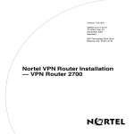
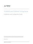
hierarchy. Figure 2-1 shows a simple network architecture with four users of
TCP/IP services: data link switching (DLSw), Telnet, FTP, and BGP.
DLSw
FTP
Telnet
BGP
TCP
IP
TCP0001A
Figure 2-1.
2-6
TCP Between IP and Clients
304234-A Rev 00
Overview of IP Utilities
The interface between TCP and programs that use TCP consists of a set of
messages exchanged between the clients and TCP, and a set of functions and
macros that user programs call to exchange TCP messages. These programs use
the functions and macros to:
•
Open, close, abort, and get the status of connections.
•
Control the flow of data.
•
Encapsulate data for TCP to transmit.
•
Process received TCP data.
When a program passes data to TCP, the TCP layer formats the data and calls on
the IP layer to transmit the data to its destination.
For information about creating TCP on the router, see Chapter 1. For information
about editing TCP parameters, see Chapter 3.
FTP Overview
The File Transfer Protocol allows files to be transferred from a server to an FTP
client or from an FTP client to the server. FTP ensures the integrity of data
transferred from one system to another.
Using FTP, you can log in to a remote host, identify yourself, list remote
directories, copy files to or from the remote host, and execute a few simple
commands remotely.
When you enable FTP on the router, you can:
•
Download files from a host system to a remote router and retrieve files from
the router.
•
Examine the directory listing of files on the remote router.
•
Delete files on the remote router.
For information about creating the FTP server on the router, see Chapter 1. For
information about editing FTP parameters, see Chapter 4.
304234-A Rev 00
2-7
Configuring IP Utilities
How FTP Works
The FTP client initiates an FTP session with the FTP server on the router. The
session establishes two separate connections between host and router as follows:
•
Control connection -- the communication path between the FTP client and the
FTP control server for the exchange of commands and replies used for
sending a command request or response.
•
Data connection -- a full-duplex connection over which data is transferred in a
specified mode and type between FTP client and FTP server.
The FTP client residing on the host and the FTP server residing on the router rely
on the underlying support of TCP and IP for the reliable, sequenced transfer of
data and control messages (Figure 2-2).
Host
Router
FTP
Client
Server
FTP
TCP
TCP
IP
IP
LAN/WAN
Key
Control connection
Data connection
TCP0002A
Figure 2-2.
2-8
FTP Client and Server
304234-A Rev 00
Overview of IP Utilities
Table 2-3 describes the FTP commands that the FTP server supports on Bay
Networks routers.
Table 2-3.
Command
FTP Commands Supported
Code
Description
Access Control Commands
User Name
USER
Initiates an FTP session for the user.
Password
PASS
Specifies a user’s encrypted identification for access control.
Logout
QUIT
Terminates the session and closes the control connection.
Transfer Parameter Commands
Data Port
PORT
Specifies the data port to be used in the data connection.
Representation
Type
TYPE
Specifies the data transfer type. The server supports transfer
of ASCII and image (binary) data.
Transfer Mode
MODE Specifies the transfer mode. The server supports stream
mode only.
File Structure
STRU
Specifies the file structure type. The server supports file (no
record) structure only.
FTP Service Commands
Retrieve
RETR
Causes the server to transfer the specified file to the client.
Abort
ABOR
Causes the server to abort the previous FTP service
command and any associated transfer of data.
Store
STOR
Causes the server to accept the data transferred over the data
connection and store it on the server.
Store Unique
STOU
Specifies the same operation as the Store command and, in
addition, causes the server to create the resulting file in the
current directory under a name unique to that directory.
Delete
DELE
Causes the server to delete the specified file on the server.
List
LIST
Causes the server to send to the client a detailed list of files.
Name List
NLST
Causes the server to send to the client a list of file names.
Status
STAT
Causes the server to send to the client the control connection
status. If the server receives the command during file transfer,
the server sends the client the status of the transfer.
Help
HELP
Provides helpful information.
No Operation
NOOP Specifies no action. Causes the server to send an OK reply.
(continued)
304234-A Rev 00
2-9
Configuring IP Utilities
Table 2-3.
Command
FTP Commands Supported (continued)
Code
Description
Change Working CWD
Directory
Causes the server to change the volume.
Print Working
Directory
Causes the server to print its current working directory.
PWD
Implementation-specific FTP Commands
Compact
COMP Causes the server to compact the flash card. Use this
command after the delete command, or when the amount of
contiguous space is low. You can determine the amount of
contiguous space on a router by using the dir command.
TFTP Overview
The Trivial File Transfer Protocol (TFTP) is a TCP/IP standard protocol for
transferring files with minimum capability and minimal overhead. TFTP is
implemented on top of the unreliable connectionless datagram delivery service
and is used to move files between network devices.
TFTP was designed to be small and easy to implement. Because it is small, it is
more restrictive, lacking most of the features of the File Transfer Protocol (FTP).
TFTP provides inexpensive, unsophisticated file-transfer service only. It cannot
list directories and provides no authentication.
TFTP runs on top of the User Datagram Protocol (UDP) and uses timeout and
retransmission to ensure that data arrives. Each file transfer begins with a request
to read or write to a file; this request also serves to ask for a connection. If the
server grants the request, the connection is opened and the file is sent in
fixed-length blocks (data packets) of 512 bytes. Each data packet contains one
block of data and must be acknowledged by an acknowledgment packet before the
next packet is sent. A data packet of less than 512 bytes terminates the transfer.
If a packet gets lost in the network, the intended recipient will time out and may
retransmit its last packet (which can be data or an acknowledgment), causing the
sender of the lost packet to retransmit the packet. Because the lock-step
acknowledgment guarantees that all older packets have been received, the sender
keeps one packet only on hand for transmission.
2-10
304234-A Rev 00
Overview of IP Utilities
Both devices involved in a TFTP transfer are senders and receivers. One device
sends data and receives acknowledgments; the other device sends
acknowledgments and receives data.
The IP router includes a client and server implementation of TFTP, enabling the
router to transmit and receive files across a network.
For information about creating TFTP on the router, see Chapter 1. For information
about editing TFTP parameters, see Chapter 5.
Telnet Overview
Telnet is a virtual terminal protocol that is part of the TCP/IP protocol suite. It
allows you to access any system on your network running the Telnet server
software. Accessing Telnet establishes a virtual connection between your terminal
and the specified host. Once you connect to a host through Telnet, your terminal
appears to be connected directly to that host.
Telnet offers three basic services:
•
It defines a network virtual terminal that provides a standard interface to
remote systems. Clients do not have to understand the details of all possible
remote systems; they are built to use the standard interface.
•
It allows client and server to negotiate options, and it provides a set of
standard options.
•
It treats both ends of the connection symmetrically. So, instead of forcing the
client side to connect to a user’s terminal, Telnet allows an arbitrary program
to become a client. Furthermore, either end of the connection can negotiate
options.
Telnet is used primarily to access the Technician Interface. You can execute
Technician Interface commands from a remote host (inbound Telnet) or originate
an outgoing Telnet session (outbound Telnet) to another Bay Networks router or
network device that accepts Telnet. You use outbound Telnet to access remote
routers when Site Manager or Simple Network Management Protocol (SNMP) is
unavailable.
304234-A Rev 00
2-11
Configuring IP Utilities
To use Telnet to access the Technician Interface, you must assign at least one IP
address to the router. The number of Telnet connections you can make to the
Technician Interface is limited only by the availability of system resources (that is,
system memory).
Note: We recommend that you establish no more than one Telnet session per
router.
Before you can enable Telnet on the router, you must first create TCP. After you
create TCP, you can create a Telnet server and Telnet client and modify their
default parameters. For information about creating TCP and Telnet on the router,
see Chapter 1. For information about modifying Telnet default parameters, see
Chapter 6.
Telnet Server
When you create a Telnet server, the router accepts inbound requests from a Telnet
client and establishes a Telnet session to the Technician Interface.
A PC with a network configuration can run a Telnet terminal emulation program
to establish a remote session on a router (Figure 2-3). In this case, the PC is
defined as a Telnet client and the router as a Telnet server.
2-12
304234-A Rev 00
Overview of IP Utilities
$
Telnet (server)
Inbound Telnet session
TCP
connection
TCP0004A
Figure 2-3.
Telnet Server
Telnet Client
When you create a Telnet client, the router sends outbound requests to a remote
host to establish a Telnet session on a remote node. After the router establishes the
Telnet session, you can access all Technician Interface commands.
If you have established a terminal/console cable connection to a router, you can
log in to the local router and use the Telnet command to establish a remote session
on a remote router (Figure 2-4). In this case, the local router is defined as the
Telnet client and the remote router as the Telnet server.
304234-A Rev 00
2-13
Configuring IP Utilities
$
Telnet (client)
Console cable
Outbound
Telnet session
Telnet (server)
TCP
connection
TCP0005A
Figure 2-4.
2-14
Telnet Client
304234-A Rev 00
Overview of IP Utilities
NTP Overview
The Network Time Protocol (NTP) synchronizes the timing of internal clocks of
various network devices across large, diverse networks to universal standard time.
NTP runs over UDP, which in turn runs over IP. The NTP protocol specification is
documented in RFC 1305.
Each device on the network contains an internal system clock that is used to
maintain accurate time for the device. The internal system clock on most local
devices is set by eye or by wristwatch to within a minute or two of the actual time
and is rarely reset at regular intervals. Many of these clocks are battery-backed
devices that use room temperature clock oscillators that can drift as much as
several seconds each day. NTP solves this problem by automatically adjusting the
time of the devices so that they are synchronized within milliseconds.
The current implementation of NTP supports only NTP client mode. In this mode,
the local NTP client, which runs on a router, accepts time information from other
remote time servers and adjusts its clock accordingly. However, the NTP local
client will not attempt to synchronize another device’s clock.
NTP Terminology
An NTP peer can be any device that runs NTP software. However, the current
implementation of NTP refers to peers as remote time servers that provide time
information to other time servers on the network and to the local NTP client. An
NTP client refers to the local network device -- in this case a router -- that accepts
time information from other remote time servers.
NTP System Implementation Model
NTP is based on a hierarchical model that consists of a local NTP client, which
runs on the router, and a number of remote time servers. The NTP client sends
requests for time information (NTP messages) to and receives time information
from one or more remote time servers. The local NTP client reviews the time
information from all available time servers and synchronizes its internal clock to
the time servers whose time is most accurate. The NTP client does not forward
time information to other devices running NTP.
304234-A Rev 00
2-15
Configuring IP Utilities
There are two types of time servers in the NTP model: primary time servers and
secondary time servers. A primary time server is directly synchronized to a
primary reference source, usually a wire or radio clock that is synchronized to a
radio station that provides a standard time service. The primary time server is the
authoritative time source in the hierarchy, meaning that it is the one true time
source to which the other NTP devices in the subnet will synchronize their
internal clocks.
A secondary time server synchronizes its time from a primary time server or from
one or more secondary time servers to form a synchronization subnet (see
Figure 2-5). A synchronization subnet is a self-organizing, hierarchical
master-slave configuration with the primary servers at the root and the secondary
servers of decreasing accuracy at successive levels from the primary servers.
Primary
server
Stratum 1
P
S
S
Secondary
servers
S
S
S
Stratum 2
Stratum 3
TCP0007A
Figure 2-5.
Time Servers Forming a Synchronization Subnet
In the NTP model, the synchronization subnet automatically reconfigures in a
hierarchical master-slave configuration to produce the most accurate and reliable
time, even when one or more primary time servers or the network path between
them fails. This includes a case in which all the primary servers on a partitioned
subnet fail, but one or more backup primary servers continue to operate. Should
all primary time servers in the subnet fail, the remaining secondary servers will
synchronize among themselves.
2-16
304234-A Rev 00
Overview of IP Utilities
How NTP Distributes Time Within the Subnet
NTP distributes time through a hierarchy of primary and secondary time servers,
with each server adopting a “stratum” (see Figure 2-5 on page 2-16). A “stratum”
defines how many NTP “hops” away a particular secondary time server is from an
authoritative time source (primary time server) in the synchronization subnet.
A “stratum 1” time server, located at the top of the hierarchy, is directly attached
to an external time source, typically a wire or radio clock; a “stratum 2” time
server receives its time via NTP from a “stratum 1” time server; a “stratum 3” time
server receives its time via NTP from a “stratum 2” time server, and so forth.
Each NTP client in the synchronization subnet chooses as its time source the
server with the lowest stratum number that it is configured to communicate with
via NTP. This strategy effectively builds a self-organizing tree of NTP speakers.
The number of strata is limited to 15 to avoid long-lived synchronization loops.
NTP tries not to synchronize to a remote time server whose time might not be
accurate. It avoids doing this in two ways. First, NTP never synchronizes to a
remote time server that is not in turn synchronized itself. Second, NTP compares
the time reported by several remote time servers, and will not synchronize to a
remote time server whose time is markedly different from the others, even if its
stratum is lower.
Synchronizing with the Best Available Time Server
Unlike other implementations of time synchronization protocols, NTP does not
attempt to synchronize the remote time server’s internal clocks to each other.
Rather, NTP achieves time synchronization by synchronizing their clocks to
universal standard time using the “best” available time source and transmission
paths to that time source.
304234-A Rev 00
2-17
Configuring IP Utilities
NTP uses the following criteria to determine the time server whose time is best:
•
Time server with the lowest stratum
•
Time server closest in proximity to the primary time server (reduces network
delays)
•
Time server offering the highest claimed precision
NTP prefers to have access to several (at least three) servers at the lower stratum
level, since it can apply an agreement algorithm to detect a problem on any part of
the time source.
NTP Modes of Operation
NTP provides three modes of operation (or associations) in which time servers
and NTP clients can communicate with each other in the synchronization subnet:
unicast client mode, broadcast client mode, and multicast client mode. Currently,
Bay Networks supports only NTP client mode.
NTP forms an association when two remote time servers exchange messages and
one or both of them create and maintain an instantiation of the router.
Unicast Client Mode
Unicast client mode is the recommended mode of operation. Use unicast client
mode to configure a set of remote time servers (or peers) for time synchronization.
You can also configure access control filters for time servers in unicast client
mode, but normally you would perform this operation in broadcast client or
multicast client mode. For more information about performing these tasks, see
Chapter 7.
When you configure a set of remote time servers (peers), NTP creates a peer list
that includes each time server’s IP address. The NTP client uses the peer list to
determine which remote time servers to query for time information. When the
NTP client queries the remote time servers, they respond with various timestamps,
along with information about their clocks, such as stratum, precision, and time
reference (Figure 2-6). The NTP client reviews the list of responses from all the
available servers and chooses one as the “best” available time source from which
to synchronize its internal clock.
2-18
304234-A Rev 00
Overview of IP Utilities
A
NTP
clients
NTP
time
servers
B
Server A
Server B
Peer list
C
TCP0006A
Figure 2-6.
NTP Time Servers Operating in Unicast Client Mode
Broadcast and Multicast Client Mode
In broadcast client and multicast client modes, the local NTP client will accept
NTP packets from every remote time server, provided that the IP destination
address of the NTP packet matches the IP broadcast address of the local NTP
client. After the NTP client receives NTP packets, it applies rules to select the
remote time server with the greatest accuracy.
In broadcast client and multicast client modes, you can restrict specific time
servers from sending NTP packets to an NTP client by configuring access control
filters. You cannot, however, configure peers in either broadcast client or multicast
client mode.
Bay Networks recommends that you use broadcast client mode and multicast
client mode when you have many clients on the network and only one remote time
server, as broadcasting reduces overall traffic volume on the network.
304234-A Rev 00
2-19
Configuring IP Utilities
NetBIOS Overview
The Network Basic Input/Output System (NetBIOS) is a session layer
communications service used by client and server applications in IBM token ring
and PC LAN networks.
NetBIOS provides applications with a programming interface for sharing services
and information across a variety of lower-layer network protocols, including IP.
Figure 2-7 shows the position of NetBIOS and IP in a simple network
architecture.
Figure 2-7.
NetBIOS over IP
There are three categories of NetBIOS services: the name service, the session
service, and the datagram service.
The NetBIOS name service allows an application to:
2-20
•
Verify that its own NetBIOS name is unique. The application issues an add
name query to NetBIOS. NetBIOS broadcasts the add name query, containing
the name. NetBIOS applications that receive the query return an add name
response or a name-in-conflict response. If no response to the query is
received after (typically) six broadcasts, the name is considered to be unique.
•
Delete a NetBIOS name that the application no longer requires.
304234-A Rev 00
Overview of IP Utilities
•
Use a server’s NetBIOS name to determine the server’s network address. The
application issues a name query request to NetBIOS, containing the target
server’s NetBIOS name. NetBIOS broadcasts the name query request. The
server that recognizes the name returns a name query response containing its
network address.
The NetBIOS session service allows an application to conduct a reliable,
sequenced exchange of messages with another application. The messages can be
up to 131,071 bytes long.
The NetBIOS datagram service allows an application to exchange datagrams with
a specific application or to broadcast datagrams to a group and receive datagrams
from the group. Datagrams allow applications to communicate without
establishing a session. When a NetBIOS application wants to send information
that does not require acknowledgment from the destination application, the
application can transmit a NetBIOS datagram.
NetBIOS in an IP Environment
The NetBIOS name service and datagram service rely on the capability of the
underlying network to broadcast name query requests to all NetBIOS applications.
In a NetBIOS over IP environment, it is the responsibility of the IP router to
ensure that the broadcast queries reach all appropriate network segments. To do
this, the router:
1. Analyzes each NetBIOS packet received on any NetBIOS interface to
determine whether the packet is a broadcast packet
2. Rebroadcasts each broadcast packet out all appropriate interfaces, except the
one on which it was received (readdressing the packet if required)
If alternate paths exist between different network segments, broadcasting loops
can occur. To prevent such loops, the router:
1. Stamps the data portion of the IP packet with the IP address of the router from
which the packet was rebroadcast
2. Parses the IP addresses included in the data portion of the IP packet to
determine if the packet has already been rebroadcast by that router
In Figure 2-8, for example, client C on the network connected to router B wishes
to communicate with server S, which is located on the network connected to
router A.
304234-A Rev 00
2-21
Configuring IP Utilities
The following steps occur:
1. The client issues a name query request to NetBIOS on the host, specifying the
server application by its NetBIOS name. The IP service on the host broadcasts
the name query request.
2. Router B receives the name query request, determines that it is a broadcast
message, and rebroadcasts it out each of its NetBIOS interfaces (except for
the one on which it arrived).
3. Router A receives the broadcast request and rebroadcasts it to its local
network.
4. The server on router A receives the IP broadcast request and recognizes its
own name.
Router A
s
c
Router B
Router C
Router D
Key
c
Client
Server
s
NetBIOS/IP Interface
IP0033A
Figure 2-8.
2-22
Broadcasting a Name Query Request
304234-A Rev 00
Overview of IP Utilities
The server responds to the name query request by issuing a positive name query
response, containing the IP address of the server, to NetBIOS on the host. The
following steps occur (Figure 2-9):
1. NetBIOS sends the response to router A as a unicast message.
2. Router A and router B forward the unicast response to the awaiting client.
Now that the client has obtained the server’s IP address from the name query
response, client and server can communicate by exchanging IP messages.
Router A
s
c
Router B
Router C
Router D
Key
c
Client
Server
s
NetBIOS/IP Interface
IP0034A
Figure 2-9.
304234-A Rev 00
Returning a Unicast Name Query Response
2-23
Configuring IP Utilities
Forwarding Name Queries over an Unnumbered Interface
NetBIOS cannot be configured directly on an unnumbered interface. Because of
this restriction, name query requests cannot be broadcast over an unnumbered
interface.
To forward name query requests over unnumbered interfaces, the network
administrator configures a static NetBIOS name entry to the proper NetBIOS
name server. In this way, name query requests will traverse the unnumbered
interfaces as unicast IP packets.
DNS Overview
The Domain Name System (DNS) is a distributed database system, with DNS
clients requesting host name/address resolution information from various DNS
servers. DNS is used with numerous types of networking applications and
protocols.
Specifically, DNS provides a directory service that allows client devices to
retrieve information from a server-based database. For the Internet, DNS enables
a device to obtain the IP address of a host based on the host’s domain name.
The Bay Networks router functions as a DNS client.
DNS Proxy Server
The DNS proxy server is a system solution that lets the router act as a DNS server.
DNS clients can configure an IP interface on the router as their DNS server. The
DNS proxy server on the router has a list of DNS servers to contact on behalf of
the client.
Using the DNS proxy server feature, a network administrator can statically
configure hosts to use the IP address of the DNS proxy server on the router. If the
DNS servers change or physically move, the administrator has to change only the
list of DNS servers on the router, rather than having to make the change on each
individual client.
2-24
304234-A Rev 00
Overview of IP Utilities
How the DNS Proxy Server Works
Clients on a LAN typically use DNS servers to resolve a host name to an IP
address. For example, a client might request the service,
“www.baynetworks.com”. Since the client cannot connect to a name service, it
must translate this name to an IP address so that it can communicate over the
network. DNS is the mechanism that resolves the host name to an IP address.
Clients are typically configured with a list of DNS name servers to contact to
resolve host names. Due to network infrastructure changes, Internet service
providers and network administrators often change the IP addresses of these
statically configured name servers. When the IP addresses of these name servers
change, every network client must change its local configuration for the IP address
of the new name servers. Using a DNS proxy server minimizes the work for the
system administrator. Each client uses the IP address of the DNS proxy server
instead of the true DNS servers. The DNS proxy server contains the list of real
name servers. If the DNS servers change, only the server list on the DNS proxy
server must change, not every client.
Typically, a network client has a default route specified to a local attached router.
Careful network planning can allow the DNS proxy server to be the same as this
default route. Setting up the DNS proxy server this way simplifies the task for a
network administrator, who does not need to know the list of DNS servers when
configuring new clients.
By default, the DNS proxy listens on UDP port 53 (standard DNS server port) for
the IP interface on which it is configured. (You can, however, configure a different
port number.) When the DNS proxy receives a valid request, it forwards the packet
to the DNS server on the proxy’s list. Once the DNS proxy server receives a
response from the DNS server, the DNS proxy forwards the packet to the
requesting client and puts the response into its local cache.
The DNS proxy lets you configure timeout intervals and the number of
retransmissions allowed. If the first DNS server contacted times out, the DNS
proxy tries the next server on the list, and so on, until it receives a response. If all
the servers time out, the DNS proxy returns a serv_fail error to the client. You can
configure up to three DNS servers per proxy interface.
DNS responses can contain several answers to the client question, although most
DNS clients use only the first answer in the list. Optionally, you can configure the
DNS proxy to truncate the number of answers returned to the client. Any answers
beyond the maximum are omitted from the DNS response message.
304234-A Rev 00
2-25
Configuring IP Utilities
How the DNS Cache Works
The DNS proxy caches DNS records to improve performance, reduce network
traffic, and free the real DNS server from repetitive requests. As with standard
DNS, entries expire based on the time-to-live (TTL) field in the DNS record. You
can configure the maximum number of cache entries. The default is 20.
When the DNS proxy receives a request, it searches its cache for the current
request. If an entry exists, the DNS proxy immediately returns the answer to the
client. If it does not find the entry, the DNS proxy sends a request to the real DNS
server. When the response comes back from the DNS server and the TTL is
greater than 0, the DNS proxy inserts the response into the cache and returns the
response to the client.
2-26
304234-A Rev 00
Chapter 3
Customizing TCP Services
This chapter describes how to customize TCP services on the router. It assumes
you have configured IP on an interface and started TCP using the default
parameters, as described in Chapter 1, and that you understand the TCP concepts
described in Chapter 2.
After you start TCP on the router, TCP default values are in effect for all TCP
parameters. You customize TCP by modifying these parameters as described in
the following sections.
304234-A Rev 00
Topic
Page
Configuring TCP Using the BCC or Site Manager
3-2
Disabling and Reenabling TCP
3-3
Setting the Minimum Retransmission Timeout
3-3
Setting the Maximum Retransmission Timeout
3-5
Setting the Maximum Window Size
3-6
3-1
Configuring IP Utilities
Configuring TCP Using the BCC or Site Manager
Table 3-1 lists the TCP configuration tasks described in this chapter and indicates
whether you can use the BCC or Site Manager to perform each task.
Table 3-1.
TCP Configuration Tasks
Task
BCC
Site Manager
Disabling and Reenabling TCP
✓
✓
Setting the Minimum Retransmission Timeout
✓
✓
Setting the Maximum Retransmission Timeout
✓
✓
Setting the Maximum Window Size
✓
✓
Disabling and Reenabling TCP
After you configure IP and start TCP, all TCP default parameters are
automatically enabled on the router. If you disable TCP, it is no longer available
on all IP circuits.
Using the BCC
To disable TCP, navigate to the TCP prompt and enter:
disable
For example, the following command line disables TCP on the router.
tcp# disable
tcp#
To reenable TCP, navigate to the TCP prompt and enter:
enable
For example, this command line reenables TCP on the router.
tcp# enable
tcp#
3-2
304234-A Rev 00
Customizing TCP Services
Using Site Manager
Complete the tasks in the following table to disable and reenable TCP on the
router.
Site Manager Procedure
You do this
System responds
1. In the Configuration Manager window,
choose Protocols.
The Protocols menu opens.
2. Choose Global Protocols.
The Global Protocols menu opens.
3. Choose TCP.
The TCP menu opens.
4. Choose Global.
The Edit TCP Global Parameters window
opens.
5. Set the Enable/Disable parameter. Click
on Help or see the parameter description
on page A-4.
6. Click on OK.
Site Manager saves your changes and
exits the window.
Setting the Minimum Retransmission Timeout
You can specify a minimum value for the retransmission timeout. When one side
of a TCP connection sends a frame and does not receive an acknowledgment from
the other side of the connection within the timeout period, the sending station
retransmits the frame.
If you are transmitting on a high-speed network and you set the minimum
retransmission timeout value too high, network performance may degrade because
TCP must wait for the timeout period to elapse before retransmitting
unacknowledged data.
304234-A Rev 00
3-3
Configuring IP Utilities
Using the BCC
By default, the router sets the minimum retransmission timeout value to 250
milliseconds (ms).
To specify a value for the minimum retransmission timeout, navigate to the TCP
prompt and enter:
min-rto <integer>
integer is a value from 100 to 15,000 milliseconds (ms).
For example, the following command sets the value for the minimum
retransmission timeout to 300 ms:
tcp# min-rto 300
tcp#
Note: When specifying a value for the Minimum Retransmission Timeout
parameter, do not use a comma in the value.
Using Site Manager
Complete the tasks in the following table to specify a value for the minimum
retransmission timeout.
Site Manager Procedure
You do this
System responds
1. In the Configuration Manager window,
choose Protocols.
The Protocols menu opens.
2.
The Global Protocols menu opens.
Choose Global Protocols.
3. Choose TCP.
The TCP menu opens.
4. Choose Global.
The Edit TCP Global Parameters window
opens.
5. Set the Min. Retransmission Timeout
(msec.) parameter. Click on Help or see
the parameter description on page A-2.
6. Click on OK.
3-4
Site Manager saves your changes and
exits the window.
304234-A Rev 00
Customizing TCP Services
Setting the Maximum Retransmission Timeout
You can specify a maximum value for the retransmission timeout. When one side
of a TCP connection sends a frame and does not receive an acknowledgment from
the other side of the connection within the timeout period, the sending station
retransmits the frame.
If you are transmitting on a low-speed network and you set the maximum
retransmission timeout value too low, the network may become congested, as TCP
retransmits unacknowledged frames that have not yet reached their destination.
Using the BCC
By default, TCP sets the maximum retransmission value to 240,000 ms. To
specify a value for the minimum retransmission timeout, navigate to the TCP
prompt and enter:
max-rto <integer>
integer is a value from 15,000 to 240,000 ms.
For example, the following command sets the value for the maximum
retransmission timeout to 235,000 ms:
tcp# max-rto 235000
tcp#
Note: When specifying a value for the Maximum Retransmission Timeout
parameter, do not use a comma in the value.
304234-A Rev 00
3-5
Configuring IP Utilities
Using Site Manager
Complete the tasks in the following table to specify a maximum value for the
retransmission timeout.
Site Manager Procedure
You do this
System responds
1. In the Configuration Manager window,
choose Protocols.
The Protocols menu opens.
2.
The Global Protocols menu opens.
Choose Global Protocols.
3. Choose TCP.
The TCP menu opens.
4. Choose Global.
The Edit TCP Global Parameters window
opens.
5. Set the Max. Retransmission Timeout
(msec.) parameter. Click on Help or see
the parameter description on page A-3.
6. Click on OK.
Site Manager saves your changes and
exits the window.
Setting the Maximum Window Size
You can specify a value in bytes to determine the maximum transmit-and-receive
window size that TCP allows for each connection. The larger the window size, the
more memory each TCP connection consumes.
Using the BCC
By default, TCP sets the maximum window size to 4,096 bytes. To specify the
maximum window size, navigate to the TCP prompt and enter:
max-win <integer>
integer is a value from 512 to 65,535 bytes.
For example, the following command sets the value for the maximum window
size to 1,050 bytes:
tcp# max-win 1050
tcp#
3-6
304234-A Rev 00
Customizing TCP Services
Note: When specifying a value for the Maximum Window Size parameter, do
not use a comma in the value.
Using Site Manager
Complete the tasks in the following table to set the maximum window size (in
bytes) that TCP allows for each connection.
Site Manager Procedure
You do this
System responds
1. In the Configuration Manager window,
choose Protocols.
The Edit TCP Global Parameters window
opens.
2.
The Global Protocols menu opens.
Choose Global Protocols.
3. Choose TCP.
The TCP menu opens.
4. Choose Global.
The Edit TCP Global Parameters window
opens.
5. Set the Max. Window Size (bytes)
parameter. Click on Help or see the
parameter description on page A-3.
6. Click on OK.
304234-A Rev 00
Site Manager saves your changes and
exits the window.
3-7
Chapter 4
Customizing FTP Services
This chapter describes how to customize FTP services on the router. It assumes
you have configured IP on an interface and started FTP using the default
parameters, as described in Chapter 1, and that you understand the FTP concepts
described in Chapter 2.
After you start FTP on the router, FTP default values are in effect for all FTP
parameters. You customize FTP by modifying these parameters as described in the
following sections.
304234-A Rev 00
Topic
Page
Configuring FTP Using the BCC or Site Manager
4-2
Disabling and Reenabling FTP
4-2
Specifying the Number of Login Retries
4-5
Specifying the Maximum FTP Idle Timeout
4-6
Specifying the Maximum Number of FTP Sessions
4-7
Specifying the Data Transmission Type
4-8
Specifying the FTP Control Connection
4-8
Specifying a Data Transfer Value
4-9
Specifying the TCP Window Size
4-10
4-1
Configuring IP Utilities
Configuring FTP Using the BCC or Site Manager
Table 4-1 lists the FTP configuration tasks described in this chapter and indicates
whether you can use the BCC or Site Manager to perform each task.
Table 4-1.
FTP Configuration Tasks
Task
BCC
Site Manager
Disabling and Reenabling FTP
✓
✓
Specifying the FTP Default Volume
✓
✓
Specifying the Number of Login Retries
✓
✓
Specifying the Maximum FTP Idle Timeout
✓
✓
Specifying the Maximum Number of FTP Sessions
✓
✓
Specifying the Data Transmission Type
✓
Specifying the FTP Control Connection
✓
Specifying a Data Transfer Value
✓
Specifying the TCP Window Size
✓
✓
Disabling and Reenabling FTP
After you configure IP and start FTP, all FTP default values are automatically
enabled on the router.
Using the BCC
To disable FTP, navigate to the FTP prompt and enter:
disable
For example, this command line disables the FTP server on the router.
ftp# disable
ftp#
To reenable FTP, navigate to the FTP prompt and enter:
enable
4-2
304234-A Rev 00
Customizing FTP Services
For example, the following command line reenables FTP on the router.
ftp# enable
ftp#
Using Site Manager
Complete the tasks in the following table to enable and disable an FTP server.
Site Manager Procedure
You do this
System responds
1. In the Configuration Manager window,
choose Protocols.
The Protocols menu opens.
2. Choose Global Protocols.
The Global Protocols menu opens.
3. Choose FTP.
The FTP menu opens.
4. Choose Global.
The Edit FTP Global Parameters window
opens.
5. Set the Enable/Disable parameter. Click
on Help or see the parameter description
on page A-4.
6. Click on OK.
Site Manager saves your changes and
exits the window.
Specifying the FTP Default Volume
The FTP default volume is the file system volume to which FTP writes transferred
files and from which FTP retrieves files for transfer. To specify the FTP default
volume, you must enter a value from 1 to 13 for the file system volume. On
diskette-based systems, you must enter volume A as the default volume.
Using the BCC
By default, FTP uses volume 1 as the default volume. To specify a volume,
navigate to the FTP prompt and enter:
default-volume <volume_number>
volume _number is an integer ranging from 1 to 14, 1a to 4a, or 1b to 4b.
304234-A Rev 00
4-3
Configuring IP Utilities
For example, the following command sequence specifies volume 5 as the default
volume and displays attributes and values:
ftp# default-volume 5
ftp# info
on box
state disabled
default-volume 2
login-retries 3
idle-timeout 900
max-sessions 3
tcp-window-size 60000
Using Site Manager
Complete the tasks in the following table to specify the FTP default volume.
Site Manager Procedure
You do this
System responds
1. In the Configuration Manager window,
choose Protocols.
The Protocols menu opens.
2. Choose Global Protocols.
The Global Protocols menu opens.
3. Choose FTP.
The FTP menu opens.
4. Choose Global.
The Edit FTP Global Parameters window
opens.
5. Set the Default Volume parameter. Click
on Help or see the parameter description
on page A-4.
6. Click on OK.
4-4
Site Manager saves your changes and
exits the window.
304234-A Rev 00
Customizing FTP Services
Specifying the Number of Login Retries
The FTP login retries value is the number of FTP login retries that FTP will accept
before rejecting logins.
Using the BCC
By default, FTP accepts only three FTP login retries. To change the number of
retries, navigate to the FTP prompt and enter:
login-retries <integer>
integer is the number of retries that FTP allows.
For example, the following command line causes FTP to accept 10 login retries
before rejecting logins:
ftp# login-retries 10
ftp#
Using Site Manager
Complete the tasks in the following table to specify an FTP login retry value.
Site Manager Procedure
You do this
System responds
1. In the Configuration Manager window,
choose Protocols.
The Protocols menu opens.
2. Choose Global Protocols.
The Global Protocols menu opens.
3. Choose FTP.
The FTP menu opens.
4. Choose Global.
The Edit FTP Global Parameters window
opens.
5. Set the Login Retries parameter. Click on
Help or see the parameter description on
page A-4.
6. Click on OK.
304234-A Rev 00
Site Manager saves your changes and
exits the window.
4-5
Configuring IP Utilities
Specifying the Maximum FTP Idle Timeout
The FTP idle time is the length of time (in seconds) that FTP waits before closing
an idle FTP control connection. You must determine the maximum idle time you
want to allow and specify the time value in seconds.
Using the BCC
By default, FTP waits 900 seconds before closing an idle FTP control connection.
To specify a timeout interval, navigate to the FTP prompt and enter:
idle-timeout <integer>
integer is the number of seconds FTP waits before timing out.
For example, the following command line causes FTP to wait 150 seconds before
closing an idle FTP control session:
ftp# idle-timeout 150
ftp#
Using Site Manager
Complete the tasks in the following table to set the length of time (in seconds) that
FTP waits before closing an idle FTP control connection.
Site Manager Procedure
You do this
System responds
1. In the Configuration Manager window,
choose Protocols.
The Protocols menu opens.
2. Choose Global Protocols.
The Global Protocols menu opens.
3. Choose FTP.
The FTP menu opens.
4. Choose Global.
The Edit FTP Global Parameters window
opens.
5. Set the Idle Time Out (secs) parameter.
Click on Help or see the parameter
description on page A-5.
6. Click on OK.
4-6
Site Manager saves your changes and
exits the window.
304234-A Rev 00
Customizing FTP Services
Specifying the Maximum Number of FTP Sessions
You can determine the maximum number of FTP sessions you want to run
simultaneously by specifying a value from 1 to 10000.
Using the BCC
By default, FTP allows up to three sessions at one time. To specify the number of
sessions, navigate to the FTP prompt and enter:
max-sessions <integer>
integer is the maximum number of allowable FTP sessions.
For example, the following command sets the maximum number of FTP sessions
to 10:
ftp# max-session 10
ftp#
Using Site Manager
Complete the tasks in the following table to specify the maximum number of FTP
sessions you want to run at one time.
Site Manager Procedure
You do this
System responds
1. In the Configuration Manager window,
choose Protocols.
The Protocols menu opens.
2. Choose Global Protocols.
The Global Protocols menu opens.
3. Choose FTP.
The FTP menu opens.
4. Choose Global.
The Edit FTP Global Parameters window
opens.
5. Set the Max. Sessions parameter. Click
on Help or see the parameter description
on page A-5.
6. Click on OK.
304234-A Rev 00
Site Manager saves your changes and
exits the window.
4-7
Configuring IP Utilities
Specifying the Data Transmission Type
You can determine the type of data transmission you want to use to transfer your
files. To tranfer files consisting of ASCII characters, specify ASCII. To specify
files consisting of binary characters, specify Binary.
You can use Site Manager to specify the data transmission type you want to use.
Site Manager Procedure
You do this
System responds
1. In the Configuration Manager window,
select Protocols.
The Protocols menu opens.
2. Choose Global Protocols.
The Global Protocols menu opens.
3. Choose FTP.
The FTP menu opens.
4. Choose Global.
The Edit FTP Global Parameters window
opens.
5. Set the Type of Service parameter. Click
on Help or see the parameter description
on page A-5.
6. Click on OK.
Site Manager saves your changes and
exits the window.
Specifying the FTP Control Connection
You can determine how the Internet transport layer handles datagrams on a control
data connection by specifying the Type of Service value that FTP inserts in IP
datagrams on a control connection.
You can use Site Manager to specify the type of service value.
Site Manager Procedure
You do this
System responds
1. In the Configuration Manager window,
choose Protocols.
The Protocols menu opens.
2. Choose Global Protocols.
The Global Protocols menu opens.
(continued)
4-8
304234-A Rev 00
Customizing FTP Services
Site Manager Procedure (continued)
You do this
System responds
3. Choose FTP.
The FTP menu opens.
4. Choose Global.
The Edit FTP Global Parameters window
opens.
5. Set the Control Connection parameter.
Click on Help or see the parameter
description on page A-6.
6. Click on OK.
Site Manager saves your changes and
exits the window.
Specifying a Data Transfer Value
You can determine how the Internet transport layer handles datagrams on a data
transfer connection by specifying a value that indicates the Type of Service that
FTP inserts in IP datagrams on a data transfer connection.
You can use Site Manager to specify the type of service value that FTP inserts in
IP datagrams on a data transfer connection.
Site Manager Procedure
You do this
System responds
1. In the Configuration Manager window,
select Protocols.
The Protocols menu opens.
2. Choose Global Protocols.
The Global Protocols menu opens.
3. Choose FTP.
The FTP menu opens.
4. Choose Global.
The Edit FTP Global Parameters window
opens.
5. Set the Data Transfer parameter. Click on
Help or see the parameter description on
page A-6.
6. Click on OK.
304234-A Rev 00
Site Manager saves your changes and
exits the window.
4-9
Configuring IP Utilities
Specifying the TCP Window Size
You can determine the size of the window you require on your system for TCP
connections by specifying its size in bytes.
Using the BCC
By default, the size of TCP windows used for connections is 60,000 bytes. To
specify a TCP window size, navigate to the FTP prompt and enter:
tcp-window-size <integer>
integer is the size in bytes of the TCP window.
For example, the following command line sets the window size used for TCP
connections to 45,000 bytes:
ftp# tcp-window-size 45000
ftp#
Using Site Manager
Complete the tasks in the following table to specify the size of the windows used
for TCP connections.
Site Manager Procedure
You do this
System responds
1. In the Configuration Manager window,
choose Protocols.
The Protocols menu opens.
2. Choose Global Protocols.
The Global Protocols menu opens.
3. Choose FTP.
The FTP menu opens.
4. Choose Global.
The Edit FTP Global Parameters window
opens.
5. Set the TCP Window Size parameter.
Click on Help or see the parameter
description on page A-6.
6. Click on OK.
4-10
Site Manager saves your changes and
exits the window.
304234-A Rev 00
Chapter 5
Customizing TFTP Services
This chapter describes how to customize Trivial File Transfer Protocol (TFTP)
services on the router. It assumes you have configured IP on an interface and
started TFTP using the default parameters, as described in Chapter 1, and that you
understand the TFTP concepts described in Chapter 2.
After you start TFTP on the router, TFTP default values are in effect for all TFTP
parameters. You customize TFTP by modifying these parameters as described in
the following sections.
304234-A Rev 00
Topic
Page
Configuring TFTP Using the BCC or Site Manager
5-2
Disabling and Reenabling TFTP Services
5-2
Specifying the Default Volume for the Router
5-3
Specifying a Retry Timeout Value
5-4
Specifying a Close Timeout Value
5-5
Specifying the Number of Retransmissions
5-6
5-1
Configuring IP Utilities
Configuring TFTP Using the BCC or Site Manager
Table 5-1 lists the TFTP configuration tasks described in this chapter and
indicates whether you can use the BCC or Site Manager to perform each task.
Table 5-1.
TFTP Configuration Tasks
Task
BCC
Site Manager
Disabling and Reenabling TFTP Services
✓
✓
Specifying the Default Volume for the Router
✓
✓
Specifying a Retry Timeout Value
✓
✓
Specifying a Close Timeout Value
✓
✓
Specifying the Number of Retransmissions
✓
✓
Disabling and Reenabling TFTP Services
After you configure IP and start TFTP on the router, all TFTP default parameters
are automatically enabled on the router.
Using the BCC
To disable TFTP, navigate to the TFTP prompt and enter:
disable
For example, the following command line disables TFTP on the router.
tftp# disable
tftp#
To reenable TFTP, navigate to the TFTP prompt and enter:
enable
For example, the following command line reenables TFTP on the router.
tftp# enable
tftp#
5-2
304234-A Rev 00
Customizing TFTP Services
Using Site Manager
To disable and reenable TFTP services, perform the following actions:
Site Manager Procedure
You do this
System responds
1. In the Configuration Manager window,
choose Protocols.
The Protocols menu opens.
2. Choose IP.
The IP menu opens.
3. Choose TFTP.
The Edit TFTP Parameters window
opens.
4. Set the Enable parameter. Click on Help
or see the parameter description on
page A-7.
The field is selected.
5. Click on OK.
You return to the Configuration Manager
window.
Specifying the Default Volume for the Router
When you configure a router, you must specify which of the router’s slots will be
used, by default, for all TFTP GETs and PUTs.
Using the BCC
By default, the slot on which TFTP runs on the router is slot 2. If you are
configuring an AN® router, you must specify slot 1.
To specify the slot on which TFTP runs, navigate to the TFTP prompt and enter:
default-volume <slot>
slot is an integer in the range 1 to 14, 1a to 4a, or 1b to 4b.
For example, the following command line sets the default volume on which TFTP
runs to 3:
tftp# default-volume 3
tftp#
304234-A Rev 00
5-3
Configuring IP Utilities
Using Site Manager
Complete the tasks in the following table to specify the appropriate volume
number on which you are configuring TFTP.
Site Manager Procedure
You do this
System responds
1. In the Configuration Manager window,
choose Protocols.
The Protocols menu opens.
2. Choose IP.
The IP menu opens.
3. Choose TFTP.
The Edit TFTP Parameters window
opens.
4. Set the Default Volume parameter. Click
on Help or see the parameter description
on page A-7.
5. Click on OK.
Site Manager saves your changes and
exits the window.
Specifying a Retry Timeout Value
You can specify the amount of time (in seconds) that TFTP waits for an
acknowledgment before retransmitting the last packet.
Using the BCC
By default, TFTP waits 5 seconds for an acknowledgment before retransmitting
the last packet.
To specify a retry timeout value, navigate to the TFTP prompt and enter:
retry-timeout <integer>
integer is any number of seconds.
For example, the following command line causes TFTP to wait 10 seconds before
it transmits the last packet:
tftp# retry-timeout 10
tftp#
5-4
304234-A Rev 00
Customizing TFTP Services
Using Site Manager
Complete the tasks in the following table to specify the number of seconds that
TFTP waits for an acknowledgment.
Site Manager Procedure
You do this
System responds
1. In the Configuration Manager window,
choose Protocols.
The Protocols menu opens.
2. Choose IP.
The IP menu opens.
3. Choose TFTP.
The Edit TFTP Parameters window
opens.
4. Set the Retry Time Out parameter. Click
on Help or see the parameter description
on page A-7.
5. Click on OK.
Site Manager saves your changes and
exits the window.
Specifying a Close Timeout Value
You can specify the number of seconds TFTP waits, after it has successfully
retrieved a file, to make sure that the sender has received the last acknowledgment.
By default, TFTP waits 25 seconds.
Using the BCC
To specify a retry timeout value, navigate to the TFTP prompt and enter:
close-timeout <integer>
integer is any number of seconds.
For example, the following command line causes TFTP to wait 15 seconds to
make sure that the sender has received the last acknowledgment:
tftp# close-timeout 15
tftp#
304234-A Rev 00
5-5
Configuring IP Utilities
Using Site Manager
Complete the tasks in the following table to specify a close timeout value.
Site Manager Procedure
You do this
System responds
1. In the Configuration Manager window,
choose Protocols.
The Protocols menu opens.
2. Choose IP.
The IP menu opens.
3. Choose TFTP.
The Edit TFTP Parameters window
opens.
4. Set the Close Time Out parameter. Click
on Help or see the parameter description
on page A-8.
5. Click on OK.
Site Manager saves your changes and
exits the window.
Specifying the Number of Retransmissions
You can specify the number of times TFTP retransmits an unacknowledged
message before abandoning the transfer attempt.
Using the BCC
By default, TFTP abandons the transfer attempt after five unsuccessful
retransmissions. To specify the number of times TFTP retransmits an
unacknowledged message before aborting, navigate to the TFTP prompt and
enter:
retry-count <integer>
integer indicates any number of retransmissions.
For example, the following command line causes TFTP to abandon the transfer
attempt after 10 retries:
tftp# retry-count 10
tftp#
5-6
304234-A Rev 00
Customizing TFTP Services
Using Site Manager
Complete the tasks in the following table to specify the number of retransmissions
that TFTP will attempt.
Site Manager Procedure
You do this
System responds
1. In the Configuration Manager window,
choose Protocols.
The Protocols menu opens.
2. Choose IP.
The IP menu opens.
3. Choose TFTP.
The Edit TFTP Parameters window
opens.
4. Set the Retransmit parameter. Click on
Help or see the parameter description on
page A-8.
5. Click on OK.
304234-A Rev 00
Site Manager saves your changes and
exits the window.
5-7
Chapter 6
Customizing Telnet Services
This chapter describes how to customize Telnet services on the router. It assumes
you have configured IP on an interface and started Telnet using the default
parameters, as described in Chapter 1, and that you understand the Telnet concepts
described in Chapter 2.
After you start Telnet services on the router, default values are in effect for all
Telnet configuration parameters. You may want to change these parameter values,
depending on the requirements of your network.
304234-A Rev 00
Topic
Page
Configuring Telnet Using the BCC or Site Manager
6-2
Customizing the Telnet Configuration
6-3
Customizing the Telnet Server on the Router
6-6
Configuring a Telnet Client on the Router
6-20
6-1
Configuring IP Utilities
Configuring Telnet Using the BCC or Site Manager
Table 6-1 lists the Telnet configuration tasks described in this chapter and
indicates whether you can use the BCC or Site Manager to perform each task.
Table 6-1.
Telnet Configuration Tasks
Task
BCC
Site Manager
Changing the Name of the Manager’s Login Script File
✓
✓
Changing the Name of the User’s Login Script File
✓
✓
Enabling and Disabling User Logout
✓
✓
Disabling and Reenabling a Telnet Server on the IP
Router
✓
✓
Specifying the Maximum Number of Lines on the
Console
✓
✓
Pausing Telnet Console Output
✓
✓
Changing the Telnet Login Prompt
✓
✓
Changing the Login Timeout
✓
✓
Changing the Password Timeout
✓
✓
Changing the Command Timeout
✓
✓
Changing Login Retries
✓
✓
✓
Using Telnet Server Diagnostics
6-2
Changing the History File
✓
✓
Disabling and Reenabling a Telnet Client on the IP
Router
✓
✓
Enabling and Disabling Verbose Debug Logging
✓
✓
Changing the Remote Port
✓
✓
Changing the Command Prompt
✓
✓
304234-A Rev 00
Customizing Telnet Services
Customizing the Telnet Configuration
After you start the Telnet server to establish inbound Telnet sessions on the router,
the script files for the Manager’s Login, User’s Login, and Force User’s Login run
automatically when you log in. You can accept these defaults or customize the
Telnet configuration by changing these scripts as needed.
Changing the Name of the Manager’s Login Script File
By default, the name of the manager’s script file is automgr.bat. You can specify a
new name for the manager’s login script by supplying an 8-character file name. If
you do not want to change the name of the manager’s login script, accept the
default name.
Using the BCC
To specify the name of the Manager’s Login script, navigate to the server-specific
prompt and enter:
manager-script <string>
string is the name of the manager’s login script file.
For example, the following command line causes the device to assign the name
manager1.bat to the manager’s login script:
server# manager-script manager1.bat
server#
304234-A Rev 00
6-3
Configuring IP Utilities
Using Site Manager
Complete the tasks in the following table to specify a new manager’s login script
file.
Site Manager Procedure
You do this
System responds
1. In the Configuration Manager window,
choose Protocols.
The Protocols menu opens.
2. Choose Global Protocols.
The Global Protocols menu opens.
3. Choose Telnet Server.
The Telnet Server menu opens.
4. Choose Global.
The Telnet Configuration window opens.
5. Set the Manager’s Login Script
parameter. Click on Help or see the
parameter description on page A-13.
6. Click on OK.
Site Manager saves your changes, exits
the window, and returns you to the
Configuration Manager window.
Changing the Name of the User’s Login Script File
By default, the name of the user’s login script file is autouser.bat. You can specify
a new name for the user’s login script file by supplying an 8-character file name. If
you do not want to change the name of the user’s login script, accept the default
name.
Using the BCC
To specify the name of the user’s login script file, navigate to the server-specific
prompt and enter:
auto-user-script <string>
string is the name of the user’s login script file.
For example, the following command line causes the system to automatically
execute the script file router1.bat at login:
server# auto-user-script router1.bat
server#
6-4
304234-A Rev 00
Customizing Telnet Services
Using Site Manager
Complete the tasks in the following table to specify a new user’s login script file.
Site Manager Procedure
You do this
System responds
1. In the Configuration Manager window,
choose Protocols.
The Protocols menu opens.
2. Choose Global Protocols.
The Global Protocols menu opens.
3. Choose Telnet Server.
The Telnet Server menu opens.
4. Choose Global.
The Telnet Configuration window opens.
5. Set the User’s Login Script parameter.
Click on Help or see the parameter
description on page A-13.
6. Click on OK.
Site Manager saves your changes and
exits the window.
Enabling and Disabling User Logout
By default, the user autoscript is in effect for your Telnet session when you log in.
You can press control-c to cancel the user autoscript and access the Technician
Interface. To prevent users from canceling the user autoscript at login, set this
parameter to Enable.
Using the BCC
To prevent users from canceling the user autoscript at login, navigate to the
server-specific prompt and enter:
force-logout enabled
For example, this command line prevents users from canceling the user autoscript
at login:
server# force-logout enabled
server#
To allow users to cancel the user autoscript at login, navigate to the server-specific
prompt and enter:
force-logout disabled
304234-A Rev 00
6-5
Configuring IP Utilities
For example, this command line allows users to cancel the user autoscript at login:
server# force-logout disabled
server#
Using Site Manager
Complete the tasks in the following table to cancel the user autoscript at login or
to prevent users from canceling the user autoscript at login.
Site Manager Procedure
You do this
System responds
1. In the Configuration Manager window,
choose Protocols.
The Protocols menu opens.
2. Choose Global Protocols.
The Global Protocols menu opens.
3. Choose Telnet Server.
The Telnet Server menu opens.
4. Choose Global.
The Telnet Configuration window opens.
5. Set the Force User Logout parameter.
Click on Help or see the parameter
description on page A-14.
6. Click on OK.
Site Manager saves your changes and
exits the window.
Customizing the Telnet Server on the Router
This section describes how to customize your Telnet server on the router.
Disabling and Reenabling a Telnet Server on the IP Router
You can enable or disable a Telnet server on the IP router. By default, Telnet is
enabled for the IP router, allowing you to establish Telnet sessions to the target
router.
Using the BCC
By default, the Telnet server is enabled on the IP router. To disable a Telnet server,
navigate to the Telnet server prompt and enter:
disable
6-6
304234-A Rev 00
Customizing Telnet Services
For example:
telnet# server
server# disable
To reenable a Telnet server on the IP router, navigate to the Telnet server prompt
and enter:
enable
For example:
telnet# server
server# enable
Using Site Manager
Complete the tasks in the following table to enable or disable a Telnet server on an
IP router.
Site Manager Procedure
You do this
System responds
1. In the Configuration Manager window,
choose Protocols.
The Protocols menu opens.
2. Choose Global Protocols.
The Global Protocols menu opens.
3. Choose Telnet Server.
The Telnet Server menu opens.
4. Choose Global.
The Telnet Server Global Parameters
window opens.
5. Set the Enable/Disable parameter. Click
on Help or see the parameter description
on page A-15.
6. Click on OK.
304234-A Rev 00
Site Manager saves your changes and
exits the window.
6-7
Configuring IP Utilities
Specifying the Maximum Number of Lines on the Console
You can specify the maximum number of lines displayed on the Telnet console
screen. The screen may override the number of lines you specify if Telnet can
negotiate the window size with the remote client. Make sure that the number that
you set is in accordance with your console requirements.
Using the BCC
By default, the maximum number of lines displayed on the Telnet screen is 24. To
specify the maximum number of lines displayed on the Telnet screen, enter:
lines <integer>
integer is the maximum number of lines that the console screen can display.
For example, the following command line sets the maximum number of lines
displayed on a Telnet console screen to 50:
server# lines 50
server#
Using Site Manager
Complete the tasks in the following table to specify the maximum number of lines
displayed on a Telnet console screen.
Site Manager Procedure
You do this
System responds
1. In the Configuration Manager window,
choose Protocols.
The Protocols menu opens.
2. Choose Global Protocols.
The Global Protocols menu opens.
3. Choose Telnet Server.
The Telnet Server menu opens.
4. Choose Global.
The Telnet Server Global Parameters
window opens.
5. Set the TI Lines per Screen parameter.
Click on Help or see the parameter
description on page A-9.
6. Click on OK.
6-8
Site Manager saves your changes and
exits the window.
304234-A Rev 00
Customizing Telnet Services
Pausing Telnet Console Output
By default, Telnet console output pauses after each screen fills with data. You can
configure Telnet not to pause after each screen fills with data by disabling this
feature.
Using the BCC
To configure the Telnet console output to pause, navigate to the Telnet-specific
prompt and enter:
more
For example, the following command line prevents Telnet console output from
pausing:
server# more disabled
server#
Using Site Manager
Complete the tasks in the following table to specify whether to pause Telnet
console output.
Site Manager Procedure
You do this
System responds
1. In the Configuration Manager window,
choose Protocols.
The Protocols menu opens.
2. Choose Global Protocols.
The Global Protocols menu opens.
3. Choose Telnet Server.
The Telnet Server menu opens.
4. Choose Global.
The Telnet Server Global Parameters
window opens.
5. Set the TI More parameter. Click on Help
or see the parameter description on
page A-9.
6. Click on OK.
304234-A Rev 00
Site Manager saves your changes and
exits the window.
6-9
Configuring IP Utilities
Changing the Telnet Login Prompt
You can change the Telnet login prompt on the Telnet console screen by
specifying a character string from 1 through 18 alphanumeric characters.
Using the BCC
To change the Telnet login prompt on the Telnet console screen, navigate to the
server-specific prompt and enter:
prompt <string>
string is any text string from 1 to 18 characters.
For example, the following command line changes the Telnet login prompt to rtr1:
server# prompt rtr1
server#
Using Site Manager
Complete the tasks in the following table to change the Telnet login prompt on the
Telnet console screen.
Site Manager Procedure
You do this
System responds
1. In the Configuration Manager window,
choose Protocols.
The Protocols menu opens.
2. Choose Global Protocols.
The Global Protocols menu opens.
3. Choose Telnet Server.
The Telnet Server menu opens.
4. Choose Global.
The Telnet Server Global Parameters
window opens.
5. Set the TI Prompt parameter. Click on
Help or see the parameter description on
page A-10.
6. Click on OK.
6-10
Disconnects the current Telnet session.
304234-A Rev 00
Customizing Telnet Services
Changing the Login Timeout
You can specify a value that will determine the number of minutes that can elapse
before the device disconnects the Telnet session if you fail to enter a login ID at
the login prompt.
Using the BCC
By default, the device waits 1 minute before it disconnects the Telnet session if
you fail to enter a login ID at the login prompt. To specify the number of minutes
that can elapse before the device disconnects the Telnet session if you fail to enter
a login ID at the login prompt, navigate to the server-specific prompt and enter:
login-timeout
For example, the following command line causes the device to wait 15 minutes
before it disconnects the Telnet session if you fail to enter a login ID at the login
prompt:
server# login-timeout 15
server#
Using Site Manager
Complete the tasks in the following table to specify the number of minutes that
can elapse before the device disconnects the Telnet session.
Site Manager Procedure
You do this
System responds
1. In the Configuration Manager window,
choose Protocols.
The Protocols menu opens.
2. Choose Global Protocols.
The Global Protocols menu opens.
3. Choose Telnet Server.
The Telnet Server menu opens.
4. Choose Global.
The Telnet Server Global Parameters
window opens.
5. Set the Login Timeout (min.) parameter.
Click on Help or see the parameter
description on page A-10.
6. Click on OK.
304234-A Rev 00
Site Manager saves your changes and
exits the window.
6-11
Configuring IP Utilities
Changing the Password Timeout
By changing the password timeout value you can determine the number of
minutes that can elapse before the device disconnects the Telnet session if you do
not enter a password at the password prompt.
Using the BCC
By default, the device waits 1 minute before it disconnects the Telnet session if
you fail to enter a password at the password prompt. To specify the number of
minutes that can elapse before the device disconnects the Telnet session, navigate
to the server-specific prompt and enter:
password-timeout <integer>
integer is a number from 1 to 99.
For example, the following command causes the device to wait 20 minutes before
it disconnects the Telnet session:
server# password-timeout 20
server#
Using Site Manager
Complete the tasks in the following table to specify the number of minutes that
can elapse before the device disconnects the Telnet session if you fail to enter a
password.
Site Manager Procedure
You do this
System responds
1. In the Configuration Manager window,
choose Protocols.
The Protocols menu opens.
2. Choose Global Protocols.
The Global Protocols menu opens.
3. Choose Telnet Server.
The Telnet Server menu opens.
4. Choose Global.
The Telnet Server Global Parameters
window opens.
(continued)
6-12
304234-A Rev 00
Customizing Telnet Services
Site Manager Procedure (continued)
You do this
System responds
5. Set the Password Timeout (min.)
parameter. Click on Help or see the
parameter description on page A-10.
6. Click on OK.
Site Manager saves your changes and
exits the window.
Changing the Command Timeout
By changing the command timeout you determine the number of minutes that can
elapse before the Technician Interface disconnects the Telnet session if you do not
enter a command at the command prompt.
Using the BCC
By default, the device waits 15 minutes before it disconnects the Telnet session if
you fail to enter a command at the command prompt. To specify the number of
minutes that the device will wait before it disconnects the Telnet session, navigate
to the server-specific prompt and enter:
command-timeout <integer>
integer is a number from 1 to 99.
For example, the following command line causes the device to wait 35 minutes
before it disconnects the Telnet session if you fail to enter a command at the
command prompt:
server# command-timeout 35
server#
304234-A Rev 00
6-13
Configuring IP Utilities
Using Site Manager
Complete the tasks in the following table to specify the number of minutes that
can elapse before the device disconnects the Telnet session if you fail to enter a
command.
Site Manager Procedure
You do this
System responds
1. In the Configuration Manager window,
choose Protocols.
The Protocols menu opens.
2. Choose Global Protocols.
The Global Protocols menu opens.
3. Choose Telnet Server.
The Telnet Server menu opens.
4. Choose Global.
The Telnet Server Global Parameters
window opens.
5. Set the Command Timeout (min.)
parameter. Click on Help or see the
parameter description on page A-11.
6. Click on OK.
Site Manager saves your changes and
exits the window.
Changing Login Retries
By changing the login retries you can determine the maximum number of login
attempts allowed before the device disconnects the Telnet session.
Using the BCC
By default, the device allows you 3 login attempts before it disconnects the Telnet
session. To change the maximum number of allowed login attempts, enter:
login-retries <integer>
integer is a number from 1 to 99 login attempts.
For example, the following command line tells the device to allow 10 attempts
before it disconnects the Telnet session:
server# login-retries 10
server#
6-14
304234-A Rev 00
Customizing Telnet Services
Using Site Manager
Complete the tasks in the following table to specify the number of login attempts
allowed before the device disconnects the Telnet session.
Site Manager Procedure
You do this
System responds
1. In the Configuration Manager window,
choose Protocols.
The Protocols menu opens.
2. Choose Global Protocols.
The Global Protocols menu opens.
3. Choose Telnet Server.
The Telnet Server menu opens.
4. Choose Global.
The Telnet Server Global Parameters
window opens.
5. Set the Login Retries parameter. Click on
Help or see the parameter description on
page A-11.
6. Click on OK.
Site Manager saves your changes and
exits the window.
Using Telnet Server Diagnostics
This section describes how to configure Telnet server diagnostic parameters to
customize the way the Technician Interface performs diagnostics on a router. Field
Service personnel use these features to troubleshoot problems.
The BCC does not support these functions.
Enabling Diagnostic Reporting
This parameter allows field personnel to specify whether the Technician Interface
displays a report that shows a record of all processing operations. By default,
recording of processing operations is disabled.
304234-A Rev 00
6-15
Configuring IP Utilities
To enable the Technician Interface to display a report showing a record of all
processing operations, complete the tasks in the following table.
Site Manager Procedure
You do this
System responds
1. In the Configuration Manager window,
choose Protocols.
The Protocols menu opens.
2. Choose Global Protocols.
The Global Protocols menu opens.
3. Choose Telnet Server.
The Telnet Server menu opens.
4. Choose Global.
The Telnet Server Global Parameters
window opens.
5. Set the Diagnostic Report parameter.
Click on Help or see the parameter
description on page A-11.
6. Click on OK.
Site Manager saves your changes and
exits the window.
Enabling Diagnostic Exercise
This parameter allows field personnel to enable exercise diagnostics on the Telnet
server.
To enable exercise diagnostics on the Telnet server, complete the tasks in the
following table:
Site Manager Procedure
You do this
System responds
1. In the Configuration Manager window,
choose Protocols.
The Protocols menu opens.
2. Choose Global Protocols.
The Global Protocols menu opens.
3. Choose Telnet Server.
The Telnet Server menu opens.
4. Choose Global.
The Telnet Server Global Parameters
window opens.
(continued)
6-16
304234-A Rev 00
Customizing Telnet Services
Site Manager Procedure (continued)
You do this
System responds
5. Set the Diagnostic Exercise parameter.
Click on Help or see the parameter
description on page A-12.
6. Click on OK.
Site Manager saves your changes and
exits the window.
Enabling Diagnostic Network Data
This parameter allows you to specify whether you want the Technician Interface
to display Telnet protocol information. It is used for diagnostic purposes only by
field service personnel.
To display Telnet protocol information, complete the tasks in the following table.
Site Manager Procedure
You do this
System responds
1. In the Configuration Manager window,
choose Protocols.
The Protocols menu opens.
2. Choose Global Protocols.
The Global Protocols menu opens.
3. Choose Telnet Server.
The Telnet Server menu opens.
4. Choose Global.
The Telnet Server Global Parameters
window opens.
5. Set the Diagnostic Network Data
parameter. Click on Help or see the
parameter description on page A-12.
6. Click on OK.
304234-A Rev 00
Site Manager saves your changes and
exits the window.
6-17
Configuring IP Utilities
Enabling Diagnostic PTY Data
To specify whether you want the Technician Interface to display pseudo-terminal
driver (PTY) information, complete the tasks in the following table.
Site Manager Procedure
You do this
System responds
1. In the Configuration Manager window,
choose Protocols.
The Protocols menu opens.
2. Choose Global Protocols.
The Global Protocols menu opens.
3. Choose Telnet Server.
The Telnet Server menu opens.
4. Choose Global.
The Telnet Server Global Parameters
window opens.
5. Set the Diagnostic PTY Data parameter.
Click on Help or see the parameter
description on page A-12.
6. Click on OK.
Site Manager saves your changes and
exits the window.
Enabling Diagnostic Options
To specify whether you want the Technician Interface to display information on
Telnet diagnostic options, complete the tasks in the following table.
Site Manager Procedure
You do this
System responds
1. In the Configuration Manager window,
choose Protocols.
The Protocols menu opens.
2. Choose Global Protocols.
The Global Protocols menu opens.
3. Choose Telnet Server.
The Telnet Server menu opens.
4. Choose Global.
The Telnet Server Global Parameters
window opens.
5. Set the Diagnostic Options parameter.
Click on Help or see the parameter
description on page A-13.
6. Click on OK.
6-18
Site Manager saves your changes and
exits the window.
304234-A Rev 00
Customizing Telnet Services
Changing the History File
You can determine the maximum number of commands you want stored in the
local command history table. The table stores each command you enter at the
device prompt, on a first-in, first-out (FIFO) basis.
Using the BCC
By default, the number of commands that the router stores in the local command
history table is 20. To set the maximum number of commands that you want the
router to store in the history table, navigate to the server prompt and enter:
hist <integer>
integer is a number from 1 to 40.
For example, the following command line sets the maximum number of
commands that the router stores in the history table to 35:
server# hist 35
server#
Using Site Manager
Complete the tasks in the following table to specify the number of commands that
the router stores in the history table.
Site Manager Procedure
You do this
System responds
1. In the Configuration Manager window,
choose Protocols.
The Protocols menu opens.
2. Choose Global Protocols.
The Global Protocols menu opens.
3. Choose Telnet Server.
The Telnet Server menu opens.
4. Choose Global.
The Telnet Server Global Parameters
window opens.
5. Set the TI History Depth parameter. Click
on Help or see the parameter description
on page A-14.
6. Click on OK.
304234-A Rev 00
Site Manager saves your changes and
exits the window.
6-19
Configuring IP Utilities
Configuring a Telnet Client on the Router
After you start a Telnet client on the router for outbound Telnet sessions, as
described in Chapter 1, default values are in effect for all Telnet client parameters.
You may want to change these parameter values, depending on the requirements
of your network.
The following sections describe information you supply and options you select
that affect the way a Telnet client runs on the router.
Disabling and Reenabling a Telnet Client on the IP Router
You can disable or reenable a Telnet client on the IP router. By default, the Telnet
client is enabled on the IP router, allowing you to establish Telnet sessions to the
target router.
Using the BCC
To disable a Telnet client, navigate to the client-specific prompt and enter:
disable
For example, the following command line disables a Telnet client:
client# disable
client#
To reenable a Telnet client on the IP router and display its default values, navigate
to the client-specific prompt and enter:
enable
For example, the following command line reenables a Telnet client:
client# enable
client# info
on telnet
state enabled
debug-log-flag off
remote-port 23
prompt ()
6-20
304234-A Rev 00
Customizing Telnet Services
Using Site Manager
Complete the tasks in the following table to enable or disable a Telnet client on an
IP router.
Site Manager Procedure
You do this
System responds
1. In the Configuration Manager window,
choose Protocols.
The Protocols menu opens.
2. Choose Global Protocols.
The Global Protocols menu opens.
3. Choose Telnet Client.
The Telnet Client menu opens.
4. Choose Global.
The Telnet Client Global Parameters
window opens.
5. Set the Enable/Disable parameter. Click
on Help or see the parameter description
on page A-8.
6. Click on OK.
Site Manager saves your changes and
exits the window.
Enabling and Disabling Verbose Debug Logging
You can specify whether you want to enable or disable verbose debug logging.
When you enable verbose debug logging, you tell the device to display the
negotiation process between the Telnet server and Telnet client. This parameter is
for diagnostic use only.
Using the BCC
By default, verbose debug logging is turned off (disabled). To enable verbose
debug logging, navigate to the client-specific prompt and enter:
debug-log-flag on
For example, the following command line enables verbose debug logging:
client# debug-log-flag on
client#
304234-A Rev 00
6-21
Configuring IP Utilities
To disable verbose debug logging, navigate to the client-specific prompt and enter:
client# debug-log-flag off
client#
Site Manager
To enable and disable verbose debug logging, complete the tasks in the following
table.
Site Manager Procedure
You do this
System responds
1. In the Configuration Manager window,
choose Protocols.
The Protocols menu opens.
2. Choose Global Protocols.
The Global Protocols menu opens.
3. Choose Telnet Client.
The Telnet Client menu opens.
4. Choose Global.
The Edit Telnet Client Global Parameters
window opens.
5. Set the Verbose Debug Logging
parameter. Click on Help or see the
parameter description on page A-15.
6. Click on OK.
You return to the Configuration Manager
window.
Changing the Remote Port
You can change the default remote Telnet server’s TCP remote port by specifying
a valid TCP port number.
Using the BCC
By default, the Telnet server’s TCP remote port is 23. To change the remote port,
navigate to the client-specific prompt and enter:
remote-port <integer>
integer is any valid TCP port number.
6-22
304234-A Rev 00
Customizing Telnet Services
For example, the following command line changes the Telnet server’s TCP remote
port number to 20:
client# remote-port 20
client#
Using Site Manager
To change the remote Telnet server’s TCP port, complete the tasks in the
following table.
Site Manager Procedure
You do this
System responds
1. In the Configuration Manager window,
choose Protocols.
The Protocols menu opens.
2. Choose Global Protocols.
The Global Protocols menu opens.
3. Choose Telnet Client.
The Telnet Client menu opens.
4. Choose Global.
The Edit Telnet Client Global Parameters
window opens.
5. Set the Remote Port parameter. Click on
Help or see the parameter description on
page A-16.
6. Click on OK.
You return to the Configuration Manager
window.
Changing the Command Prompt
You can change the default Telnet client command prompt by specifying any text
string less than 40 characters long.
Using the BCC
To change the default Telnet client command prompt, navigate to the
client-specific prompt and enter:
prompt <string>
string is any text string less than 40 characters.
304234-A Rev 00
6-23
Configuring IP Utilities
For example, the following command line changes the default command prompt
to system1:
client# prompt system1
client#
Using Site Manager
To change the default Telnet client command prompt, complete the tasks in the
following table.
Site Manager Procedure
You do this
System responds
1. In the Configuration Manager window,
choose Protocols.
The Protocols menu opens.
2. Choose Global Protocols.
The Global Protocols menu opens.
3. Choose Telnet Client.
The Telnet Client menu opens.
4. Choose Global.
The Edit Telnet Client Global Parameters
window opens.
5. Set the Prompt parameter. Click on Help
or see the parameter description on
page A-16.
6. Click on OK.
6-24
You return to the Configuration Manager
window.
304234-A Rev 00
Chapter 7
Customizing NTP Services
This chapter describes how to customize NTP services on the router. It assumes
you have configured IP on an interface and started NTP using the default
parameters, as described in Chapter 1, and that you understand the NTP concepts
described in Chapter 2.
After you start NTP on the router, NTP default values are in effect for all NTP
parameters. You customize NTP by modifying these parameters as described in
the following sections.
304234-A Rev 00
Topic
Page
Configuring NTP Using the BCC or Site Manager
7-2
Disabling and Reenabling NTP
7-2
Setting the NTP Operation Mode
7-3
Configuring Remote Time Servers
7-5
Configuring NTP Access Control
7-13
7-1
Configuring IP Utilities
Configuring NTP Using the BCC or Site Manager
Table 7-1 lists the NTP configuration tasks described in this chapter and indicates
whether you can use the BCC or Site Manager to perform each task.
Table 7-1.
NTP Configuration Tasks
Task
BCC
Site Manager
Disabling and Reenabling NTP
✓
✓
✓
Setting the NTP Operation Mode
Adding Remote Time Servers
✓
✓
Setting the Mode for a Remote Time Server
✓
✓
✓
Setting Local Host Mode
Specifying the Source IP Address
✓
✓
Specifying Peer Preference
Deleting Remote Time Servers from a Router
✓
✓
Configuring NTP Access Control
✓
✓
Disabling and Reenabling NTP
By default, NTP is enabled when you start it on the router. You can disable and
reenable NTP at any time.
Using the BCC
To disable NTP services, navigate to the NTP prompt and enter:
disable
For example, the following command line disables NTP on the router:
ntp# disable
ntp#
To reenable NTP services, navigate to the NTP prompt and enter:
enable
7-2
304234-A Rev 00
Customizing NTP Services
For example, the following command line reenables NTP on the router:
ntp# enable
ntp#
Using Site Manager
To disable and reenable NTP on the router, complete the tasks in the following
table.
Site Manager Procedure
You do this
System responds
1. In the Configuration Manager window,
choose Protocols.
The Protocols menu opens.
2. Choose Global Protocols.
The Global Protocols menu opens.
3. Choose NTP.
The NTP menu opens.
4. Choose Global.
The Edit NTP Global Parameters window
opens.
5. Set the Enable/Disable parameter. Click
on Help or see the parameter description
on page A-2.
6. Click on OK.
You return to the Configuration Manager
window.
Setting the NTP Operation Mode
You must specify the mode of operation in which you want to configure NTP to
run on a router. NTP provides three operation modes: unicast client, broadcast
client, and multicast client modes. The current implementation of NTP supports
only client mode.
You select unicast client mode when you want to configure remote time servers
(peers). You select broadcast client mode and multicast client mode when you
want to configure access control filters to restrict certain remote time servers from
sending NTP packets to a local NTP client.
By default, NTP runs in unicast client mode.
304234-A Rev 00
7-3
Configuring IP Utilities
To specify the mode in which you want NTP to run on the router, complete the
tasks in the following table.
Site Manager Procedure
You do this
System responds
1. In the Configuration Manager window,
choose Protocols.
The Protocols menu opens.
2. Choose Global Protocols.
The Global Protocols menu opens.
3. Choose NTP.
The NTP menu opens.
4. Choose Global.
The Edit NTP Global Parameters window
opens.
5. Set the Mode parameter. Click on Help or
see the parameter description on page
A-17.
6. Click on OK.
7-4
You return to the Configuration Manager
window.
304234-A Rev 00
Customizing NTP Services
Configuring Remote Time Servers
You configure remote time servers (peers) for time synchronization in unicast
client mode only. Configuring a remote time server involves:
•
Adding remote time servers
•
Specifying the configuration peer mode for the time server
•
Setting the mode of operation of the router
•
Specifying a source IP address for the time server
•
Specifying peer preference
•
Deleting peers
Adding Remote Time Servers
You add remote time servers to the router by specifying the IP address of each
time server (peer). NTP adds the IP address of the time server to a peer list, which
the local NTP client uses when querying remote time servers for time information.
NTP queries all the remote time servers in the peer list for time information and
then determines which time server to synchronize its internal clock to based on the
following criteria:
•
Lowest stratum
•
Closest in proximity to the primary time server
•
Claimed highest precision
When the local NTP client queries the remote time servers from the peer list, the
servers respond with various timestamps, along with information about their
clocks, such as stratum, precision, and time reference. The local NTP client
reviews a list of responses from all the available servers and chooses one server as
the “best” time source from which to synchronize its internal clock.
Bay Networks recommends that you configure a minimum of three upper stratum
remote time servers (peers) for a router, because it can apply an agreement
algorithm to detect a problem on any part of the time source. You can, if
necessary, add a maximum of five remote time servers on a device (a router, for
example). Configuring multiple remote time servers ensures redundancy in case
one peer fails.
304234-A Rev 00
7-5
Configuring IP Utilities
Using the BCC
To specify the IP address of each peer that you want to add to the router, navigate
to the NTP prompt and enter:
peer <address>
address is 0.0.0.0 or any valid IP address.
For example, the following command line adds the peer 2.2.2.2 to the router:
ntp# peer 2.2.2.2
peer/2.2.2.2#
Using Site Manager
Complete the tasks in the following table to specify the IP address of each NTP
time server you want to add.
Site Manager Procedure
You do this
System responds
1. In the Configuration Manager window,
choose Protocols.
The Protocols menu opens.
2. Choose Global Protocols.
The Global Protocols menu opens.
3. Choose NTP.
The NTP menu opens.
4. Choose Peers.
The NTP Peers Configuration List window
opens.
5. Click on Add.
The NTP Peer Configuration window
opens.
6. Set the Peer IP address parameter. Click
on Help or see the parameter descriptions
on page A-17.
7. Click on OK.
7-6
The NTP Peer Configuration List window
opens, displaying the IP address of the
time server that you configured and the
default NTP peer configuration parameter
values.
304234-A Rev 00
Customizing NTP Services
Setting the Mode for a Remote Time Server
You can specify the mode in which a remote time server operates on the network.
However, because NTP operates locally in client mode only, all remote time
servers known to the local NTP client are servers.
By default, the mode is set to server, indicating that the local NTP client adjusts its
clock to the given remote time server but does not attempt to adjust the time
server’s clock. You should accept the default value.
Using the BCC
To specify the mode in which a remote time server operates, enter:
mode <mode_type>
mode_type is either server or peer.
For example, the following command line sets the mode in which the remote
server 3.3.3.3 will operate to server.
peer/3.3.3.3# mode server
peer/3.3.3.3# info
on ntp
address 3.3.3.3
mode server
src-ip-address 0.0.0.0
Using Site Manager
To specify the mode for the remote time server, complete the tasks in the
following table.
Site Manager Procedure
You do this
System responds
1. In the Configuration Manager window,
choose Protocols.
The Protocols menu opens.
2. Choose Global Protocols.
The Global Protocols menu opens.
3. Choose NTP.
The NTP menu opens.
4. Choose Peers.
The NTP Peers Configuration List window
opens.
(continued)
304234-A Rev 00
7-7
Configuring IP Utilities
Site Manager Procedure (continued)
You do this
System responds
5. Click on the IP address of the time server
in the NTP Peer list.
6. Set the Config Peer Mode parameter.
Click on Help or see the parameter
descriptions on page A-18.
7. Click on Apply.
Site Manager sets the mode for the
remote time server to Server. Bay
Networks supports only the Server
option.
8. Click on Done.
You return to the Configuration Manager
window.
Setting Local Host Mode
Local Host Mode indicates the mode of operation of the local NTP client. By
default, the Local Host Mode is set to client, because only unicast client mode is
supported.
To specify the local mode in which you want to configure the local NTP client,
complete the tasks in the following table.
Site Manager Procedure
You do this
System responds
1. In the Configuration Manager window,
choose Protocols.
The Protocols menu opens.
2. Choose Global Protocols.
The Global Protocols menu opens.
3. Choose NTP.
The NTP menu opens.
4. Choose Peers.
The NTP Peers Configuration List window
opens.
5. Click on the IP address of the time server
in the NTP Peer list.
6. Set the Local Host Mode parameter. Click
on Help or see the parameter descriptions
on page A-19.
(continued)
7-8
304234-A Rev 00
Customizing NTP Services
Site Manager Procedure (continued)
You do this
System responds
7. Click on Apply.
Site Manager sets the mode to Client.
Bay Networks supports only the Client
option.
8. Click on Done.
You return to the Configuration Manager
window.
Specifying the Source IP Address
The source IP address allows you to specify a single IP address that NTP uses to
override the source address of the IP interface from which the NTP packet is
transmitted. Use this parameter only when you want the remote time server to
filter NTP timestamps for the local NTP client based on IP source address. You
should using a circuitless IP address as the source IP address.
You might also want to specify a source IP address when you have enabled
security features on a time server and you want to restrict access to it.
Using the BCC
By default, the source IP address is 0.0.0.0. To specify a source IP address that
overrides the source address of the IP interface from which the NTP packet is
transmitted, enter:
src-ip-address <address>
For example, the following command line causes NTP to use the source IP
address 4.4.4.4 to override the IP interface source address:
peer/3.3.3.3# src-ip-address 4.4.4.4
peer/3.3.3.3#
304234-A Rev 00
7-9
Configuring IP Utilities
Using Site Manager
To specify the source IP address of a remote time server, complete the tasks in the
following table.
Site Manager Procedure
You do this
System responds
1. In the Configuration Manager window,
choose Protocols.
The Protocols menu opens.
2. Choose Global Protocols.
The Global Protocols menu opens.
3. Choose NTP.
The NTP menu opens.
4. Choose Peers.
The NTP Peers Configuration List window
opens.
5. Click on the IP address of the time server
that appears in the NTP Peer list.
6. Set the Source IP Address parameter.
Click on Help or see the parameter
descriptions on page A-19.
7. Click on Apply.
NTP uses the source IP address that you
specify to override the source address of
the interface from which the NTP packet
is transmitted.
8. Click on Done.
You return to the Configuration Manager
window.
Specifying Peer Preference
The Peer Preference parameter allows you to specify a list of remote time servers
(peers) that are preferred by the local NTP client above and beyond the criteria for
selecting peers (stratum setting, closest, and claimed higher precision).
By default, the Peer Preference option value is set to No. This means that the local
NTP client rejects packets from the remote time server.
You can enable peer preference for a remote time server by changing the Peer
Preference option value to Yes. This means that the local NTP client prefers
(accepts) packets from the remote server and synchronizes its internal clock to this
server.
7-10
304234-A Rev 00
Customizing NTP Services
Complete the tasks in the following table to specify whether the local NTP client
will prefer or reject NTP packets from the remote time server.
Site Manager Procedure
You do this
System responds
1. In the Configuration Manager window,
choose Protocols.
The Protocols menu opens.
2. Choose Global Protocols.
The Global Protocols menu opens.
3. Choose NTP.
The NTP menu opens.
4. Choose Peers.
The NTP Peers Configuration List window
opens.
5. Click on the IP address of the time server
that displays in the NTP Peer list.
6. Set the Peer Preference parameter. Click
on Help or see the parameter descriptions
on page A-20.
7. Click on Apply.
When you select Yes, the local NTP client
prefers (accepts) NTP packets from the
remote time server and synchronizes its
internal clock to it.
When you select No, the local NTP client
rejects packets from the remote time
server.
8. Click on Done.
304234-A Rev 00
You return to the Configuration Manager
window.
7-11
Configuring IP Utilities
Deleting Remote Time Servers from a Router
When you delete a remote time server (peer), NTP deletes the IP address of that
time server from the NTP peer list.
Using the BCC
To delete a remote time server (peer), navigate to the peer-specific prompt and
enter:
delete
For example, the following command line deletes the time server 3.3.3.3:
peer/3.3.3.3# delete
ntp#
Using Site Manager
To delete remote time servers from a router, complete the tasks in the following
table.
Site Manager Procedure
You do this
System responds
1. In the Configuration Manager window,
choose Protocols.
The Protocols menu opens.
2. Choose Global Protocols.
The Global Protocols menu opens.
3. Choose NTP.
The NTP menu opens.
4. Choose Peers.
The NTP Peers Configuration List window
opens.
5. Click on the IP address of the time server
that you want to delete from the NTP Peer
list.
7-12
6. Click on Delete.
The IP address for the time server you
selected is removed from the NTP Peer
list.
7. Click on Done.
You return to the Configuration Manager
window.
304234-A Rev 00
Customizing NTP Services
Configuring NTP Access Control
The access control feature allows you to selectively restrict NTP clients from
accepting NTP timestamps from specific remote time servers on the network by
filtering these timestamps based on the source IP address or an IP subnet address.
This is similar to an inbound filter that drops NTP packets based on source IP
address and IP subnet mask.
Configuring NTP access control for a time server involves:
•
Specifying the IP address of the remote time server
•
Specifying a filter type
•
Specifying an IP subnet mask
Specifying the IP Address of the Time Server
When you specify the IP address of the remote time server whose access to the
local NTP client you want to restrict, NTP adds the IP address of the time server to
an access control list, which the local NTP client uses when querying remote time
servers for time information. Use the access control option when operating in
broadcast client and multicast client mode.
To specify the IP address of the remote time server whose access to the local NTP
client you want to restrict, complete the tasks in the following table.
Site Manager Procedure
You do this
System responds
1. In the Configuration Manager window,
select Protocols.
The Protocols menu opens.
2. Choose Global Protocols.
The Global Protocols menu opens.
3. Choose NTP.
The NTP menu opens.
4. Choose Access.
The NTP Access Configuration List
window opens.
5. Click on Add.
The NTP Access Configuration window
opens.
(continued)
304234-A Rev 00
7-13
Configuring IP Utilities
Site Manager Procedure (continued)
You do this
System responds
6. Set the Access IP Address parameter.
Click on Help or see the parameter
descriptions on page A-17.
7. Click on OK.
The source IP address of the remote time
server whose access you want to restrict
appears in the NTP Access Configuration
List window.
Specifying a Filter Type and IP Subnet Mask
The NTP filter type parameter allows you to specify whether to drop or accept
NTP timestamps destined for a local NTP client. By default, the filter type is set to
Restrict, which tells NTP to drop specific NTP timestamps destined for a local
NTP client based on its source IP address and source subnet mask.
For example, if you have 10 remote time servers broadcasting to a router and you
want to receive NTP timestamps from only three remote time servers, you can
restrict the other seven remote time servers.
When you set the Filter Type to Prefer, the local NTP client accepts packets
received from remote time servers.
The Mask parameter allows you to specify an IP subnet mask address to filter
NTP timestamps based on a source subnet.
Using Site Manager
Complete the tasks in the following table to add access control to a time server.
Site Manager Procedure
You do this
System responds
1. In the Configuration Manager window,
choose Protocols.
The Protocols menu opens.
2. Choose Global Protocols.
The Global Protocols menu opens.
3. Choose NTP.
The NTP menu opens.
(continued)
7-14
304234-A Rev 00
Customizing NTP Services
Site Manager Procedure (continued)
You do this
System responds
4. Choose Access.
The NTP Access Configuration List
window opens, displaying the IP address
of each time server.
5. Click on the IP address of the time server
whose access you want to restrict.
6. Set the following parameters:
• Filter Type
• Access IP Mask
Click on Help or see the parameter
descriptions on page A-18.
The Filter Type Selection box opens.
7. Click on Apply.
8. Click on Done.
You return to the Configuration Manager
window.
Deleting Access for a Time Server
When you delete access for a remote time server (peer), Site Manager removes the
IP address of the time server whose access you restricted from the access control
list.
304234-A Rev 00
7-15
Chapter 8
Customizing NetBIOS over IP
This chapter describes how to customize NetBIOS over IP services on the router.
It assumes you have configured IP on an interface and started NetBIOS using the
default parameters, as described in Chapter 1, and that you understand the
NetBIOS over IP concepts described in Chapter 2.
After you start NetBIOS over IP on the router, default values are in effect for all
NetBIOS parameters. You customize NetBIOS over IP by modifying these
parameters as described in the following sections.
304234-A Rev 00
Topic
Page
Disabling and Reenabling NetBIOS
8-2
Specifying a TTL Value for a Rebroadcast Packet
8-2
Enabling the Insertion of Record Route Option
8-3
Configuring a NetBIOS Cache
8-4
Customizing NetBIOS on an IP Interface
8-10
Configuring a Static NetBIOS Name and Address
8-13
Adding a Traffic Filter to a NetBIOS Interface
8-14
8-1
Configuring IP Utilities
Disabling and Reenabling NetBIOS
When you start NetBIOS on the router, NetBIOS is automatically enabled.
To disable or reenable NetBIOS over IP, complete the following tasks:
Site Manager Procedure
You do this
System responds
1. In the Configuration Manager window,
Choose Protocols.
The Protocols menu opens.
2. Choose IP.
The IP menu opens.
3. Choose NetBIOS.
The NetBIOS menu opens.
4. Choose Global.
The Edit NetBIOS/IP Global Parameters
window opens.
5. Set the Enable/Disable parameter. Click
on Help or see the parameter description
on page A-24.
6. Click on OK.
You return to the Configuration Manager
window.
Specifying a TTL Value for a Rebroadcast Packet
The TTL value restricts the number of routers a rebroadcast packet can traverse.
To prevent NetBIOS broadcast packets from traversing the network indefinitely,
set the parameter to a minimal value.
By default, NetBIOS sets the TTL value in each packet to 5. You can use Site
Manager to set a TTL value from 1 to 255.
Site Manager Procedure
You do this
System responds
1. In the Configuration Manager window,
Choose Protocols.
The Protocols menu opens.
2. Choose IP.
The IP menu opens.
3. Choose NetBIOS.
The NetBIOS menu opens.
(continued)
8-2
304234-A Rev 00
Customizing NetBIOS over IP
Site Manager Procedure (continued)
You do this
System responds
4. Choose Global.
The Edit NetBIOS/IP Global Parameters
window opens.
5. Set the Rebroadcast Packet TTL
parameter. Click on Help or see the
parameter description on page A-23.
6. Click on OK.
Site Manager returns you to the
Configuration Manager window.
Enabling the Insertion of Record Route Option
The Insertion of Record Route option prevents rebroadcast packets from looping
forever by allowing the NetBIOS entity in the router to determine whether it has
received this packet before on this interface. If so, the router drops it.
By default, the NetBIOS Insertion of Record Route option in rebroadcast packets
is disabled. If all IP entities support this option, enable it on the router. You can
use Site Manager to enable the option.
Site Manager Procedure
You do this
System responds
1. In the Configuration Manager window,
Choose Protocols.
The Protocols menu opens.
2. Choose IP.
The IP menu opens.
3. Choose NetBIOS.
The NetBIOS menu opens.
4. Choose Global.
The Edit NetBIOS/IP Global Parameters
window opens.
5. Set the Rebroadcast Record Route
parameter. Click on Help or see the
parameter description on page A-24.
6. Click on OK.
304234-A Rev 00
Site Manager returns you to the
Configuration Manager window.
8-3
Configuring IP Utilities
Configuring a NetBIOS Cache
NetBIOS is a broadcast-intensive protocol. Much of the broadcast overhead is
related to maintaining unique names across the network and providing end users
with access to NetBIOS applications. The amount of overhead grows with the
number of NetBIOS resources (applications, servers, and clients) on the network.
To keep broadcast traffic to a minimum, each router that runs NetBIOS over IP
builds and maintains a cache of NetBIOS name/IP address pairs, using
information contained in the name query responses it receives and forwards.
In Figure 2-9 on page 2-23, for example:
1. Router A receives a name query response from the server. The router gleans
from the name query response the name and IP address of the server.
2. The router stores the name and IP address of the server in its cache.
3. The router forwards the name query response.
Routers that support NetBIOS must analyze each name query request received on
a NetBIOS interface to determine whether the name of the requested resource
(typically, a server) is in the cache. If so, the router replaces the broadcast address
in the request with the unicast IP address of the server. The router then forwards
the name query request to the server.
Enabling Name Caching on the Router
NetBIOS name caching enables the router to cache the name associated with each
NetBIOS server that is active on the network.
By default, NetBIOS name caching is disabled. You can use Site Manager to
enable name caching.
The 15-character NetBIOS name-caching parameter enables the router to treat a
NetBIOS name as either a 15- or a 16-character entity.
8-4
304234-A Rev 00
Customizing NetBIOS over IP
By default, NetBIOS treats a name as a 16-character entity. You can use Site
Manager to enable the feature if you want NetBIOS to treat a name as a
15-character entity.
Site Manager Procedure
You do this
System responds
1. In the Configuration Manager window,
choose Protocols.
The Protocols menu opens.
2. Choose IP.
The IP menu opens.
3. Choose NetBIOS.
The NetBIOS menu opens.
4. Choose Global.
The Edit NetBIOS/IP Global Parameters
window opens.
5. Set the following parameters:
• NetBIOS Name Caching
• 15-Character NetBIOS Name
Caching
Click on Help or see the parameter
description on page A-25.
6. Click on OK.
304234-A Rev 00
You return to the Configuration Manager
window.
8-5
Configuring IP Utilities
Creating a MIB Instance for a Cached Name
By default, NetBIOS creates a MIB instance for each name entry stored in the
name cache.
You can use Site Manager to disable the feature if you want to release system
memory and processing resources otherwise dedicated to maintaining cached
names in the MIB.
Site Manager Procedure
You do this
System responds
1. In the Configuration Manager window,
choose Protocols.
The Protocols menu opens.
2. Choose IP.
The IP menu opens.
3. Choose NetBIOS.
The NetBIOS menu opens.
4. Choose Global.
The Edit NetBIOS/IP Global Parameters
window opens.
5. Set the Create MIB Inst for Cached
Name parameter. Click on Help or see the
parameter description on page A-21.
6. Click on OK.
8-6
You return to the Configuration Manager
window.
304234-A Rev 00
Customizing NetBIOS over IP
Specifying the Size of the Name Cache
By default, NetBIOS allocates space for 100 entries in the name cache. You can
adjust this value in direct proportion to the total number of server names expected
to be active during intervals of peak traffic load or performance demand on the
router. A value of 100 is suitable for networks that include up to 100 NetBIOS
names to cache. You can use Site Manager to specify a value from 1 to
2,147,483,647 entries.
Site Manager Procedure
You do this
System responds
1. In the Configuration Manager window,
choose Protocols.
The Protocols menu opens.
2. Choose IP.
The IP menu opens.
3. Choose NetBIOS.
The NetBIOS menu opens.
4. Choose Global.
The Edit NetBIOS/IP Global Parameters
window opens.
5. Set the Max Name Cache Entries
parameter. Click on Help or see the
parameter description on page A-22.
6. Click on OK.
Site Manager returns you to the
Configuration Manager window.
Aging a Cache Entry
The router ages cache entries to ensure that cached routes remain consistent with
the current network topology. If the cache table lookup mechanism does not
access a cache entry within the period you set in the appropriate Cache Aging
Time parameter, the router deletes the entry from the table.
If the router receives a broadcast name query request from a client and finds the
name and associated IP address of the requested server in its cache, the router
replaces the broadcast address on the name query request with the unicast IP
address. The router also assigns the entry a short time to live. If the entry is valid,
the router will receive a positive name query response (which will validate the
entry) from the server within the specified time to live. If the entry is invalid, the
name query request will not reach the server. In this case, the entry quickly ages
out.
304234-A Rev 00
8-7
Configuring IP Utilities
By default, inactive NetBIOS names expire from the NetBIOS name cache after
300 seconds.
You can use Site Manager to specify any time value that can rapidly age
infrequently referenced names out of the NetBIOS name cache.
Site Manager Procedure
You do this
System responds
1. In the Configuration Manager window,
choose Protocols.
The Protocols menu opens.
2. Choose IP.
The IP menu opens.
3. Choose NetBIOS.
The NetBIOS menu opens.
4. Choose Global.
The Edit NetBIOS/IP Global Parameters
window opens.
5. Set the Name Cache Age parameter.
Click on Help or see the parameter
description on page A-22.
6. Click on OK.
Site Manager returns you to the
Configuration Manager window.
Choose an aging value that allows infrequently referenced or obsolete server
names to expire from the name cache. The smaller the value, the less efficient
broadcast reduction is, but the more quickly the network recovers topology
changes.
Customizing a Cache Search
The mechanism that NetBIOS uses to search for a name in the cache is based on a
fast string hash/search mechanism developed for AppleTalk Zone Name
processing. This mechanism uses a hash table that NetBIOS builds and maintains
on the router.
Increasing the number of entries in the hash table:
8-8
•
Decreases the number of names the router must compare before finding a
specific cached name
•
Decreases the amount of time the router takes to find a particular cached name
•
Increases memory usage
304234-A Rev 00
Customizing NetBIOS over IP
For networks that actively use up to 2500 NetBIOS server names, use the default
value (253). To determine a hash entry count for larger networks:
•
Divide the total number of unique NetBIOS server names active in the
network by 10.
•
Adjust the quotient to the nearest (higher or lower) prime number. (A prime
number can only be divided by itself or by 1 and still yield a whole-number
quotient.)
•
Replace the default value with the new, calculated number.
Increasing the number of hash table entries does not increase the number of names
that a router can cache. With larger networks, increasing the size of the hash tables
may, however, reduce internal cache lookup time, thereby improving overall
performance.
You can use Site Manager to specify the number of entries you want to allow in
the cache lookup tables.
Site Manager Procedure
You do this
System responds
1. In the Configuration Manager window,
choose Protocols.
The Protocols menu opens.
2. Choose IP.
The IP menu opens.
3. Choose NetBIOS.
The NetBIOS menu opens.
4. Choose Global.
The Edit NetBIOS/IP Global Parameters
window opens.
5. Set the Hash Entry Count parameter.
Click on Help or see the parameter
description on page A-23.
6. Click on OK.
304234-A Rev 00
Site Manager returns you to the
Configuration Manager window.
8-9
Configuring IP Utilities
Customizing NetBIOS on an IP Interface
NetBIOS software on the router communicates with NetBIOS clients and servers
through IP interfaces that have been configured with NetBIOS. You can customize
the default values for NetBIOS on an IP interface.
Disabling and Reenabling NetBIOS on an Interface
When you configure NetBIOS on an interface, NetBIOS is automatically enabled.
You can use Site Manager to disable and reenable NetBIOS on the interface.
Site Manager Procedure
You do this
System responds
1. In the Configuration Manager window,
choose Protocols.
The Protocols menu opens.
2. Choose IP.
The IP menu opens.
3. Choose NetBIOS.
The NetBIOS menu opens.
4. Choose Interface.
The NetBIOS/IP Interface Table window
opens.
5. Click on the IP interface that you want to
modify.
The parameter values for that interface
appear in the window.
6. Set the Enable/Disable parameter. Click
on Help or see the parameter description
on page A-24.
7. Click on Apply, then click on Done.
You return to the Configuration Manager
window.
Disabling and Reenabling Name Caching on the Interface
By default, NetBIOS name caching is enabled on the interface. You can disable
name caching if you want to release system memory and processing resources
otherwise dedicated to server name caching.
8-10
304234-A Rev 00
Customizing NetBIOS over IP
You can use Site Manager to disable or reenable this interface for caching the
name of each NetBIOS server active in the network.
Site Manager Procedure
You do this
System responds
1. In the Configuration Manager window,
choose Protocols.
The Protocols menu opens.
2. Choose IP.
The IP menu opens.
3. Choose NetBIOS.
The NetBIOS menu opens.
4. Choose Interface.
The NetBIOS/IP Interface Table window
opens.
5. Click on the IP interface that you want to
modify.
The parameter values for that interface
appear in the window.
6. Set the NetBIOS Name Caching
parameter. Click on Help or see the
parameter description on page A-25.
7. Click on Apply, and then click on Done.
You return to the Configuration Manager
window.
Disabling Inbound and Outbound Broadcasts
By default, NetBIOS can receive inbound broadcasts on the interface and send
outbound broadcasts. You can use Site Manager to disable this feature on the
interface.
Site Manager Procedure
You do this
System responds
1. In the Configuration Manager window,
choose Protocols.
The Protocols menu opens.
2. Choose IP.
The IP menu opens.
3. Choose NetBIOS.
The NetBIOS menu opens.
4. Choose Interface.
The NetBIOS/IP Interface Table window
opens.
5. Click on the IP interface that you want to
modify.
(continued)
304234-A Rev 00
8-11
Configuring IP Utilities
Site Manager Procedure (continued)
You do this
System responds
6. Set the following parameters:
• Enable NetBIOS Inbound
Broadcasts
• Enable NetBIOS Outbound
Broadcasts
Click on Help or see the parameter
description on page A-25.
7. Click on Apply, then click on Done.
You return to the Configuration Manager
window.
Supplying a Rebroadcast Address
By default, NetBIOS uses the IP broadcast address configured for this interface
when rebroadcasting NetBIOS packets out this interface. You can use Site
Manager to supply a rebroadcast address that overrides this broadcast address.
Site Manager Procedure
You do this
System responds
1. In the Configuration Manager window,
choose Protocols.
The Protocols menu opens.
2. Choose IP.
The IP menu opens.
3. Choose NetBIOS.
The NetBIOS menu opens.
4. Choose Interface.
The NetBIOS/IP Interface Table window
opens.
5. Click on the IP interface that you want to
modify.
6. Set the Rebroadcast Address parameter.
Click on Help or see the parameter
description on page A-26.
7. Click on Apply, then click on Done.
8-12
You return to the Configuration Manager
window.
304234-A Rev 00
Customizing NetBIOS over IP
Configuring a Static NetBIOS Name and Address
You can add static NetBIOS names to the router. These entries are independent of
the name entries learned dynamically in the name cache.
Creating the NetBIOS Static Entry
To create a NetBIOS static entry, you must specify:
•
The name of the NetBIOS station (from 1 to 16 characters)
•
The IP address of the NetBIOS station
•
The NetBIOS scope identifier
The NetBIOS scope is the area of the network across which the name is
known. The scope ID is a character string that meets the requirements
outlined in the DNS specification (RFC 833).
You can use Site Manager to create a static entry.
Site Manager Procedure
You do this
System responds
1. In the Configuration Manager window,
choose Protocols.
The Protocols menu opens.
2. Choose IP.
The IP menu opens.
3. Choose NetBIOS.
The NetBIOS menu opens.
4. Choose Static Name.
The NetBIOS/IP Static Entry Table
window opens.
5. Click on Add.
The NBIP Addresses window opens.
6. Set the following parameters:
• NetBIOS Station Name
• IP Address
• NetBIOS Scope ID
Click on Help or see the parameter
descriptions beginning on page A-27.
7. Click on OK.
304234-A Rev 00
You return to the Configuration Manager
window.
8-13
Configuring IP Utilities
Disabling and Reenabling Static Name Caching
By default, NetBIOS caches the names you added statically. You can use Site
Manager to disable and reenable this feature.
Site Manager Procedure
You do this
System responds
1. In the Configuration Manager window,
choose Protocols.
The Protocols menu opens.
2. Choose IP.
The IP menu opens.
3. Choose NetBIOS.
The NetBIOS menu opens.
4. Choose Static Name.
The NetBIOS/IP Static Entry Table
window opens.
5. Click on the static entry that you want to
modify.
6. Set the Enable parameter. Click on Help
or see the parameter description on page
A-26.
7. Click on Apply, then click on Done.
You return to the Configuration Manager
window.
Adding a Traffic Filter to a NetBIOS Interface
If name caching is enabled, a router that receives a name query response
(originating from a server and addressed to a client) must be able to deliver the
message to the NetBIOS entity on the router (rather than simply forward it out
another interface toward its destination).
To enable the router to recognize a unicast IP packet that contains a name query
response and pass it to NetBIOS through UDP port 137, you must configure a
traffic filter on each NetBIOS interface that receives unicast name query
responses.
8-14
304234-A Rev 00
Customizing NetBIOS over IP
Site Manager Procedure
You do this
System responds
1. In the Configuration Manager window,
choose Circuits.
The Circuits menu opens.
2. Choose Edit.
The Circuit List window opens.
3. Click on Edit.
The Circuit Definition window open.
4. Choose Protocols.
The Protocols menu opens.
5. Choose Edit IP.
The Edit IP menu opens.
6. Choose Traffic Filters.
The IP Filters window opens.
7. Click on Template.
The Filter Template Management window
opens.
8. Click on Create.
The Create IP Template window opens.
9. Choose Criteria.
The Criteria menu opens.
10. Choose Add.
The Add menu opens.
11. Choose UDP Frame.
The UDP Frame menu opens.
12. Choose Destination Port.
The Edit Range screen opens.
13. Type 137 for the minimum value and the
maximum value.
14. Click on OK.
The Create IP Template window opens.
15. Choose Action.
The Action menu opens.
16. Choose Add.
The Add menu opens.
17. Choose Forward to Next Hop.
The Next Hop window opens.
18. Type the IP address of this interface (the
interface on which you are configuring the
traffic filter). Then click on OK.
304234-A Rev 00
8-15
Chapter 9
Customizing the DNS Client
When you create the DNS client, default values are in effect for all parameters.
You may want to change these values, depending on the requirements of your
network.
This chapter provides information about how to customize the DNS client
configuration. It includes information about the following topics:
Topic
Page
Disabling and Reenabling the DNS Client
9-1
Modifying the DNS Client Configuration
9-3
Disabling the Recursion Bit
9-5
Modifying How the DNS Client Handles Server Responses
9-6
Modifying the DNS Server List
9-7
Disabling or Reenabling DNS on the Router
9-11
Deleting DNS from the Router
9-12
Disabling and Reenabling the DNS Client
After you configure IP and start DNS, all DNS default parameter values are
automatically enabled on the router. If you disable DNS, it is no longer available
on any IP circuit.
Using the BCC
To disable DNS on the router, navigate to the dns prompt and enter:
disable
304234-A Rev 00
9-1
Configuring IP Utilities
For example, the following command line disables the DNS client on the router.
dns# disable
dns#
To reenable the DNS client, navigate to the dns prompt and enter:
enable
For example, this command line reenables the DNS client on the router.
dns# enable
dns#
dns# info
state enabled
Using Site Manager
Complete the tasks in the following table to disable and reenable the DNS client
on the router.
Site Manager Procedure
You do this
System responds
1. In the Configuration Manager window,
choose Protocols.
The Protocols menu opens.
2. Choose Global Protocols.
The Global Protocols menu opens.
3. Choose DNS.
The DNS menu opens.
4. Choose Global.
The Edit DNS Global Parameters window
opens.
5. Set the Enable parameter. Click on Help
or see the parameter description on page
A-28.
6. Click on OK.
9-2
Site Manager saves your changes and
exits the window.
304234-A Rev 00
Customizing the DNS Client
Modifying the DNS Client Configuration
You can modify how the router makes requests to the DNS server, for example,
how often requests are repeated and how long it waits between requests.
Using the BCC
To modify how the router sends DNS requests, navigate to the dns prompt and
enter the following parameters:
time-out <integer>
integer is a value from 1 to 60 seconds.
max-retransmissions <integer>
integer is a value from 0 to 15 seconds.
max-outstanding-queries <integer>
integer is a value from 1 to 100.
tos <service_type>
service_type is either normal or lowdelay.
domain-name <name>
name is an alphanumeric character string representing the default domain name
the router uses when trying to reach a DNS server.
use-default-domain <state>
state is either enabled or disabled. This parameter is valid only if you have
specified the domain-name parameter.
hosts-file <path>
path is the name of or path to a file in flash memory that contains a list of default
host name/IP address pairs. If you specify a host file, the DNS client first checks
whether the host name exists locally in the host file. If not, the DNS client sends
an address-resolution request to one of the configured DNS servers. The larger the
host file, the slower the lookup.
An example showing commands that modify the DNS client configuration
follows.
304234-A Rev 00
9-3
Configuring IP Utilities
For example, the following commands change how the router sends DNS
requests:
dns#
dns#
dns#
dns#
dns#
dns#
dns#
time-out 10
max-retransmissions 15
max-outstanding-queries 6
tos normal
domain-name baynetworks.com
use-default-domain disabled
hosts-file lookhere
Using Site Manager
To modify how the router sends DNS requests, complete the following tasks:
Site Manager Procedure
You do this
System responds
1. In the Configuration Manager window,
choose Protocols.
The Protocols menu opens.
2. Choose Global Protocols.
The Global Protocols menu opens.
3. Choose DNS.
The DNS menu opens.
4. Choose Global.
The Edit DNS Global Parameters window
opens.
5. Edit one or more of the following
parameters:
• Time Out
• Max Retransmission
• Max Outstanding Query
• IP Type of Service
• Domain Name
• Use Default Domain Name
Click on Help or see the parameter
descriptions beginning on page A-28.
6. Click on OK.
9-4
You return to the Configuration Manager
window.
304234-A Rev 00
Customizing the DNS Client
Disabling the Recursion Bit
If the first DNS server that the router contacts does not have the requested
information, you can set a recursion bit in the DNS information header packet.
This bit instructs that server to contact another server that can respond to the
request.
The recursion bit is enabled by default. If you do not want to contact more than
one server, you must disable the recursion bit.
Using the BCC
To disable the recursion bit using the BCC, navigate to the dns prompt and enter:
dns# recursion disabled
dns#
To reenable the recursion bit, navigate to the dns prompt and enter:
dns# recursion enabled
dns#
Using Site Manager
To disable the recursion bit, complete the following tasks:
Site Manager Procedure
You do this
System responds
1. In the Configuration Manager window,
choose Protocols.
The Protocols menu opens.
2. Choose Global Protocols.
The Global Protocols menu opens.
3. Choose DNS.
The DNS menu opens.
4. Choose Global.
The Edit DNS Global Parameters window
opens.
5. Set the Recursion parameter to Disable.
Click on Help or see the parameter
description on page A-30.
6. Click on OK.
304234-A Rev 00
You return to the Configuration Manager
window.
9-5
Configuring IP Utilities
Modifying How the DNS Client Handles Server Responses
You can specify whether the router accepts the DNS server’s response when it
contains a truncation bit, or whether the router accepts data only from the
authorized DNS server.
Using the BCC
To use the BCC to modify how the DNS client handles server responses, navigate
to the dns prompt and enter:
ignore-truncation <state>
state is enabled or disabled
authoritative-only <state>
state is enabled or disabled
For example, the following commands tell the router to accept DNS server
responses that contain the truncation bit in the DNS header and to accept data only
from an authorized server:
dns# ignore-truncation disabled
dns# authoritative-only enabled
Using Site Manager
To use Site Manager to modify how the DNS client handles server responses,
complete the following tasks:
Site Manager Procedure
You do this
System responds
1. In the Configuration Manager window,
choose Protocols.
The Protocols menu opens.
2. Choose Global Protocols.
The Global Protocols menu opens.
3. Choose DNS.
The DNS menu opens.
4. Choose Global.
The Edit DNS Global Parameters window
opens.
(continued)
9-6
304234-A Rev 00
Customizing the DNS Client
Site Manager Procedure (continued)
You do this
System responds
5. Edit one or both of the following
parameters:
• Ignore Truncation Error
• Use Auth Answer Only
Click on Help or see the parameter
descriptions on page A-31.
6. Click on OK.
You return to the Configuration Manager
window.
Modifying the DNS Server List
The DNS server list contains the DNS servers (up to a maximum of three) that the
DNS client can query. You can display the server list, and add entries to, and
delete entries from the it.
Displaying the DNS Server List
You can view the list of DNS servers to which the router can connect using either
the BCC or Site Manager.
Using the BCC
To use the BCC to view the list of all DNS servers to which the router can
connect, navigate to the dns prompt and enter the following command:
dns# show dns server
DNS Servers:
---------------Server Address
Port
----------------------------------------1 1.1.1.1
53
2 2.2.2.2
54
3 3.3.3.3
55
To view the information for an individual DNS server, enter the following:
dns# name-server number <server_number> address <address>
server_number is the number (1 to 3) of the DNS server.
304234-A Rev 00
9-7
Configuring IP Utilities
address is the IP address of the DNS server whose number you specified.
To see the IP address and port number of this DNS server, enter the following
command:
dns# info
For example, the following commands show the information for the first DNS
server:
dns# name-server number 1 address 1.1.1.1
name-server/1# info
number 1
address 1.1.1.1
port 53
name-server/1#
Using Site Manager
To use Site Manager to view the list of DNS servers to which the router can
connect, complete the following tasks:
Site Manager Procedure
9-8
You do this
System responds
1. In the Configuration Manager window,
choose Protocols.
The Protocols menu opens.
2. Choose Global Protocols.
The Global Protocols menu opens.
3. Choose DNS.
The DNS menu opens.
4. Choose DNS Servers.
The DNS Server List window opens. This
window lists all configured DNS servers.
5. Select a server from the list.
The DNS Server List window displays the
IP address and DNS port for the selected
server.
6. Click on Done.
You return to the Configuration Manager
window.
304234-A Rev 00
Customizing the DNS Client
Adding Entries to the DNS Server List
You can add entries, up to a maximum of three, to the DNS server list.
Using the BCC
To use the BCC to add a new entry (up to a maximum of three) to the DNS server
list, navigate to the dns prompt and enter the following parameters:
dns# name-server number <server_number> address <address> port <port_number>
server_number is the number (1 to 3) of the DNS server.
address is the IP address of the DNS server whose number you specified.
port_number is the port number on that server. If you omit the port number, the
value defaults to 53.
For example, the following command adds the first DNS server, with an IP
address of 1.1.1.1 and a port number of 55:
dns# name-server number 1 address 1.1.1.1 port 55
dns#
Using Site Manager
To use Site Manager to add a new entry (up to a maximum of three) to the DNS
server list, complete the following tasks:
Site Manager Procedure
You do this
System responds
1. In the Configuration Manager window,
choose Protocols.
The Protocols menu opens.
2. Choose Global Protocols.
The Global Protocols menu opens.
3. Choose DNS.
The DNS menu opens.
4. Choose DNS Servers.
The DNS Server List window opens. This
window lists all configured DNS servers.
5. Click on Add.
The DNS Server Record window opens.
(continued)
304234-A Rev 00
9-9
Configuring IP Utilities
Site Manager Procedure (continued)
You do this
System responds
6. Set the following parameters:
• Index
• IP Address
• Port Number
Click on Help or see the parameter
descriptions beginning on page A-32.
7. Click on OK.
The DNS Server List window reopens.
8. Click on Apply and Done.
You return to the Configuration Manager
window.
Deleting Entries from the DNS Server List
You can delete an entry from the DNS server list using either the BCC or Site
Manager.
Using the BCC
To use the BCC to delete an entry from the DNS server list, navigate to the prompt
for the name server you want to delete and enter the following command:
delete
For example, to delete the first DNS server in the list, enter.
name-server/1# delete
Using Site Manager
To use Site Manager to delete an entry from the DNS server list, complete the
following tasks:
Site Manager Procedure
You do this
System responds
1. In the Configuration Manager window,
choose Protocols.
The Protocols menu opens.
2. Choose Global Protocols.
The Global Protocols menu opens.
(continued)
9-10
304234-A Rev 00
Customizing the DNS Client
Site Manager Procedure (continued)
You do this
System responds
3. Choose DNS.
The DNS menu opens.
4. Choose DNS Servers.
The DNS Server List window opens. This
window lists all configured DNS servers.
5. Select the server that you want to delete.
Site Manager highlights the entry.
6. Click on Delete.
Site Manager removes the entry.
7. Click on OK.
The DNS Server List window reopens.
8. Click on Apply and Done.
You return to the Configuration Manager
window.
Disabling or Reenabling DNS on the Router
You can disable or reenable DNS client services on the router using either the
BCC or Site Manager.
Using the BCC
To disable DNS client services on all circuits on the router, navigate to the dns
prompt and enter the following command:
disable
For example, the following command disables DNS client services on the router:
dns# disable
To reenable DNS client services on the router, navigate to the dns prompt and
enter the following command:
enable
For example, the following command reenables DNS client services on the router:
dns# enable
dns#
304234-A Rev 00
9-11
Configuring IP Utilities
Using Site Manager
To disable or reenable DNS client services from all circuits on the router,
complete the following tasks:
Site Manager Procedure
You do this
System responds
1. In the Configuration Manager window,
choose Protocols.
The Protocols menu opens.
2. Choose Global Protocols.
The Global Protocols menu opens.
3. Choose DNS.
The DNS menu opens.
4. Choose Global.
The Edit DNS Global Parameters window
opens.
5. Set the Enable parameter. Click on Help
or see the parameter description on
page A-28.
Site Manager disables DNS on the router.
6. Click on OK.
You return to the Configuration Manager
window.
Deleting DNS from the Router
You can delete DNS client services from the router using either the BCC or Site
Manager.
Using the BCC
To use the BCC to delete DNS client services from the router, navigate to the dns
prompt and enter the following command:
delete
For example, the following command deletes DNS client services from the router:
dns# delete
box#
9-12
304234-A Rev 00
Customizing the DNS Client
Using Site Manager
To delete DNS client services from the router, complete the following tasks:
Site Manager Procedure
304234-A Rev 00
You do this
System responds
1. In the Configuration Manager window,
choose Protocols.
The Protocols menu opens.
2. Choose Global Protocols.
The Global Protocols menu opens.
3. Choose DNS.
The DNS menu opens.
4. Choose Delete DNS.
A message window prompts:
Do you REALLY want to delete
DNS?
5. Click on OK.
You return to the Configuration Manager
window.
9-13
Chapter 10
Customizing the DNS Proxy
When you create the DNS proxy, default values are in effect for all parameters.
You can change these values to match the requirements of your network.
This chapter provides information about how to customize the DNS proxy
configuration.
Modifying the DNS Proxy Configuration
You can modify how the DNS proxy on the router makes requests to the DNS
server, for example, how often requests the DNS proxy repeats requests and how
long it waits between requests.
To modify how the router sends DNS requests, complete the following tasks:
Site Manager Procedure
You do this
System responds
1. In the Configuration Manager window,
choose Protocols.
The Protocols menu opens.
2. Choose Global Protocols.
The Global Protocols menu opens.
3. Choose DNS.
The DNS menu opens.
4. Choose DNS Proxy.
The DNS Proxy List window opens.
(continued)
304234-A Rev 00
10-1
Configuring IP Utilities
Site Manager Procedure (continued)
You do this
System responds
5. Edit one or more of the following
parameters:
• Enable/Disable
• Proxy Mode
• Proxy Listen Port Number
• DNS Server 1
• DNS Server 2
• DNS Server 3
• DNS Server Port Number
• (Timeout (in secs)
• Max. Retransmissions
• Max. Outstanding Req.
• Answer Truncation
• Trunc. Max. Allowed
• Cache Size
Click on Help or see the parameter
descriptions beginning on page A-38.
6. Click on OK.
10-2
You return to the Configuration Manager
window.
304234-A Rev 00
Appendix A
Site Manager Parameters
This appendix contains the Site Manager parameter descriptions for TCP, FTP,
TFTP, Telnet, NTP, DNS, NetBIOS, and IP accounting. You can display the same
information using Site Manager online Help.
For each parameter, this appendix provides the following information:
•
•
•
•
•
•
•
Parameter name
Configuration Manager menu path
Default setting
Valid parameter options
Parameter function
Instructions for setting the parameter
Management information base (MIB) object ID
The Technician Interface allows you to modify parameters by issuing set and
commit commands with the MIB object ID. This process is equivalent to
modifying parameters using Site Manager. For more information about using the
Technician Interface to access the MIB, see Using Technician Interface Software.
Caution: The Technician Interface does not verify the validity of your
parameter values. Entering an invalid value can corrupt your configuration.
304234-A Rev 00
A-1
Configuring IP Utilities
TCP Global Parameters
Use the following guidelines to configure TCP global parameters in the
Configuration Manager window.
Parameter: Enable/Disable
Path:
Default:
Options:
Function:
Instructions:
Configuration Manager > Protocols > Global Protocols > TCP > Global
Enable
Enable | Disable
Enables or disables TCP on the router.
Select Disable to disconnect from TCP. Also, you can select Disable if you do
not need TCP, but want to access previous TCP statistics.
MIB Object ID: 1.3.6.1.4.1.18.3.5.3.3.1.2
Parameter: Min. Retransmission Timeout (msec.)
Path:
Default:
Options:
Function:
Configuration Manager > Protocols > Global Protocols > TCP > Global
250
100 through 15000 ms
Sets the minimum value for the retransmission timeout. When one side of a TCP
connection sends a frame and does not receive an acknowledgment from the
other side of the connection within the timeout period, the sending station
retransmits the frame.
Instructions: Specify the value you want to use for the minimum timeout period. If you are
transmitting on a high-speed network and you set the parameter value too high,
network performance may degrade, because TCP must wait for the timeout
period to elapse before retransmitting unacknowledged data.
MIB Object ID: 1.3.6.1.4.1.18.3.5.3.3.1.5
A-2
304234-A Rev 00
Site Manager Parameters
Parameter: Max. Retransmission Timeout (msec.)
Path:
Default:
Options:
Function:
Configuration Manager > Protocols > Global Protocols > TCP > Global
240000
15000 to 240000 ms
Sets the maximum value for the retransmission timeout. When one side of a
TCP connection sends a frame and does not receive an acknowledgment from
the other side of the connection within the timeout period, the sending station
retransmits the frame.
Instructions: Specify the value you want to use for the maximum timeout period. If you are
transmitting on a low-speed network and you set the parameter value too low,
the network may become congested as TCP retransmits unacknowledged frames
that have not yet reached their destination.
MIB Object ID: 1.3.6.1.4.1.18.3.5.3.3.1.6
Parameter: Max. Window Size (bytes)
Path:
Default:
Options:
Function:
Configuration Manager > Protocols > Global Protocols > TCP > Global
4096
512 through 65535 bytes
Sets the maximum transmit-and-receive window size that TCP allows for each
connection.
Instructions: Specify the window size. The larger the window size, the more memory each
TCP connection consumes.
MIB Object ID: 1.3.6.1.4.1.18.3.5.3.3.1.18
304234-A Rev 00
A-3
Configuring IP Utilities
FTP Global Parameters
Use the following guidelines to configure the parameters in the Edit FTP Global
Parameters window.
Parameter: Enable/Disable
Path:
Default:
Options:
Function:
Instructions:
MIB Object ID:
Configuration Manager > Protocols > Global Protocols > FTP > Global
Enable
Enable | Disable
Specifies whether the FTP subsystem is enabled or disabled.
Specify Disable if you want to disable FTP on the router.
1.3.6.1.4.1.18.3.5.3.10.1.2
Parameter: Default Volume
Path:
Default:
Options:
Function:
Configuration Manager > Protocols > Global Protocols > FTP > Global
Volume 2
Volume 1 to 13 | Volume A
Specifies the number of the file system volume to which FTP writes transferred
files and from which FTP retrieves files for transfer.
Instructions: On systems with a diskette, specify Volume A.
MIB Object ID: 1.3.6.1.4.1.18.3.5.3.10.1.3
Parameter: Login Retries
Path:
Default:
Options:
Function:
Instructions:
Configuration Manager > Protocols > Global Protocols > FTP > Global
3
0 to 5 retries
Specifies the number of FTP login retries allowed after a login failure.
Enter a value representing the number of login attempts that FTP will accept
after a login failure before rejecting logins.
MIB Object ID: 1.3.6.1.4.1.18.3.5.3.10.1.4
A-4
304234-A Rev 00
Site Manager Parameters
Parameter: Idle Time Out (secs)
Path:
Default:
Options:
Function:
Configuration Manager > Protocols > Global Protocols > FTP > Global
900
1 to 10000 seconds
Specifies the length of time (in seconds) that FTP waits before closing an idle
FTP control connection.
Instructions: Determine the maximum idle time that you want to allow and specify the time
value in seconds.
MIB Object ID: 1.3.6.1.4.1.18.3.5.3.10.1.5
Parameter: Max. Sessions
Path:
Default:
Options:
Function:
Instructions:
Configuration Manager > Protocols > Global Protocols > FTP > Global
3
1 to 10000 sessions
Specifies the maximum number of FTP sessions allowed at one time.
Determine the maximum number of simultaneous sessions that you want to
allow and specify a value.
MIB Object ID: 1.3.6.1.4.1.18.3.5.3.10.1.6
Parameter: Type of Service
Path:
Default:
Options:
Function:
Instructions:
Configuration Manager > Protocols > Global Protocols > FTP > Global
Binary
Binary | ASCII
Specifies the current data transmission type.
To transfer files consisting of ASCII characters, specify ASCII transmission.
For non-ASCII files, specify Binary.
MIB Object ID: 1.3.6.1.4.1.18.3.5.3.10.1.7
304234-A Rev 00
A-5
Configuring IP Utilities
Parameter: Control Connection
Path:
Default:
Options:
Function:
Configuration Manager > Protocols > Global Protocols > FTP > Global
Low Delay
Normal | Low Delay
Specifies the Type of Service value that FTP inserts in IP datagrams on a control
connection.
Instructions: Choose the option that determines how the Internet transport layer handles
datagrams on a control connection.
MIB Object ID: 1.3.6.1.4.1.18.3.5.3.10.1.8
Parameter: Data Transfer
Path:
Default:
Options:
Function:
Configuration Manager > Protocols > Global Protocols > FTP > Global
High Throughput
Normal | High Throughput
Specifies the Type of Service value that FTP inserts in IP datagrams on a data
transfer connection.
Instructions: Choose the option that determines how the Internet transport layer handles
datagrams on a data transfer connection.
MIB Object ID: 1.3.6.1.4.1.18.3.5.3.10.1.9
Parameter: TCP Window Size
Path:
Default:
Options:
Function:
Instructions:
MIB Object ID:
A-6
Configuration Manager > Protocols > Global Protocols > FTP > Global
60000
5000 to 64000 bytes
Specifies the size of the windows used for TCP connections.
Determine the window size that you require and specify the size in bytes.
1.3.6.1.4.1.18.3.5.3.10.1.10
304234-A Rev 00
Site Manager Parameters
TFTP Parameters
Use the following guidelines to configure the parameters in the Edit TFTP
Parameters window.
Parameter: Enable
Path:
Default:
Options:
Function:
Instructions:
Configuration Manager > Protocols > IP > TFTP
Enable
Enable | Disable
Specifies whether TFTP is enabled for the IP router.
Select Enable to enable TFTP for the IP router. Because TFTP allows write
access to the router’s file system, you should not enable TFTP in network
environments in which you are concerned with security. Select Disable to
disable TFTP for the IP router.
MIB Object ID: 1.3.6.1.4.1.18.3.5.3.6.1
Parameter: Default Volume
Path:
Default:
Options:
Function:
Configuration Manager > Protocols > IP > TFTP
2
1 | 2 | 3 | 4 | 5 | 6 | 7 | 8 | 9 | 10 | 11 | 12 | 13 | 14
Specifies which of the router’s slots will be used, by default, for all TFTP
GETs and PUTs.
Instructions: Specify the appropriate slot number. If you are configuring an AN router,
you must specify slot 1.
MIB Object ID: 1.3.6.1.4.1.18.3.5.3.6.2
Parameter: Retry Time Out
Path:
Default:
Options:
Function:
Configuration Manager > Protocols > IP > TFTP
5
Any number of seconds
Specifies the number of seconds that TFTP waits for an acknowledgment
before retransmitting the last packet.
Instructions: Specify the appropriate number of seconds.
MIB Object ID: 1.3.6.1.4.1.18.3.5.3.6.4
304234-A Rev 00
A-7
Configuring IP Utilities
Parameter: Close Time Out
Path:
Default:
Options:
Function:
Configuration Manager > Protocols > IP > TFTP
25
Any number of seconds
Specifies the number of seconds TFTP waits, after it has successfully received
a file, to make sure that the sender has received the last acknowledgment.
Instructions: Specify the appropriate number of seconds.
MIB Object ID: 1.3.6.1.4.1.18.3.5.3.6.5
Parameter: Retransmit
Path:
Default:
Options:
Function:
Configuration Manager > Protocols > IP > TFTP
5
Any number of retransmissions
Specifies the number of times TFTP retransmits an unacknowledged message
before abandoning the transfer attempt.
Instructions: Specify the number of retransmissions.
MIB Object ID: 1.3.6.1.4.1.18.3.5.3.6.6
Telnet Server Global Parameters
Use the following guidelines to configure the Telnet server global parameters in
the Edit Telnet Server Global Parameters window.
Parameter: Enable/Disable
Path: Configuration Manager > Protocols > Global Protocols > Telnet Server >
Global
Default: Enable
Options: Enable | Disable
Function: Specifies whether Telnet is enabled for the IP router, allowing you to establish
incoming Telnet sessions to the Technician Interface.
Instructions: Select Enable to enable Telnet for the IP router. Select Disable to disable Telnet
for the IP router.
MIB Object ID: 1.3.6.1.4.1.18.3.5.3.7.1.2
A-8
304234-A Rev 00
Site Manager Parameters
Parameter: TI Lines per Screen
Path: Configuration Manager > Protocols > Global Protocols > Telnet Server >
Global
Default: 24
Options: 1 to 24 lines
Function: Specifies the maximum number of lines displayed on the Telnet Technician
Interface console screen. The screen may override the number of lines you
specify if Telnet can negotiate the window size with the remote client.
Instructions: Set according to your console requirements.
MIB Object ID: 1.3.6.1.4.1.18.3.5.3.7.1.3
Parameter: TI More
Path: Configuration Manager > Protocols > Global Protocols > Telnet Server >
Global
Default: Enable
Options: Enable | Disable
Function: Specifies whether the Technician Interface pauses after each screen fills with
data.
Instructions: Select Enable to configure the Technician Interface to pause after each screen
fills with data. Select Disable to configure the Technician Interface not to pause
after each screen fills with data.
MIB Object ID: 1.3.6.1.4.1.18.3.5.3.7.1.4
304234-A Rev 00
A-9
Configuring IP Utilities
Parameter: TI Prompt
Path: Configuration Manager > Protocols > Global Protocols > Telnet Server >
Global
Default: None
Options: 1 to 18 alphanumeric characters
Function: Specifies the character string used as the login prompt on the Telnet Technician
Interface console screen.
Instructions: Specify a character string.
Site Manager disconnects the current session if you modify the TI Prompt
parameter.
MIB Object ID: 1.3.6.1.4.1.18.3.5.3.7.1.5
Parameter: Login Timeout (min.)
Path: Configuration Manager > Protocols > Global Protocols > Telnet Server >
Global
Default: 1
Options: 1 to 99 minutes (99 = infinity)
Function: Specifies the number of minutes that can elapse before the Technician Interface
disconnects the Telnet session if you do not enter a login ID at the login prompt.
Instructions: Accept the default value (1 minute) or specify a different value.
MIB Object ID: 1.3.6.1.4.1.18.3.5.3.7.1.6
Parameter: Password Timeout (min.)
Path: Configuration Manager > Protocols > Global Protocols > Telnet Server >
Global
Default: 1
Options: 1 to 99 minutes (99 = infinity)
Function: Specifies the number of minutes that can elapse before the Technician Interface
disconnects the Telnet session if you do not enter a password at the password
prompt.
Instructions: Accept the default value (1 minute) or specify a different value.
MIB Object ID: 1.3.6.1.4.1.18.3.5.3.7.1.7
A-10
304234-A Rev 00
Site Manager Parameters
Parameter: Command Timeout (min.)
Path: Configuration Manager > Protocols > Global Protocols > Telnet Server >
Global
Default: 15
Options: 1 to 99 minutes (99 = infinity)
Function: Specifies the number of minutes that can elapse before the Technician Interface
disconnects the Telnet session if you do not enter a command at the command
prompt.
Instructions: Accept the default value (15 minutes) or specify a different value.
MIB Object ID: 1.3.6.1.4.1.18.3.5.3.7.1.8
Parameter: Login Retries
Path: Configuration Manager > Protocols > Global Protocols > Telnet Server >
Global
Default: 3
Options: 1 to 99 login attempts
Function: Specifies the maximum number of login attempts allowed before the Technician
Interface disconnects the Telnet session.
Instructions: Accept the default value (3) or specify a different value.
MIB Object ID: 1.3.6.1.4.1.18.3.5.3.7.1.9
Parameter: Diagnostic Report
Path: Configuration Manager > Protocols > Global Protocols > Telnet Server >
Global
Default: Disable
Options: Enable | Disable
Function: Specifies whether the Technician Interface displays a record of processing
operations. Used for diagnostic purposes only.
Instructions: Accept the default (Disable). This parameter is for field service personnel only.
MIB Object ID: 1.3.6.1.4.1.18.3.5.3.7.1.15
304234-A Rev 00
A-11
Configuring IP Utilities
Parameter: Diagnostic Exercise
Path: Configuration Manager > Protocols > Global Protocols > Telnet Server >
Global
Default: Disable
Options: Enable | Disable
Function: Used for diagnostic purposes only.
Instructions: Accept the default (Disable). This parameter is for field service personnel only.
MIB Object ID: 1.3.6.1.4.1.18.3.5.3.7.1.16
Parameter: Diagnostic Network Data
Path: Configuration Manager > Protocols > Global Protocols > Telnet Server >
Global
Default: Disable
Options: Enable | Disable
Function: Specifies whether the Technician Interface displays Telnet protocol information.
Used for diagnostic purposes only.
Instructions: Accept the default (Disable). This parameter is for field service personnel only.
MIB Object ID: 1.3.6.1.4.1.18.3.5.3.7.1.17
Parameter: Diagnostic PTY Data
Path: Configuration Manager > Protocols > Global Protocols > Telnet Server >
Global
Default: Disable
Options: Enable | Disable
Function: Specifies whether the Technician Interface displays pseudo-terminal driver
(PTY) information. Used for diagnostic purposes only.
Instructions: Accept the default (Disable). This parameter is for field service personnel only.
MIB Object ID: 1.3.6.1.4.1.18.3.5.3.7.1.18
A-12
304234-A Rev 00
Site Manager Parameters
Parameter: Diagnostic Options
Path: Configuration Manager > Protocols > Global Protocols > Telnet Server >
Global
Default: Disable
Options: Enable | Disable
Function: Specifies whether the Technician Interface displays Telnet options information.
Used for diagnostic purposes only.
Instructions: Accept the default (Disable). This parameter is for field service personnel only.
MIB Object ID: 1.3.6.1.4.1.18.3.5.3.7.1.19
Parameter: Manager’s Login Script
Path: Configuration Manager > Protocols > Global Protocols > Telnet Server >
Global
Default: automgr.bat
Options: The name of the manager’s login script file
Function: At login, executes the manager’s login script file automatically.
Instructions: If you did not change the name of the manager’s login script file, accept the
default. Otherwise, enter the new name (must be 8 characters or fewer).
MIB Object ID: 1.3.6.1.4.1.18.3.5.3.7.1.21
Parameter: User’s Login Script
Path: Configuration Manager > Protocols > Global Protocols > Telnet Server >
Global
Default: autouser.bat
Options: The name of the user’s login script file
Function: At login, executes the user’s login script file automatically.
Instructions: If you did not change the name of the user’s login script file, accept the default.
Otherwise, enter the new name (must be 8 characters or fewer).
MIB Object ID: 1.3.6.1.4.1.18.3.5.3.7.1.22
304234-A Rev 00
A-13
Configuring IP Utilities
Parameter: Force User Logout
Path: Configuration Manager > Protocols > Global Protocols > Telnet Server >
Global
Default: Disable
Options: Enable | Disable
Function: Specifies whether the user can press control-c to cancel a user autoscript at login
(when a user autoscript is in effect).
Instructions: Set the parameter to Enable to prevent using control-c to cancel the user
autoscript at login.
Set the parameter to Disable to allow the user to press control-c to cancel the
user autoscript at login.
MIB Object ID: 1.3.6.1.4.1.18.3.5.3.7.1.23
Parameter: TI History Depth
Path: Configuration Manager > Protocols > Global Protocols > Telnet Server >
Global
Default: 20
Options: 1 to 40 commands
Function: Specifies the maximum number of Technician Interface commands stored in the
local command history table. The table stores each command you enter at the
Technician Interface prompt, on a first-in, first-out (FIFO) basis.
Instructions: Set the maximum number of commands that you want the router to store for
subsequent recall with the Technician Interface history command.
MIB Object ID: 1.3.6.1.4.1.18.3.5.3.7.1.24
A-14
304234-A Rev 00
Site Manager Parameters
Telnet Client Global Parameters
Use the following guidelines to configure the parameters in the Edit Telnet Client
Global Parameters window.
Parameter: Enable/Disable
Path:
Default:
Options:
Function:
Configuration Manager > Protocols > Global Protocols > Telnet Client > Global
Enable
None
Specifies whether the Telnet client is enabled for the IP router, allowing you to
establish outbound Telnet sessions from the Technician Interface to another
router or to a UNIX station that supports Telnet.
Instructions: Select Enable to enable the Telnet client for the IP router or Disable to disable it.
MIB Object ID: 1.3.6.1.4.1.18.3.5.3.7.2.2
Parameter: Verbose Debug Logging
Path: Configuration Manager > Protocols > Global Protocols > Telnet Client > Global
Default: OFF
Options: ON | OFF
Function: Specifies whether the Technician Interface displays the negotiation process
between the Telnet server and Telnet client. This parameter is for diagnostic use
only.
Instructions: Select ON to enable verbose debug logging or OFF to disable it.
MIB Object ID: 1.3.6.1.4.1.18.3.5.3.7.2.3
304234-A Rev 00
A-15
Configuring IP Utilities
Parameter: Remote Port
Path:
Default:
Options:
Function:
Instructions:
MIB Object ID:
Configuration Manager > Protocols > Global Protocols > Telnet Client > Global
23
Any valid TCP port number
Specifies the default remote Telnet server’s TCP port.
Enter the appropriate value for the default remote Telnet server’s TCP port.
1.3.6.1.4.1.18.3.5.3.7.2.4
Parameter: Prompt
Path:
Default:
Options:
Function:
Instructions:
MIB Object ID:
Configuration Manager > Protocols > Global Protocols > Telnet Client > Global
None
Any text string less than 40 characters long
Specifies the default Telnet client command prompt.
Enter any text string less than 40 characters long, for example, Router1%.
1.3.6.1.4.1.18.3.5.3.7.2.5
NTP Parameters
Use the following guidelines to configure NTP parameters.
Parameter: Enable/Disable
Path:
Default:
Options:
Function:
Instructions:
MIB Object ID:
A-16
Configuration Manager > Protocols > Global Protocols > NTP > Global
Enable
Enable | Disable
Enables or disables the NTP subsystem on the network device.
To disable the NTP subsystem on the network device, specify Disable.
1.3.6.1.4.1.1.18.3.5.3.17.1.1.3
304234-A Rev 00
Site Manager Parameters
Parameter: Mode
Path:
Default:
Options:
Function:
Instructions:
Configuration Manager > Protocols > Global Protocols > NTP > Global
Client
Client | BClient | MClient
Specifies the mode in which you want NTP to run on the router.
Specify unicast client (Client), broadcast client (BClient), or multicast client
(MClient).
MIB Object ID: 1.3.6.1.4.1.18.3.5.3.17.1.1.4
Parameter: Peer IP Address
Path:
Default:
Options:
Function:
Configuration Manager > Protocols > Global Protocols > NTP > Peers > Add
None
0.0.0.0 or any valid IP address
Specifies the IP address of the remote time server (peer) that you want to
configure. NTP adds the IP address of the remote time server to a peer list. NTP
uses this peer list when querying remote time servers for time information to
determine the best remote time server from which to synchronize its internal
clock.
Instructions: Specify the IP address of the remote time server (peer).
MIB Object ID: 1.3.6.1.4.1.18.3.5.3.17.3.1.6
Parameter: Access IP Address
Path:
Default:
Options:
Function:
Configuration Manager > Protocols > Global Protocols > NTP > Access > Add
None
0.0.0.0 or any valid IP address
Allows you to configure the source IP address of the remote time server whose
access to the NTP local NTP client you want to restrict.
Instructions: Enter the IP address of the remote time server whose access you want to restrict.
MIB Object ID: 1.3.6.1.4.1.18.3.5.3.17.2.1.3
304234-A Rev 00
A-17
Configuring IP Utilities
Parameter: Filter Type
Path:
Default:
Options:
Function:
Configuration Manager > Protocols > Global Protocols > NTP > Access
Restrict
Restrict | Prefer
Specifies whether to drop or accept inbound NTP timestamps destined for a
local NTP client. The local NTP client will filter packets from a remote time
server whose IP address you have restricted based on its source IP address and
source subnet mask.
Instructions: Specify Restrict or Prefer.
When you specify Prefer, NTP disables filtering on a specific remote time
server’s IP address or a range of remote time servers’ IP addresses.
MIB Object ID: 1.3.6.1.4.1.18.3.5.3.17.2.1.2
Parameter: Access IP Mask
Path:
Default:
Options:
Function:
Configuration Manager > Protocols > Global Protocols > NTP > Access
None
0.0.0.0 or any valid IP address
Specifies an IP subnet mask address to filter NTP timestamps based on a source
subnet. NTP drops all packets sent from a specific remote time server on a
specified subnet.
Instructions: Specify the IP subnet mask address of the filter.
MIB Object ID: 1.3.6.1.4.1.18.3.5.3.17.2.1.4
Parameter: Config Peer Mode
Path:
Default:
Options:
Function:
Configuration Manager > Protocols > Global Protocols > NTP > Peers
Server
Server only
Specifies the mode for the remote time server (peer). By default, Config Peer
Mode is set to Server.
Instructions: To configure a remote time server (peer), click on Add and specify the peer’s IP
address. Bay Networks currently supports only the Server option.
MIB Object ID: 1.3.6.1.4.1.18.3.5.3.17.3.1.3
A-18
304234-A Rev 00
Site Manager Parameters
Parameter: Local Host Mode
Path:
Default:
Options:
Function:
Configuration Manager > Protocols > Global Protocols > NTP > Peers
Client
Client only
Specifies the local mode in which you want to configure the local NTP client.
Currently, Bay Networks supports only unicast client mode.
Instructions: Accept the default.
MIB Object ID: 1.3.6.1.4.1.18.3.5.3.17.3.1.5
Parameter: Source IP Address
Path:
Default:
Options:
Function:
Configuration Manager > Protocols > Global Protocols > NTP > Peers
None
Any valid IP address
Allows you to specify a single IP address that NTP uses to override the source
address of the interface from which the NTP packet is transmitted. You use this
parameter only when you want the remote time server to filter NTP packets
based on IP source address. We recommend using a circuitless IP address as the
source IP address.
If you do not specify a source IP address, NTP uses the IP address of the
outbound router IP interface.
Instructions: Specify the source IP address of a remote time server.
MIB Object ID: 1.3.6.1.4.1.18.3.5.3.17.3.1.7
304234-A Rev 00
A-19
Configuring IP Utilities
Parameter: Peer Preference
Path:
Default:
Options:
Function:
Configuration Manager > Protocols > Global Protocols > NTP > Peers
No
Yes | No
Allows you to specify whether the local NTP client will prefer (accept) or
rejects NTP packets from the remote time server.
Instructions: When you select Yes, the local NTP client prefers (accepts) NTP packets from
the remote time server and synchronizes its internal clock to it. When you select
No, the local NTP client rejects packets from the remote time server.
MIB Object ID: 1.3.6.1.4.1.18.3.5.3.17.3.1.8
NetBIOS Global Parameters
Use the following guidelines to configure the parameters in the Edit NetBIOS/IP
Global Parameters window.
Parameter: Enable/Disable
Path:
Default:
Options:
Function:
Instructions:
Configuration Manager > Protocols > IP > NetBIOS > Global
Enable
Enable | Disable
Enables or disables NetBIOS on this router.
If NetBIOS has been configured on this router, use this parameter to disable
and reenable it as required.
MIB Object ID: 1.3.6.1.4.1.18.3.5.3.11.1.2
A-20
304234-A Rev 00
Site Manager Parameters
Parameter: NetBIOS Name Caching
Path:
Default:
Options:
Function:
Configuration Manager > Protocols > IP > NetBIOS > Global
Disable
Enable | Disable
Globally enables or disables the ability of the router to cache the name
associated with each NetBIOS server that is active on the network.
Instructions: Select Enable to activate NetBIOS server name caching at every NetBIOS
interface configured on the node.
MIB Object ID: 1.3.6.1.4.1.18.3.5.3.11.1.4
Parameter: 15-Character NetBIOS Name Caching
Path:
Default:
Options:
Function:
Configuration Manager > Protocols > IP > NetBIOS > Global
Disable
Enable | Disable
Enables or disables the ability of the router to treat a NetBIOS name as either a
15- or a 16-character entity.
Instructions: Select Enable to activate 15-character NetBIOS name caching at every
NetBIOS interface configured on this router. Select Disable if you want
NetBIOS to treat names as 16-character entities.
MIB Object ID: 1.3.6.1.4.1.18.3.5.3.11.1.5
Parameter: Create MIB Inst for Cached Name
Path:
Default:
Options:
Function:
Configuration Manager > Protocols > IP > NetBIOS > Global
Enable
Enable | Disable
Enables or disables the ability of the system to:
• Create a MIB instance for each name entry stored in the name cache.
• Delete a MIB instance for each NetBIOS name entry that ages out of the
name cache.
Instructions: Select Disable if you want to release the system memory and processing
resources otherwise dedicated to maintaining cached names in the MIB.
MIB Object ID: 1.3.6.1.4.1.18.3.5.3.11.1.6
304234-A Rev 00
A-21
Configuring IP Utilities
Parameter: Max Name Cache Entries
Path:
Default:
Options:
Function:
Configuration Manager > Protocols > IP > NetBIOS > Global
100
1 to 2147483647 entries
Specifies the maximum number of entries you need to provide in the NetBIOS
name cache.
Instructions: You can adjust the value of this parameter in direct proportion to the total
number of server names expected to be active during intervals of peak traffic
load or performance demand on the router. A value of 100 is suitable for
networks that include up to 100 NetBIOS names to cache.
MIB Object ID: 1.3.6.1.4.1.18.3.5.3.11.1.7
Parameter: Name Cache Age
Path: Configuration Manager > Protocols > IP > NetBIOS > Global
Default: 300
Options: Any value (in seconds) that can rapidly age infrequently referenced names out
of the NetBIOS name cache
Function: Specifies an age (in seconds) when inactive NetBIOS names expire from the
NetBIOS name cache.
Instructions: Choose an aging value that allows infrequently referenced or obsolete server
names to expire from the name cache. The smaller the value, the less efficient
broadcast reduction is, but the more quickly the network recovers topology
changes.
MIB Object ID: 1.3.6.1.4.1.18.3.5.3.11.1.9
A-22
304234-A Rev 00
Site Manager Parameters
Parameter: Hash Entry Count
Path:
Default:
Options:
Function:
Configuration Manager > Protocols > IP > NetBIOS > Global
253
Any integer value
Specifies the number of entries you want to allow in the cache lookup tables.
Each NetBIOS interface has a local table to store and retrieve the names of
NetBIOS servers active on the network.
Instructions: For networks that actively use up to 2500 NetBIOS server names, use the
default value (253). To determine a hash entry count for larger networks, divide
the total number of unique NetBIOS server names active in the network by 10;
adjust the quotient to the nearest (higher or lower) prime number; and replace
the default value with the new, calculated number. Increasing the number of
hash table entries does not increase the number of names that a router can
cache. With larger networks, increasing the size of the hash tables may,
however, reduce internal cache lookup time, thereby improving overall
performance.
MIB Object ID: 1.3.6.1.4.1.18.3.5.3.11.1.10
Parameter: Rebroadcast Packet TTL
Path:
Default:
Options:
Function:
Instructions:
Configuration Manager > Protocols > IP > NetBIOS > Global
5
1 to 255 seconds
Specifies the time-to-live value (in seconds) to use in rebroadcast packets.
Use this parameter to restrict the number of routers a rebroadcast packet can
traverse. To prevent NetBIOS broadcast packets from traversing the network
indefinitely, set the parameter to a minimal value.
MIB Object ID: 1.3.6.1.4.1.18.3.5.3.11.1.13
304234-A Rev 00
A-23
Configuring IP Utilities
Parameter: Rebroadcast Record Route
Path:
Default:
Options:
Function:
Configuration Manager > Protocols > IP > NetBIOS > Global
Disable
Enable | Disable
Enables and disables the Insertion of Record Route option in rebroadcast
packets.
Instructions: If all IP entities support this option, select Enable to allow the NetBIOS entity
in the router to determine whether it has received this packet before on this
interface. If so, the router drops it. This option prevents rebroadcast packets
from looping forever.
MIB Object ID: 1.3.6.1.4.1.18.3.5.3.11.1.14
NetBIOS/IP Interface Table Parameters
Use the following guidelines to configure the parameters in the NetBIOS/IP
Interface Table Parameters window.
Parameter: Enable/Disable
Path:
Default:
Options:
Function:
Instructions:
Configuration Manager > Protocols > IP > NetBIOS > Interface
Enable
Enable | Disable
Enables or disables NetBIOS on this IP interface.
If NetBIOS has been configured and enabled on the router, use this
parameter to disable and reenable it on this interface as required.
MIB Object ID: 1.3.6.1.4.1.18.3.5.3.11.2.1.2
A-24
304234-A Rev 00
Site Manager Parameters
Parameter: NetBIOS Name Caching
Path:
Default:
Options:
Function:
Configuration Manager > Protocols > IP > NetBIOS > Interface
Enable
Enable | Disable
Enables or disables the ability of this interface to cache the name for each
NetBIOS server active in the network.
Instructions: Select Enable if you disabled server name caching previously and you
want now to reenable that function. Select Disable if you want to release
system memory and processing resources otherwise dedicated to server
name caching.
MIB Object ID: 1.3.6.1.4.1.18.3.5.3.11.2.1.8
Parameter: Enable NetBIOS Inbound Broadcasts
Path:
Default:
Options:
Function:
Instructions:
Configuration Manager > Protocols > IP > NetBIOS > Interface
Enable
Enable | Disable
Enables or disables inbound broadcasts on this interface.
If NetBIOS is configured and enabled on the router and enabled on this
interface, use this parameter to enable and disable inbound broadcasts as
required.
MIB Object ID: 1.3.6.1.4.1.18.3.5.3.11.2.1.9
Parameter: Enable NetBIOS Outbound Broadcasts
Path:
Default:
Options:
Function:
Instructions:
Configuration Manager > Protocols > IP > NetBIOS > Interface
Enable
Enable | Disable
Enables or disables outbound broadcasts on this interface.
If NetBIOS is configured and enabled on the router and enabled on this
interface, use this parameter to enable and disable outbound broadcasts as
required.
MIB Object ID: 1.3.6.1.4.1.18.3.5.3.11.2.1.10
304234-A Rev 00
A-25
Configuring IP Utilities
Parameter: Rebroadcast Address
Path:
Default:
Options:
Function:
Configuration Manager > Protocols > IP > NetBIOS > Interface
Null
An IP broadcast address
Specifies a broadcast address to use when rebroadcasting NetBIOS packets out
this interface.
Instructions: By default, NetBIOS uses the IP broadcast address configured for this
interface. Set this parameter if you want to override this broadcast address.
MIB Object ID: 1.3.6.1.4.1.18.3.5.3.11.2.1.11
NetBIOS/IP Static Entry Table Parameters
Use the following guidelines to configure the parameters in the NetBIOS/IP Static
Entry Table window.
Parameter: Enable
Path:
Default:
Options:
Function:
Instructions:
Configuration Manager > Protocols > IP > NetBIOS > Static Name
Enable
Enable | Disable
Enables or disables caching of the NetBIOS name you have selected.
Set the parameter to Enable to activate caching of the name you selected. Set
the parameter to Disable to deactivate caching of the name you selected.
MIB Object ID: 1.3.6.1.4.1.18.3.5.3.11.4.1.2
A-26
304234-A Rev 00
Site Manager Parameters
Parameter: NetBIOS Station Name
Path:
Default:
Options:
Function:
Instructions:
Configuration Manager > Protocols > IP > NetBIOS > Static Name > Add
None
A name string of up to 16 characters
Specifies the name of a NetBIOS station.
Enter the NetBIOS name you want to add. The name must not exceed 16
characters. The system pads names shorter than 16 characters with ASCII
space characters. To enter non-ASCII values in the name, use the form \xbb,
where bb can be any two hexadecimal digits.
MIB Object ID: 1.3.6.1.4.1.18.3.5.3.11.4.1.4
Parameter: NetBIOS Scope ID
Path:
Default:
Options:
Function:
Instructions:
Configuration Manager > Protocols > IP > NetBIOS > Static Name
None
A NetBIOS scope identifier
Identifies the area of the network across which the NetBIOS name is known.
Enter a name string that meets the requirements of the Domain Name System
as described in RFC 833.
MIB Object ID: 1.3.6.1.4.1.18.3.5.3.11.4.1.5
Parameter: IP Address
Path:
Default:
Options:
Function:
Instructions:
MIB Object ID:
304234-A Rev 00
Configuration Manager > Protocols > IP > NetBIOS > Static Name > Add
None
The IP address of the NetBIOS station
Specifies an IP address to associate with the statically configured name.
Enter the valid IP address of a NetBIOS station.
1.3.6.1.4.1.18.3.5.3.11.4.1.6
A-27
Configuring IP Utilities
DNS Global Parameters
The Edit DNS Global Parameters window contains the global DNS parameters for
the DNS client on the router. The parameter descriptions follow.
Parameter: Enable
Path:
Default:
Options:
Function:
Instructions:
Configuration Manager > Protocols > Global Protocols > DNS > Global
Enable
Enable | Disable
Enables or disables DNS on the router.
Accept the default, Enable, to enable DNS client services on this router. To
temporarily disable DNS, set this parameter to Disable.
MIB Object ID: 1.3.6.1.4.1.18.3.5.3.19.1.2
Parameter: Time Out
Path:
Default:
Options:
Function:
Configuration Manager > Protocols > Global Protocols > DNS > Global
5
1 to 60 seconds
Specifies, in seconds, the amount of time that the router waits before it
retransmits a request to the DNS server.
Instructions: If you have a large network, set this value higher than the default, so that the
router will not time out before it receives a response from the DNS server.
Otherwise, accept the default.
MIB Object ID: 1.3.6.1.4.1.18.3.5.3.19.1.3
Parameter: Max Retransmission
Path:
Default:
Options:
Function:
Configuration Manager > Protocols > Global Protocols > DNS > Global
3
0 to 15
Specifies the maximum number of times that the router can retransmit a request
to the DNS server before it records an error.
Instructions: Accept the default, or enter a value from 0 to 15. Entering a high value may
delay router response time when errors occur.
MIB Object ID: 1.3.6.1.4.1.18.3.5.3.19.1.4
A-28
304234-A Rev 00
Site Manager Parameters
Parameter: Max Outstanding Query
Path:
Default:
Options:
Function:
Configuration Manager > Protocols > Global Protocols > DNS > Global
20
1 to 100
Specifies the maximum number of outstanding queries to the server that the
router allows.
Instructions: Accept the default, or enter a value from 1 to 100. If you select a high value, be
sure that the router has enough memory to accommodate the number of
outstanding queries that you specify.
MIB Object ID: 1.3.6.1.4.1.18.3.5.3.19.1.5
Parameter: IP Type of Service
Path:
Default:
Options:
Function:
Configuration Manager > Protocols > Global Protocols > DNS > Global
Low Delay
Normal | Low Delay
Specifies the type of service set in the IP datagram. The type of service specifies
to the transport layer (UDP) how the router handles DNS packets.
Instructions: Bay Networks recommends Low Delay for DNS packet transfers, because a
Low Delay setting specifies a high priority for the packets.
MIB Object ID: 1.3.6.1.4.1.18.3.5.3.19.1.6
304234-A Rev 00
A-29
Configuring IP Utilities
Parameter: Domain Name
Path: Configuration Manager > Protocols > Global Protocols > DNS > Global
Default: None
Options: Any combination of up to 255 alphanumeric characters that specifies a network
domain, for example, baynetworks.com.
Function: Specifies the default domain name that the router uses when trying to reach a
DNS server. You can use this domain name when issuing a ping command to
verify the connection to a DNS server. This parameter is valid only for use with
the Technician Interface.
For example, if you want to check the connection from router A to remote Bay
Networks router B, you can set this parameter to baynetworks.com. When you
enter the command ping router, router A, the DNS client, adds
baynetworks.com to the command, making the actual command
ping router.baynetworks.com. The DNS server translates the name to an IP
address.
Instructions: Enter the default domain name.
MIB Object ID: 1.3.6.1.4.1.18.3.5.3.19.1.7
Parameter: Recursion
Path:
Default:
Options:
Function:
Configuration Manager > Protocols > Global Protocols > DNS > Global
Enable
Enable | Disable
Sets the recursion bit in the DNS packet header so that if the first server that the
router contacts does not have the required information, that server finds another
server that can respond to the request.
Instructions: Bay Networks recommends that you accept the default, Enable, to implement
recursion for resolving requests to a DNS server.
MIB Object ID: 1.3.6.1.4.1.18.3.5.3.19.1.8
A-30
304234-A Rev 00
Site Manager Parameters
Parameter: Ignore Truncation Error
Path:
Default:
Options:
Function:
Configuration Manager > Protocols > Global Protocols > DNS > Global
Enable
Enable | Disable
Specifies whether the router should reject DNS server responses that contain the
truncation bit in the DNS header. Typically the information that the router uses
is in the first few bytes of the response messages, so it can ignore the rest of the
message.
Instructions: Accept the default, Enable, to ignore the error messages. To accept truncation
error messages, set this parameter to Disable.
MIB Object ID: 1.3.6.1.4.1.18.3.5.3.19.1.9
Parameter: Use Auth Answer Only
Path:
Default:
Options:
Function:
Instructions:
Configuration Manager > Protocols > Global Protocols > DNS > Global
Disable
Enable | Disable
Specifies whether the router should accept data only from the authorized server.
Select Enable to accept data only from an authorized server. Select Disable to
accept data from any server.
MIB Object ID: 1.3.6.1.4.1.18.3.5.3.19.1.10
Parameter: Use Default Domain Name
Path:
Default:
Options:
Function:
Configuration Manager > Protocols > Global Protocols > DNS > Global
Enable
Enable | Disable
If you entered a value for the Domain Name parameter, this parameter instructs
the router to use that name when sending requests to a DNS server.
Instructions: Accept the default, Enable, to use the default domain name. Otherwise, select
Disable.
MIB Object ID: 1.3.6.1.4.1.18.3.5.3.19.1.11
304234-A Rev 00
A-31
Configuring IP Utilities
DNS Server Record Parameters
The DNS Server Record window contains the parameters that specify the
approved DNS servers for the router’s DNS client. The parameter descriptions
follow.
Parameter: Index
Path: Configuration Manager > Protocols > Global Protocols > DNS > DNS Servers
> Add
Default: None
Options: 1 to 3
Function: Specifies the order in which the router contacts the DNS server. For example,
the router first contacts a server with an index of 1. If that server is not
operating, the router then contacts a server with an index of 2.
Instructions: Determine the order in which you want the router to contact a particular server
and assign the appropriate index value to that server.
MIB Object ID: 1.3.6.1.4.1.18.3.5.3.19.2.1.2
Parameter: IP Address
Path: Configuration Manager > Protocols > Global Protocols > DNS > DNS Servers
> Add
Default: 0.0.0.0
Options: Any valid IP address
Function: Specifies the IP address of the DNS server that responds to DNS client requests.
Instructions: Enter a 32-bit IP address.
MIB Object ID: 1.3.6.1.4.1.18.3.5.3.19.2.1.3
A-32
304234-A Rev 00
Site Manager Parameters
Parameter: Port Number
Path: Configuration Manager > Protocols > Global Protocols > DNS > DNS Servers
> Add
Default: 53
Options: 1 to 46000
Function: Specifies the UDP port on the DNS server to which the router should connect.
Instructions: In most cases, accept the default. Only in special situations should you specify
another UDP port number.
MIB Object ID: 1.3.6.1.4.1.18.3.5.3.19.2.1.4
DNS Proxy Server Parameters
As with the DNS global parameters, you first define a record for a DNS proxy
server to add it to the DNS proxy server list. Then you can edit the contents of that
record using the DNS Proxy List window.
DNS Proxy Server Record Parameters
The DNS Proxy Record window appears when you add a new DNS proxy server
from the DNS Proxy List window. The parameter descriptions for the DNS Proxy
Record window follow.
Parameter: IP Address
Path: Configuration Manager > Protocols > Global Protocols > DNS > DNS Proxy >
Add
Default: 0.0.0.0
Options: Any valid IP address
Function: Specifies the IP address of the local IP interface.
Instructions: If you have already configured IP on the interface, that IP address appears as the
default. Either accept that address or supply a different address to use for the
local IP interface.
MIB Object ID: 1.3.6.1.4.1.18.3.5.3.19.3.1.4
304234-A Rev 00
A-33
Configuring IP Utilities
Parameter: Proxy Mode
Path: Configuration Manager > Protocols > Global Protocols > DNS > DNS Proxy >
Add
Default: Passthru
Options: Passthru
Function: Specifies that the DNS proxy server is operating in standard pass-through mode.
Instructions: Accept the default value, Passthru.
MIB Object ID: 1.3.6.1.4.1.18.3.5.3.19.3.1.6
Parameter: Proxy Listen Port Number
Path: Configuration Manager > Protocols > Global Protocols > DNS > DNS Proxy >
Add
Default: 53
Options: 1 to 46000
Function: Specifies the UDP port to which the DNS proxy server listens on the interface
on which it is configured.
Instructions: In most cases, accept the default. Only in special situations should you specify
another UDP port number.
MIB Object ID: 1.3.6.1.4.1.18.3.5.3.19.3.1.5
Parameter: DNS Server 1
Path: Configuration Manager > Protocols > Global Protocols > DNS > DNS Proxy >
Add
Default: None
Options: Any valid IP address
Function: Specifies the first DNS server to forward requests to this domain.
Instructions: Specify the address of the first DNS server for this domain in the DNS proxy
server list.
MIB Object ID: 1.3.6.1.4.1.18.3.5.3.19.3.1.8
A-34
304234-A Rev 00
Site Manager Parameters
Parameter: DNS Server 2
Path: Configuration Manager > Protocols > Global Protocols > DNS > DNS Proxy >
Add
Default: None
Options: Any valid IP address
Function: Specifies the second DNS server to forward requests to this domain.
Instructions: Specify the address of the second DNS server for this domain in the DNS proxy
server list.
MIB Object ID: 1.3.6.1.4.1.18.3.5.3.19.3.1.9
Parameter: DNS Server 3
Path: Configuration Manager > Protocols > Global Protocols > DNS > DNS Proxy >
Add
Default: None
Options: Any valid IP address
Function: Specifies the third DNS server to forward requests to this domain.
Instructions: Specify the address of the third DNS server for this domain in the DNS proxy
server list.
MIB Object ID: 1.3.6.1.4.1.18.3.5.3.19.3.1.10
Parameter: DNS Server Port Number
Path: Configuration Manager > Protocols > Global Protocols > DNS > DNS Proxy >
Add
Default: 53
Options: 1 to 46000
Function: Specifies the UDP port to which the DNS servers are connected.
Instructions: In most cases, accept the default. Only in special situations should you specify
another UDP port number.
MIB Object ID: 1.3.6.1.4.1.18.3.5.3.19.3.1.11
304234-A Rev 00
A-35
Configuring IP Utilities
Parameter: Timeout (in seconds)
Path: Configuration Manager > Protocols > Global Protocols > DNS > DNS Proxy >
Add
Default: 5
Options: 1 to 60
Function: Specifies, in seconds, the amount of time that the DNS proxy waits before it
retransmits a request to the DNS server.
Instructions: If you have a large network, set this value higher than the default so that the
router will not time out before it receives a response from the DNS server.
Otherwise, accept the default.
MIB Object ID: 1.3.6.1.4.1.18.3.5.3.19.3.1.12
Parameter: Max. Retransmissions
Path: Configuration Manager > Protocols > Global Protocols > DNS > DNS Proxy >
Add
Default: 2
Options: 0 to 15
Function: Specifies the maximum number of times that the DNS proxy can retransmit a
request to the DNS server before recording an error.
Instructions: Accept the default, or enter a value from 0 to 15. Entering a high value may
delay router response time when errors occur.
MIB Object ID: 1.3.6.1.4.1.18.3.5.3.19.3.1.13
A-36
304234-A Rev 00
Site Manager Parameters
Parameter: Max. Outstanding Req.
Path: Configuration Manager > Protocols > Global Protocols > DNS > DNS Proxy >
Add
Default: 20
Options: 1 to 100
Function: Specifies the maximum number of outstanding queries to the server that the
DNS proxy allows.
Instructions: Accept the default, or enter a value from 1 to 100. If you select a high value, be
sure that the router has enough memory to accommodate the number of
outstanding queries that you specify.
MIB Object ID: 1.3.6.1.4.1.18.3.5.3.19.3.1.14
Parameter: Answer Truncation
Path: Configuration Manager > Protocols > Global Protocols > DNS > DNS Proxy >
Add
Default: Disable
Options: Enable | Disable
Function: Specifies whether the DNS proxy can truncate the number of DNS answers.
Instructions: Accept the default, Disable, to prohibit the DNS proxy from truncating the
number of DNS answers. To allow truncation, set this parameter to Enable.
MIB Object ID: 1.3.6.1.4.1.18.3.5.3.19.3.1.15
Parameter: Trunc. Max. Allowed
Path: Configuration Manager > Protocols > Global Protocols > DNS > DNS Proxy >
Add
Default: 1
Options: 1 to 100
Function: If the Answer Truncation parameter is enabled, the Trunc. Max. Allowed
parameter specifies the maximum number of answers returned to the requester.
Instructions: Specify the maximum number of answers to be returned to the requester.
MIB Object ID: 1.3.6.1.4.1.18.3.5.3.19.3.1.16
304234-A Rev 00
A-37
Configuring IP Utilities
Parameter: Cache Size
Path: Configuration Manager > Protocols > Global Protocols > DNS > DNS Proxy >
Add
Default: 20
Options: 1 to 100
Function: Specifies the maximum number of cache entries that the DNS proxy allows to
be stored on the router.
Instructions: Accept the default, or enter a value from 1 to 100. If you select a high value, be
sure that the router has enough memory to accommodate the number of cached
entries that you specify.
MIB Object ID: 1.3.6.1.4.1.18.3.5.3.19.3.1.17
DNS Proxy Server Parameters
The DNS Proxy Server List window contains the DNS parameters for the DNS
proxy on the network interface. The parameter descriptions follow.
Parameter: Enable/Disable
Path:
Default:
Options:
Function:
Instructions:
Configuration Manager > Protocols > Global Protocols > DNS > DNS Proxy
Enable
Enable | Disable
Enables or disables a DNS proxy on the interface.
Accept the default, Enable, to enable DNS proxy services on this interface. To
disable the DNS proxy, set this parameter to Disable.
MIB Object ID: 1.3.6.1.4.1.18.3.5.3.19.3.1.2
Parameter: Proxy Mode
Path:
Default:
Options:
Function:
Instructions:
MIB Object ID:
A-38
Configuration Manager > Protocols > Global Protocols > DNS > DNS Proxy
Passthru
Passthru
Specifies that the DNS proxy server is operating in standard pass-through mode.
Accept the default value, Passthru.
1.3.6.1.4.1.18.3.5.3.19.3.1.6
304234-A Rev 00
Site Manager Parameters
Parameter: Proxy Listen Port Number
Path:
Default:
Options:
Function:
Configuration Manager > Protocols > Global Protocols > DNS > DNS Proxy
53
1 to 46000
Specifies the UDP port to which the DNS proxy server listens on the interface
on which it is configured.
Instructions: In most cases, accept the default. Only in special situations should you specify
another UDP port number.
MIB Object ID: 1.3.6.1.4.1.18.3.5.3.19.3.1.5
Parameter: DNS Server 1
Path:
Default:
Options:
Function:
Instructions:
Configuration Manager > Protocols > Global Protocols > DNS > DNS Proxy
None
Any valid IP address
Specifies the first DNS server to forward requests to this domain.
Specify the address of the first DNS server for this domain in the DNS proxy
server list.
MIB Object ID: 1.3.6.1.4.1.18.3.5.3.19.3.1.8
Parameter: DNS Server 2
Path:
Default:
Options:
Function:
Instructions:
Configuration Manager > Protocols > Global Protocols > DNS > DNS Proxy
None
Any valid IP address
Specifies the second DNS server to forward requests to this domain.
Specify the address of the second DNS server for this domain in the DNS proxy
server list.
MIB Object ID: 1.3.6.1.4.1.18.3.5.3.19.3.1.9
304234-A Rev 00
A-39
Configuring IP Utilities
Parameter: DNS Server 3
Path:
Default:
Options:
Function:
Instructions:
Configuration Manager > Protocols > Global Protocols > DNS > DNS Proxy
None
Any valid IP address
Specifies the third DNS server to forward requests to this domain.
Specify the address of the third DNS server for this domain in the DNS proxy
server list.
MIB Object ID: 1.3.6.1.4.1.18.3.5.3.19.3.1.10
Parameter: DNS Server Port Number
Path:
Default:
Options:
Function:
Instructions:
Configuration Manager > Protocols > Global Protocols > DNS > DNS Proxy
53
1 to 46000
Specifies the UDP port to which the DNS servers are connected.
In most cases, accept the default. Only in special situations should you specify
another UDP port number.
MIB Object ID: 1.3.6.1.4.1.18.3.5.3.19.3.1.11
Parameter: Timeout (in secs)
Path:
Default:
Options:
Function:
Configuration Manager > Protocols > Global Protocols > DNS > DNS Proxy
5
1 to 60
Specifies, in seconds, the amount of time that the DNS proxy waits before it
retransmits a request to the DNS server.
Instructions: If you have a large network, set this value higher than the default so that the
router will not time out before it receives a response from the DNS server.
Otherwise, accept the default.
MIB Object ID: 1.3.6.1.4.1.18.3.5.3.19.3.1.12
A-40
304234-A Rev 00
Site Manager Parameters
Parameter: Max. Retransmissions
Path:
Default:
Options:
Function:
Configuration Manager > Protocols > Global Protocols > DNS > DNS Proxy
2
0 to 15
Specifies the maximum number of times that the DNS proxy can retransmit a
request to the DNS server before it records an error.
Instructions: Accept the default, or enter a value from 0 to 15. Entering a high value may
delay router response time when errors occur.
MIB Object ID: 1.3.6.1.4.1.18.3.5.3.19.3.1.13
Parameter: Max. Outstanding Req.
Path:
Default:
Options:
Function:
Configuration Manager > Protocols > Global Protocols > DNS > DNS Proxy
20
1 to 100
Specifies the maximum number of outstanding queries to the server that the
DNS proxy allows.
Instructions: Accept the default, or enter a value from 1 to 100. If you select a high value, be
sure that the router has enough memory to accommodate the number of
outstanding queries that you specify.
MIB Object ID: 1.3.6.1.4.1.18.3.5.3.19.3.1.14
Parameter: Answer Truncation
Path:
Default:
Options:
Function:
Instructions:
Configuration Manager > Protocols > Global Protocols > DNS > DNS Proxy
Disable
Enable | Disable
Specifies whether the DNS proxy can truncate the number of DNS answers.
Accept the default, Disable, to prohibit the DNS proxy from truncating the
number of DNS answers. To allow truncation, set this parameter to Enable.
MIB Object ID: 1.3.6.1.4.1.18.3.5.3.19.3.1.15
304234-A Rev 00
A-41
Configuring IP Utilities
Parameter: Trunc. Max. Allowed
Path:
Default:
Options:
Function:
Configuration Manager > Protocols > Global Protocols > DNS > DNS Proxy
1
1 to 100
If the Answer Truncation parameter is enabled, the Trunc. Max. Allowed
parameter specifies the maximum number of answers returned to the requester.
Instructions: Specify the maximum number of answers to be returned to the requester.
MIB Object ID: 1.3.6.1.4.1.18.3.5.3.19.3.1.16
Parameter: Cache Size
Path:
Default:
Options:
Function:
Configuration Manager > Protocols > Global Protocols > DNS > DNS Proxy
20
1 to 100
Specifies the maximum number of cache entries that the DNS proxy allows to
be stored on the router.
Instructions: Accept the default, or enter a value from 1 to 100. If you select a high value, be
sure that the router has enough memory to accommodate the number of cached
entries that you specify.
MIB Object ID: 1.3.6.1.4.1.18.3.5.3.19.3.1.17
IP Accounting Parameters
Use the following guidelines to configure the IP accounting parameters in the Edit
IP Global Parameters window.
Parameter: Enable
Path:
Default:
Options:
Function:
Instructions:
MIB Object ID:
A-42
Configuration Manager > Protocols > IP > Global
Enable
Enable | Disable
Enables and disables IP accounting on the router.
Use this parameter to disable and reenable IP accounting.
1.3.6.1.4.1.18.3.5.20.1.1.2
304234-A Rev 00
Site Manager Parameters
Parameter: Threshold
Path:
Default:
Options:
Function:
Instructions:
Configuration Manager > Protocols > IP > Global
512
1 to 10,240 entries
Specifies the maximum number of entries in the IP accounting table.
Specify a maximum number that meets the requirements of IP accounting on
this router.
MIB Object ID: 1.3.6.1.4.1.18.3.5.20.1.1.3
Parameter: Trap Percent
Path:
Default:
Options:
Function:
Configuration Manager > Protocols > IP > Global
80
1 to 100 percent
Specifies a value (a percentage of the maximum number of entries in the
accounting table) that causes IP accounting to send a trap message.
Instructions: Specify a percentage that meets the requirements of IP accounting on this
router.
MIB Object ID: 1.3.6.1.4.1.18.3.5.20.1.1.5
Parameter: IP Accounting Checkpoint Flag
Path:
Default:
Options:
Function:
Configuration Manager > Protocols > IP > Global
0
0 to 0x7FFFFFFF
Allows you to specify when IP accounting takes a snapshot of the active table
and puts it in the checkpoint table.
Instructions: Specify a flag value that meets the requirements of IP accounting on this
router.
MIB Object ID: 1.3.6.1.4.1.18.3.5.20.1.1.7
304234-A Rev 00
A-43
Site Manager Default Settings
Appendix B
Site Manager Default Settings
This appendix lists the Site Manager default settings for TCP, FTP, TFTP, Telnet,
NTP, NetBIOS over IP, and IP Accounting. Use the Configuration Manager to edit
any of the Site Manager default settings listed here.
TCP Parameters
Table B-1 lists the default parameter settings for TCP.
Table B-1.
304234-A Rev 00
TCP Configuration Parameters
Parameter
Default
Enable/Disable
Enable
Min. Retransmission Timeout
250 ms
Max. Retransmission Timeout
240000 ms
Max. Window Size
4096 bytes
B-1
Configuring IP Utilities
FTP Parameters
Table B-2 lists the Site Manager default parameter settings for FTP.
Table B-2.
FTP Configuration Parameters
Parameters
Default
Enable/Disable
Enable
Default Volume
Volume 2
Login Retries
3 retries
Idle Time Out
900 seconds
Max. Sessions
3 sessions
Type of Service
Binary
Control Connection
Low delay
Data Transfer
High Throughput
TCP Window Size
16000 bytes
TFTP Parameters
Table B-3 lists the Site Manager default parameter settings for TFTP.
Table B-3.
B-2
TFTP Parameters
Parameter
Default
Enable
Enable
Default Volume
2
Retry Time Out
5 seconds
Close Time Out
25 seconds
Retransmit
5 retransmissions
304234-A Rev 00
Site Manager Default Settings
Telnet Parameters
Table B-4 lists the Site Manager default parameter settings for Telnet
configuration.
Table B-4.
Telnet Configuration Parameters
Parameters
Default
Manager’s Login Script
automgr.bat
User’s Login Script
autouser.bat
Force User Logout
Disable
Table B-5 lists the Site Manager default parameter settings for a Telnet server.
Table B-5.
304234-A Rev 00
Telnet Server Configuration Parameters
Parameters
Default
Enable/Disable
Enable
TI Lines per Screen
24 lines
TI More
Enable
TI Prompt
None
Login Timeout
1 minute
Password Timeout
1 minute
Command Timeout
15 minutes
Login Retries
3 login attempts
Diagnostic Report
Disable
Diagnostic Exercise
Disable
Diagnostic Network Data
Disable
Diagnostic PTY Data
Disable
Diagnostic Options
Disable
TI History Depth
20 commands
B-3
Configuring IP Utilities
Table B-6 lists the Site Manager default parameter settings for a Telnet client.
Table B-6.
Telnet Client Configuration Parameters
Parameters
Default
Enable/Disable
Enable
Verbose Debug Logging
OFF
Remote Port
23
Prompt
None
NTP Parameters
Table B-7 lists the Site Manager default parameter settings for NTP.
Table B-7.
B-4
NTP Configuration Parameters
Parameters
Default
Enable/Disable
Enable
NTP Mode
Unicast Client
Create/Delete Peer
Create
Configure Peer Mode
Server
Local Host Mode
Client
Source IP Address
None
Peer Preference
No
Access IP Address
None
Filter Type
Restrict
Access IP Mask
None
Peer IP Address
None
304234-A Rev 00
Site Manager Default Settings
NetBIOS over IP Parameters
Table B-8 lists the Site Manager default settings for NetBIOS/IP global
parameters.
Table B-8.
NetBIOS/IP Global Parameters
Parameter
Default
Enable/Disable
Enable
NetBIOS Name Caching
Disable
15-Character NetBIOS Name
Caching
Disabled
Create MIB Inst for Cached Name
Enabled
Max Name Cache Entries
100 entries
Name Cache Age
300 s
Hash Entry Count
253
Rebroadcast Packet TTL
5s
Rebroadcast Record Route
Disabled
Table B-9 lists the Site Manager default settings for NetBIOS/IP interface table
parameters.
Table B-9.
304234-A Rev 00
NetBIOS/IP Interface Table Parameters
Parameter
Default
Enable/Disable
Disable
NetBIOS Name Caching
Enable
Enable NetBIOS Inbound
Broadcasts
Enable
Enable NetBIOS Outbound
Broadcasts
Enable
Rebroadcast Address
Null
B-5
Configuring IP Utilities
Table B-10 lists the Site Manager default settings for NetBIOS/IP static entry
table parameters.
Table B-10. NetBIOS/IP Static Entry Table Parameters
Parameter
Default
Enable
Enable
NetBIOS Scope ID
None
NetBIOS Station Name
None
NetBIOS Scope ID
None
IP Accounting Parameters
Table B-11 lists the Site Manager default parameter settings for IP Accounting.
Table B-11.
IP Accounting Parameters
Parameter
Default
Enable
Enable
Threshold
512 entries
Trap Percent
80 percent
IP Accounting Checkpoint Flag
0
DNS Client Parameters
Table B-12 lists the Site Manager default parameter settings for the DNS client.
Table B-12.
DNS Client Parameters
Parameter
Default
Enable
Enable
Time Out
5
Max Retransmissions
3
Max Outstanding Query
20
IP Type of Service
Low Delay
(continued)
B-6
304234-A Rev 00
Site Manager Default Settings
Table B-12.
DNS Client Parameters (continued)
Parameter
Default
Domain Name
None
Recursion
Enable
Ignore Truncation Error
Disable
Use Auth Answer Only
Disable
Use Default Domain name
Enable
DNS Server Parameters
Table B-13 lists the Site Manager default parameter settings for the DNS server.
Table B-13.
DNS server Parameters
Parameter
Default
Index
None
IP Address
0.0.0.0
Port Number
53
DNS Proxy Server Parameters
Table B-14 lists the Site Manager default parameter settings for the DNS proxy
server.
Table B-14.
DNS Proxy Server Parameters
Parameter
Default
Enable/Disable
Enable
Proxy Mode
Passthru
Proxy Listen Port Number
53
Timeout (in secs)
5
Max. Retransmissions
2
Max. Outstanding Req.
20
Answer Truncation
Disable
(continued)
304234-A Rev 00
B-7
Configuring IP Utilities
Table B-14.
B-8
DNS Proxy Server Parameters (continued)
Parameter
Default
Trunc. Max. Allowed
1
Cache Size
20
304234-A Rev 00
Appendix C
Configuring IP Accounting on
a Frame Relay Interface
IP accounting is a mechanism for counting transit data packets -- that is, packets
that IP receives on one interface and forwards out another interface. This
mechanism allows a network service provider to bill a network user according to
the amount of data that it routes between two locations.
Bay Networks currently provides IP accounting support for frame relay networks.
IP accounting counts all data packets that the router receives on any IP interface
and forwards out an IP/frame relay interface.
IP accounting keeps track of transit data packets by making an entry for each
packet in an IP accounting table. Each entry includes the following fields: the
source address of the packet, the destination address of the packet, the number of
packets forwarded, and the number of bytes forwarded.
Caution: If the frame relay interface becomes overrun and the driver drops
packets, these packets will still be counted by IP accounting.
The following sections describe how to configure IP accounting on a frame relay
interface:
304234-A Rev 00
Topic
Page
Enabling IP Accounting on the Router
C-2
Specifying the Maximum Size of the IP Accounting Table
C-2
Controlling Notification of a Full IP Accounting Table
C-3
Copying the IP Accounting Table to the Checkpoint Table
C-3
C-1
Configuring IP Utilities
Enabling IP Accounting on the Router
By default, IP accounting support is disabled on the router. You can use Site
Manager to enable IP accounting.
Site Manager Procedure
You do this
System responds
1. In the Configuration Manager window,
choose Protocols.
The Protocols menu opens.
2. Chose IP.
The IP menu opens.
3. Choose Global.
The Edit IP Global Parameters window
opens.
4. Set the Enable parameter. Click on Help
or see the parameter description on
page A-42.
5. Click on OK.
You return to the Configuration Manager
window.
Specifying the Maximum Size of the IP Accounting Table
By default, the IP accounting table can contain up to 512 entries per slot.
You can use Site Manager to specify the maximum number of entries in the IP
accounting table.
Site Manager Procedure
You do this
System responds
1. In the Configuration Manager window,
choose Protocols.
The Protocols menu opens.
2. Choose IP.
The IP menu opens.
3. Choose Global.
The Edit IP Global Parameters window
opens.
4. Set the Threshold parameter. Click on
Help or see the parameter description on
page A-43.
5. Click on OK.
C-2
You return to the Configuration Manager
window.
304234-A Rev 00
Configuring IP Accounting on a Frame Relay Interface
Controlling Notification of a Full IP Accounting Table
By default, IP accounting sends a log message when the active IP accounting table
is 80 percent full. You must configure a trap to be sent. Use Site Manager to
configure a trap exception for entity 6 and event 99.
You can use Site Manager to specify a value from 1 to 100 (indicating the
percentage of the maximum size) that causes IP accounting to send a trap
message.
Site Manager Procedure
You do this
System responds
1. In the Configuration Manager window,
choose Protocols.
The Protocols menu opens.
2. Choose IP.
The IP menu opens.
3. Choose Global.
The Edit IP Global Parameters window
opens.
4. Set the Trap Percent parameter. Click on
Help or see the parameter description on
page A-43.
5. Click on OK.
You return to the Configuration Manager
window.
Copying the IP Accounting Table to the Checkpoint Table
When the IP accounting table is filled to capacity, IP accounting can make no
further entries until you empty the table. You can empty the accounting table by
copying its contents to a checkpoint table.
Site Manager Procedure
You do this
System responds
1. In the Configuration Manager window,
choose Protocols.
The Protocols menu opens.
2. Choose IP.
The IP menu opens.
(continued)
304234-A Rev 00
C-3
Configuring IP Utilities
Site Manager Procedure (continued)
You do this
System responds
3. Choose Global.
The Edit IP Global Parameters window
opens.
4. Set the IP Accounting Checkpoint Flag
parameter. Click on Help or see the
parameter description on page A-43.
5. Click on OK.
You return to the Configuration Manager
window.
IP accounting maintains two aging counters, one for the accounting table and one
for the checkpoint table. When you copy the contents, IP accounting resets both
counters to 0.
C-4
304234-A Rev 00
Appendix D
Configuring IP Global Access Policies
Using the BCC, you can create global IP access policies that permit or deny access
to specific IP services. These services are Telnet, FTP, TFTP, NTP, and SNMP.
You define an access policy by setting parameters as described under the
following topics:
304234-A Rev 00
Topic
Page
Creating and Naming the Policy
D-2
Specifying the Network to Which the Policy Applies
D-2
Disabling and Reenabling a Policy
D-3
Specifying the Policy Action
D-3
Disabling and Reenabling Logging
D-4
Specifying the IP Service
D-4
Specifying the Precedence
D-5
Global IP Access Policy Example
D-5
D-1
Configuring IP Utilities
Creating and Naming the Policy
To create an IP global access policy and assign the policy a unique name, navigate
to the IP global prompt and enter:
access-policy polname <policy_name>
policy_name is a unique name for this policy.
For example, the following command sequence creates a policy named policy_1
and displays the current (default) values for the policy:
ip# access-policy polname policy_1
access-policy/policy_1# info
on ip
state enabled
action deny
log on
service telnet
precedence 0
polname policy_1
Specifying the Network to Which the Policy Applies
You must specify the IP address or range of contiguous addresses to which the
policy you have created applies. Navigate to the policy-specify prompt and enter:
network <ip_address/ip_mask>
ip_address/ip_mask is an address/mask pair indicating the IP address or range of
IP addresses to which this policy applies.
For example, the following command specifies 192.32.150.0/255.255.255.0 as the
address and mask to which policy_1 applies:
access-policy/policy_1# network 192.32.150.0/255.255.255.0
network/policy_1/192.32.150.0/255.255.255.0#
D-2
304234-A Rev 00
Configuring IP Global Access Policies
You are now in the context of the IP address for the policy. To return to the
policy-specify prompt, enter:
back
For example, the following command line returns you to the policy-specific
prompt:
network/policy_1/192.32.150.0/255.255.255.0# back
access-policy/policy_1#
Disabling and Reenabling a Policy
By default, the access policy is enabled on the router.
To change the state of the global IP access policy you created, navigate to the
policy-specific prompt and enter:
state <state>
state is:
enabled (default)
disabled
For example, the following command disables policy policy_1:
access-policy/policy_1# state disabled
access-policy/policy_1#
Specifying the Policy Action
By default, the policy denies access to the IP utility you specify (see “Specifying
the IP Service” on page D-4).
To specify whether the IP global access policy you created allows or denies access
to an IP utility, navigate to the policy-specific prompt and enter:
action <action>
action is:
deny (default)
allow
304234-A Rev 00
D-3
Configuring IP Utilities
For example, the following command allows access to the service specified for
policy_1:
access-policy/policy_1# action allow
access-policy/policy_1#
Disabling and Reenabling Logging
By default, the IP global access policy turns message logging on.
To turn message logging off and on for the policy you created, navigate to the
policy-specific prompt and enter:
log <state>
state is:
on (default)
off
For example, the following command turns off logging for policy_1:
access-policy/policy_1# log off
access-policy/policy_1#
Specifying the IP Service
By default, the global IP access policy controls access for Telnet.
To specify the IP utility for which you want this policy to control access, navigate
to the policy-specific prompt and enter:
service <service>
service is:
telnet (default)
ftp
tftp
snmp
ntp
D-4
304234-A Rev 00
Configuring IP Global Access Policies
For example, the following command specifies FTP as the IP utility controlled by
policy_1:
access-policy/policy_1# service ftp
access-policy/policy_1#
Specifying the Precedence
The precedence parameter specifies the precedence of this policy relative to other
global IP access policies. There is no default for this parameter.
To set the precedence parameter for a global IP access policy, navigate to the
policy-specific prompt and enter:
precedence <precedence>
precedence is an integer.
For example, the following command sets the precedence parameter to 5:
access-policy/policy_1# precedence 5
access-policy/policy_1#
Global IP Access Policy Example
The following command sequence creates a global access policy called no-telnet:
ip# access-policy polname no-telnet
access-policy/no-telnet# network 192.32.150.0/255.255.255.0
network/no-telnet/192.32.150.0/255.255.255.0# info
on access-policy/no-telnet
state enabled
address 192.32.150.0
mask 255.255.255.0
network/no-telnet/192.32.150.0/255.255.255.0# back
access-policy/no-telnet# info
on ip
state enabled
action deny
log on
service telnet
precedence 0
polname no-telnet
access-policy/no-telnet#
304234-A Rev 00
D-5
Index
Symbols
15-Character NetBIOS Name Caching parameter, 8-5,
A-21
A
acronyms, xx
adding NetBIOS over IP to an interface, 1-12
Answer Truncation parameter (DNS proxy), A-37,
A-41
C
DNS (Domain Name System)
customizing, 9-1, 10-1
deleting, 9-12, 9-13
disabling, 9-12
overview, 2-24
starting, 1-13, 1-15
DNS client
contacting alternate servers, 9-5
creating, 1-13, 1-15
handling server responses, 9-6
making server requests, 9-3, 10-1
Close Time Out parameter, A-8
DNS server
client requests, customizing, 9-3, 10-1
creating list for client, 9-7
deleting server entries, 9-10
ensuring responses, 9-5
Command Timeout parameter, A-11
DNS Server 1 parameter (DNS proxy), A-34, A-39
conventions, text, xviii
DNS Server 2 parameter (DNS proxy), A-35, A-39
Create MIB Inst for Cached Name parameter, 8-6,
DNS Server 3 parameter (DNS proxy), A-35, A-40
Cache Size parameter (DNS proxy), A-38, A-42
clients, TCP, 2-4
A-21
DNS Server Port Number parameter (DNS proxy),
A-35, A-40
D
Domain Name parameter (DNS), A-30
Default Volume parameter, A-7
Domain Name System. See DNS
defaults
NetBIOS over IP parameters, B-5
SNMP parameters, B-6
E
disabling
inbound and outbound broadcasts for NetBIOS over
IP, 8-11
name caching for NetBIOS over IP, 8-10
NetBIOS over IP, 8-2, 8-10
static name caching for NetBIOS over IP, 8-14
304234-A Rev 00
educational services, xxi
Enable NetBIOS Inbound Broadcasts parameter, 8-12,
A-25
Enable NetBIOS Outbound Broadcasts parameter,
8-12, A-25
Index-1
Enable parameter
DNS, A-28
IP accounting, C-2
NetBIOS static entry, 8-14, A-26
TFTP, A-7
Enable/Disable parameter
FTP, A-4
NetBIOS global, A-20
NetBIOS interface, A-24
NTP, A-16
TCP, A-2
Telnet client, A-15
Telnet server, A-8
Enable/Disable parameter (DNS proxy), A-38
enabling
inbound and outbound broadcasts for NetBIOS over
IP, 8-11
IP accounting, C-2
name caching for NetBIOS over IP, 8-10
NetBIOS Insertion of Record Route option, 8-3
NetBIOS name caching, 8-4
NetBIOS over IP, 8-2, 8-10
static name caching for NetBIOS over IP, 8-14
IP accounting
configuring, C-1
copying table to checkpoint table, C-3
enabling, C-2
maximum table size for, C-2
notification of full table, C-3
IP Address parameter
DNS, A-32
IP configuration, 1-3
NetBIOS static entry, A-27
IP Type of Service parameter (DNS), A-29
IP, starting, 1-2
M
Max Name Cache Entries parameter (NetBIOS), 8-7,
A-22
Max Outstanding Query parameter (DNS), A-29
Max Retransmission parameter (DNS), A-28
Max. Outstanding Req., A-37, A-41
Max. Outstanding Req. parameter (DNS proxy),
A-37, A-41
Max. Retransmission Timeout parameter (TCP), A-3
F
FTP (File Transfer Protocol)
customizing, 4-1
global parameters, A-4
maximum number of sessions, 4-7
overview, 2-7
starting, 1-5
TCP window size, 4-10
H
Hash Entry Count parameter, 8-9, A-23
I
Idle Time Out parameter (FTP), A-5
Ignore Truncation Error parameter (DNS), A-31
Index parameter (DNS), A-32
Internet Protocol (IP), 2-1
and TCP, 2-1
Index-2
Max. Retransmissions parameter (DNS proxy), A-36,
A-41
Max. Window Size parameter (TCP), 2-5, A-3
memory
and number of Telnet connections, 2-12
considerations for configuring TCP, 2-5
Min. Retransmission Timeout parameter (TCP), A-2
N
Name Cache Age parameter, 8-8, A-22
NetBIOS Name Caching parameter
global, 8-5, A-21
interface, 8-11, A-25
NetBIOS over IP
adding a traffic filter, 8-14
adding to an interface, 1-12
aging a cache entry, 8-7
configuring a cache, 8-4
configuring a static name, 8-13
creating MIB instance for cached name, 8-6
304234-A Rev 00
customizing a cache search, 8-8
defaults, B-5
enabling and disabling, 8-2, 8-10
inbound and outbound broadcasts, 8-11
name caching, 8-4, 8-10
static name caching, 8-14
Insertion of Record Route option, 8-3
overview, 2-20
rebroadcast address for, 8-12
size of name cache for, 8-7
starting on the router, 1-12
TTL value for a rebroadcast packet, 8-2
NetBIOS Scope ID parameter, A-27
Recursion parameter (DNS), A-30
Retransmit parameter, A-8
Retry Time Out parameter, A-7
S
Simple Network Management Protocol (SNMP), 2-11
sockets, TCP, 2-4
starting IP, 1-2
Subnet Mask parameter,
IP configuration, 1-3
support, Bay Networks, xxi
NetBIOS Station Name parameter, A-27
NetBIOS/IP parameters
global, A-20
interface, A-24
static entry table, A-26
Network Basic Input/Output System (NetBIOS) over
IP. See NetBIOS over IP
Network Time Protocol. See NTP
NTP
customizing, 7-1
overview, 2-15
parameters, A-16
starting, 1-10
T
TCP
clients, 2-4, 2-6
connection states, 2-4 to 2-7
customizing, 3-1
memory considerations, 2-5
overview, 2-3
ports, 2-4
starting, 1-4
P
TCP Global parameters
Enable/Disable, A-2
Max. Retransmission Timeout, A-3
Max. Window Size, 2-5, A-3
Min. Retransmission Timeout, A-2
parameters. See parameter names
TCP Window Size parameter (FTP), A-6
Port Number parameter (DNS), A-33
technical publications, xxi
ports, TCP, 2-4
technical support, xxi
product support, xxi
Technician Interface, 2-11
Proxy Listen Port Number parameter (DNS proxy),
Telnet
customizing, 6-1
overview, 2-11
starting, 1-8
A-34, A-39
Proxy Mode, A-34
Proxy Mode parameter (DNS proxy), A-34, A-38
publications, Bay Networks, xxi
R
Telnet Client Global parameters
descriptions of, A-15
Enable/Disable, A-15
Remote Port, A-16
Verbose Debug Logging, A-15
Rebroadcast Address parameter, 8-12, A-26
Rebroadcast Packet TTL parameter, 8-3, A-23
Rebroadcast Record Route parameter, 8-3, A-24
304234-A Rev 00
Index-3
Telnet Server Global parameters
Command Timeout, A-11
Diagnostic Network Data, A-12
Diagnostic Options, A-13
Diagnostic Report, A-11, A-12
Force User Logout, A-14
Login Retries, A-11
Login Timeout, A-10
Manager’s Login Script, A-8
TI More, A-9, A-10
User’s Login Script, A-13, A-14
text conventions, xviii
TFTP
customizing, 5-1
overview, 2-10
starting, 1-7
Threshold parameter (IP accounting), C-2
Time Out parameter (DNS), A-28
Timeout parameter (DNS proxy), A-36, A-40
Transmission Control Protocol. See TCP
Transmit Bcast Addr parameter, IP configuration, 1-3
Trap Percent parameter (IP accounting), C-3
Trivial File Transfer Protocol. See TFTP
Trunc. Max. Allowed parameter (DNS proxy), A-37,
A-42
U
UnNumbered Assoc Address parameter, IP
configuration, 1-3
Use Auth Answer Only parameter (DNS), A-31
Use Default Domain Name parameter (DNS), A-31
W
window size for TCP, 2-5, 4-10
Index-4
304234-A Rev 00