1
BayRS Version 14.20
Part No. 308620-14.20 Rev 00
December 2000
600 Technology Park Drive
Billerica, MA 01821-4130
Configuring Differentiated
Services
Copyright © 2000 Nortel Networks
All rights reserved. December 2000.
The information in this document is subject to change without notice. The statements, configurations, technical data,
and recommendations in this document are believed to be accurate and reliable, but are presented without express or
implied warranty. Users must take full responsibility for their applications of any products specified in this document.
The information in this document is proprietary to Nortel Networks NA Inc.
The software described in this document is furnished under a license agreement and may only be used in accordance
with the terms of that license. The software license agreement is included in this document.
Trademarks
NORTEL NETWORKS is a trademark of Nortel Networks.
AN, BLN, and Optivity are registered trademarks and ASN, BayRS, BayStack, BCC, and Optivity Policy Services are
trademarks of Nortel Networks.
Microsoft, Windows, and Windows NT are registered trademarks of Microsoft Corporation.
All other trademarks and registered trademarks are the property of their respective owners.
Restricted Rights Legend
Use, duplication, or disclosure by the United States Government is subject to restrictions as set forth in subparagraph
(c)(1)(ii) of the Rights in Technical Data and Computer Software clause at DFARS 252.227-7013.
Notwithstanding any other license agreement that may pertain to, or accompany the delivery of, this computer
software, the rights of the United States Government regarding its use, reproduction, and disclosure are as set forth in
the Commercial Computer Software-Restricted Rights clause at FAR 52.227-19.
Statement of Conditions
In the interest of improving internal design, operational function, and/or reliability, Nortel Networks NA Inc. reserves
the right to make changes to the products described in this document without notice.
Nortel Networks NA Inc. does not assume any liability that may occur due to the use or application of the product(s)
or circuit layout(s) described herein.
Portions of the code in this software product may be Copyright © 1988, Regents of the University of California. All
rights reserved. Redistribution and use in source and binary forms of such portions are permitted, provided that the
above copyright notice and this paragraph are duplicated in all such forms and that any documentation, advertising
materials, and other materials related to such distribution and use acknowledge that such portions of the software were
developed by the University of California, Berkeley. The name of the University may not be used to endorse or
promote products derived from such portions of the software without specific prior written permission.
SUCH PORTIONS OF THE SOFTWARE ARE PROVIDED “AS IS” AND WITHOUT ANY EXPRESS OR
IMPLIED WARRANTIES, INCLUDING, WITHOUT LIMITATION, THE IMPLIED WARRANTIES OF
MERCHANTABILITY AND FITNESS FOR A PARTICULAR PURPOSE.
In addition, the program and information contained herein are licensed only pursuant to a license agreement that
contains restrictions on use and disclosure (that may incorporate by reference certain limitations and notices imposed
by third parties).
ii
308620-14.20 Rev 00
Nortel Networks NA Inc. Software License Agreement
NOTICE: Please carefully read this license agreement before copying or using the accompanying software or
installing the hardware unit with pre-enabled software (each of which is referred to as “Software” in this Agreement).
BY COPYING OR USING THE SOFTWARE, YOU ACCEPT ALL OF THE TERMS AND CONDITIONS OF
THIS LICENSE AGREEMENT. THE TERMS EXPRESSED IN THIS AGREEMENT ARE THE ONLY TERMS
UNDER WHICH NORTEL NETWORKS WILL PERMIT YOU TO USE THE SOFTWARE. If you do not accept
these terms and conditions, return the product, unused and in the original shipping container, within 30 days of
purchase to obtain a credit for the full purchase price.
1. License grant. Nortel Networks NA Inc. (“Nortel Networks”) grants the end user of the Software (“Licensee”) a
personal, nonexclusive, nontransferable license: a) to use the Software either on a single computer or, if applicable, on
a single authorized device identified by host ID, for which it was originally acquired; b) to copy the Software solely
for backup purposes in support of authorized use of the Software; and c) to use and copy the associated user manual
solely in support of authorized use of the Software by Licensee. This license applies to the Software only and does not
extend to Nortel Networks Agent software or other Nortel Networks software products. Nortel Networks Agent
software or other Nortel Networks software products are licensed for use under the terms of the applicable Nortel
Networks NA Inc. Software License Agreement that accompanies such software and upon payment by the end user of
the applicable license fees for such software.
2. Restrictions on use; reservation of rights. The Software and user manuals are protected under copyright laws.
Nortel Networks and/or its licensors retain all title and ownership in both the Software and user manuals, including
any revisions made by Nortel Networks or its licensors. The copyright notice must be reproduced and included with
any copy of any portion of the Software or user manuals. Licensee may not modify, translate, decompile, disassemble,
use for any competitive analysis, reverse engineer, distribute, or create derivative works from the Software or user
manuals or any copy, in whole or in part. Except as expressly provided in this Agreement, Licensee may not copy or
transfer the Software or user manuals, in whole or in part. The Software and user manuals embody Nortel Networks’
and its licensors’ confidential and proprietary intellectual property. Licensee shall not sublicense, assign, or otherwise
disclose to any third party the Software, or any information about the operation, design, performance, or
implementation of the Software and user manuals that is confidential to Nortel Networks and its licensors; however,
Licensee may grant permission to its consultants, subcontractors, and agents to use the Software at Licensee’s facility,
provided they have agreed to use the Software only in accordance with the terms of this license.
3. Limited warranty. Nortel Networks warrants each item of Software, as delivered by Nortel Networks and properly
installed and operated on Nortel Networks hardware or other equipment it is originally licensed for, to function
substantially as described in its accompanying user manual during its warranty period, which begins on the date
Software is first shipped to Licensee. If any item of Software fails to so function during its warranty period, as the sole
remedy Nortel Networks will at its discretion provide a suitable fix, patch, or workaround for the problem that may be
included in a future Software release. Nortel Networks further warrants to Licensee that the media on which the
Software is provided will be free from defects in materials and workmanship under normal use for a period of 90 days
from the date Software is first shipped to Licensee. Nortel Networks will replace defective media at no charge if it is
returned to Nortel Networks during the warranty period along with proof of the date of shipment. This warranty does
not apply if the media has been damaged as a result of accident, misuse, or abuse. The Licensee assumes all
responsibility for selection of the Software to achieve Licensee’s intended results and for the installation, use, and
results obtained from the Software. Nortel Networks does not warrant a) that the functions contained in the software
will meet the Licensee’s requirements, b) that the Software will operate in the hardware or software combinations that
the Licensee may select, c) that the operation of the Software will be uninterrupted or error free, or d) that all defects
in the operation of the Software will be corrected. Nortel Networks is not obligated to remedy any Software defect that
cannot be reproduced with the latest Software release. These warranties do not apply to the Software if it has been
(i) altered, except by Nortel Networks or in accordance with its instructions; (ii) used in conjunction with another
vendor’s product, resulting in the defect; or (iii) damaged by improper environment, abuse, misuse, accident, or
negligence. THE FOREGOING WARRANTIES AND LIMITATIONS ARE EXCLUSIVE REMEDIES AND ARE
IN LIEU OF ALL OTHER WARRANTIES EXPRESS OR IMPLIED, INCLUDING WITHOUT LIMITATION ANY
WARRANTY OF MERCHANTABILITY OR FITNESS FOR A PARTICULAR PURPOSE. Licensee is responsible
308620-14.20 Rev 00
iii
for the security of its own data and information and for maintaining adequate procedures apart from the Software to
reconstruct lost or altered files, data, or programs.
4. Limitation of liability. IN NO EVENT WILL NORTEL NETWORKS OR ITS LICENSORS BE LIABLE FOR
ANY COST OF SUBSTITUTE PROCUREMENT; SPECIAL, INDIRECT, INCIDENTAL, OR CONSEQUENTIAL
DAMAGES; OR ANY DAMAGES RESULTING FROM INACCURATE OR LOST DATA OR LOSS OF USE OR
PROFITS ARISING OUT OF OR IN CONNECTION WITH THE PERFORMANCE OF THE SOFTWARE, EVEN
IF NORTEL NETWORKS HAS BEEN ADVISED OF THE POSSIBILITY OF SUCH DAMAGES. IN NO EVENT
SHALL THE LIABILITY OF NORTEL NETWORKS RELATING TO THE SOFTWARE OR THIS AGREEMENT
EXCEED THE PRICE PAID TO NORTEL NETWORKS FOR THE SOFTWARE LICENSE.
5. Government licensees. This provision applies to all Software and documentation acquired directly or indirectly by
or on behalf of the United States Government. The Software and documentation are commercial products, licensed on
the open market at market prices, and were developed entirely at private expense and without the use of any U.S.
Government funds. The license to the U.S. Government is granted only with restricted rights, and use, duplication, or
disclosure by the U.S. Government is subject to the restrictions set forth in subparagraph (c)(1) of the Commercial
Computer Software––Restricted Rights clause of FAR 52.227-19 and the limitations set out in this license for civilian
agencies, and subparagraph (c)(1)(ii) of the Rights in Technical Data and Computer Software clause of DFARS
252.227-7013, for agencies of the Department of Defense or their successors, whichever is applicable.
6. Use of software in the European Community. This provision applies to all Software acquired for use within the
European Community. If Licensee uses the Software within a country in the European Community, the Software
Directive enacted by the Council of European Communities Directive dated 14 May, 1991, will apply to the
examination of the Software to facilitate interoperability. Licensee agrees to notify Nortel Networks of any such
intended examination of the Software and may procure support and assistance from Nortel Networks.
7. Term and termination. This license is effective until terminated; however, all of the restrictions with respect to
Nortel Networks’ copyright in the Software and user manuals will cease being effective at the date of expiration of the
Nortel Networks copyright; those restrictions relating to use and disclosure of Nortel Networks’ confidential
information shall continue in effect. Licensee may terminate this license at any time. The license will automatically
terminate if Licensee fails to comply with any of the terms and conditions of the license. Upon termination for any
reason, Licensee will immediately destroy or return to Nortel Networks the Software, user manuals, and all copies.
Nortel Networks is not liable to Licensee for damages in any form solely by reason of the termination of this license.
8. Export and re-export. Licensee agrees not to export, directly or indirectly, the Software or related technical data or
information without first obtaining any required export licenses or other governmental approvals. Without limiting the
foregoing, Licensee, on behalf of itself and its subsidiaries and affiliates, agrees that it will not, without first obtaining
all export licenses and approvals required by the U.S. Government: (i) export, re-export, transfer, or divert any such
Software or technical data, or any direct product thereof, to any country to which such exports or re-exports are
restricted or embargoed under United States export control laws and regulations, or to any national or resident of such
restricted or embargoed countries; or (ii) provide the Software or related technical data or information to any military
end user or for any military end use, including the design, development, or production of any chemical, nuclear, or
biological weapons.
9. General. If any provision of this Agreement is held to be invalid or unenforceable by a court of competent
jurisdiction, the remainder of the provisions of this Agreement shall remain in full force and effect. This Agreement
will be governed by the laws of the state of California.
Should you have any questions concerning this Agreement, contact Nortel Networks, 4401 Great America Parkway,
P.O. Box 58185, Santa Clara, California 95054-8185.
LICENSEE ACKNOWLEDGES THAT LICENSEE HAS READ THIS AGREEMENT, UNDERSTANDS IT, AND
AGREES TO BE BOUND BY ITS TERMS AND CONDITIONS. LICENSEE FURTHER AGREES THAT THIS
AGREEMENT IS THE ENTIRE AND EXCLUSIVE AGREEMENT BETWEEN NORTEL NETWORKS AND
LICENSEE, WHICH SUPERSEDES ALL PRIOR ORAL AND WRITTEN AGREEMENTS AND
COMMUNICATIONS BETWEEN THE PARTIES PERTAINING TO THE SUBJECT MATTER OF THIS
AGREEMENT. NO DIFFERENT OR ADDITIONAL TERMS WILL BE ENFORCEABLE AGAINST
NORTEL NETWORKS UNLESS NORTEL NETWORKS GIVES ITS EXPRESS WRITTEN CONSENT,
INCLUDING AN EXPRESS WAIVER OF THE TERMS OF THIS AGREEMENT.
iv
308620-14.20 Rev 00
Contents
Preface
Before You Begin ............................................................................................................. xv
Text Conventions .............................................................................................................xvi
Acronyms ....................................................................................................................... xviii
Hard-Copy Technical Manuals .........................................................................................xix
How to Get Help ..............................................................................................................xix
Chapter 1
Differentiated Services Overview
Implementing Differentiated Services .............................................................................1-1
Components of a Differentiated Services Network .........................................................1-2
Communicating with the OPS Policy Server ...................................................................1-4
Marking Packets for Specific Services .....................................................................1-5
URL Filters ......................................................................................................................1-8
Queue Management and Scheduling (QMS) .................................................................1-9
Queue Management Using WRED ..........................................................................1-9
Queue Scheduling Using DRR ...............................................................................1-10
Chapter 2
Starting Differentiated Services
Planning for a Differentiated Services Network ..............................................................2-2
Starting Configuration Tools ...........................................................................................2-2
Preparing a Configuration File ........................................................................................2-2
Starting Differentiated Services Using the BCC .............................................................2-3
Enabling Differentiated Services ..............................................................................2-3
Choosing a Filter Mechanism ...................................................................................2-4
Enabling COPS ........................................................................................................2-4
Starting Differentiated Services Using Site Manager .....................................................2-5
Enabling Differentiated Services ..............................................................................2-5
Choosing a Filter Mechanism ...................................................................................2-5
308620-14.20 Rev 00
v
Enabling COPS ........................................................................................................2-6
Configuring Queue Management and Scheduling ..........................................................2-7
How DSQMS Elements Work Together ....................................................................2-7
Implementation Notes ..............................................................................................2-9
DSQMS Configuration Steps .................................................................................2-10
Enabling the RED Algorithm ..................................................................................2-10
Configuring an Instance of dsqms-red ...................................................................2-10
Configuring DSQMS on an Interface ......................................................................2-11
Enabling DSQMS on an Interface ....................................................................2-11
Adding a DSQMS Queue to an Interface .........................................................2-12
Adding a Traffic Classifier to a Queue .............................................................2-12
Where to Go Next .........................................................................................................2-13
Chapter 3
Configuring Static Traffic Filters for Differentiated Services
DiffServ Traffic Filter Concepts and Terminology ............................................................3-1
Traffic Filter Templates .............................................................................................3-2
Traffic Filters .............................................................................................................3-2
Filter Precedence .....................................................................................................3-3
Filter Criteria ............................................................................................................3-4
Filter Actions ............................................................................................................3-4
Creating Static Filters Using the BCC ............................................................................3-5
Specifying Match Criteria .........................................................................................3-6
Specifying Source and Destination Networks As Match Criteria .......................3-6
Specifying Source and Destination TCP and UDP Ports As Match Criteria ......3-7
Specifying Protocol Identifiers As Match Criteria ...............................................3-9
Specifying the DS Field As a Match Criterion ..................................................3-10
Specifying URLs As Match Criteria .................................................................3-11
Specifying TCP-Established Match Criteria .....................................................3-11
Specifying User-Defined Match Criteria ..........................................................3-12
Specifying the Action of Traffic Filters ....................................................................3-13
Specifying Police Parameters ..........................................................................3-14
Specifying the Log Action ................................................................................3-15
Disabling and Reenabling Traffic Filters .................................................................3-16
Configuration Example ...........................................................................................3-16
vi
308620-14.20 Rev 00
Creating Static Filters Using Site Manager ...................................................................3-17
Creating a Filter Template ......................................................................................3-17
Applying the Template to a Filter ............................................................................3-19
Configuring Filters for HTTP Packets .....................................................................3-20
Customizing the Action of Traffic Filters .................................................................3-21
Modifying URL Match Criteria ................................................................................3-22
Where to Go Next .........................................................................................................3-22
Chapter 4
Customizing Differentiated Services
Modifying a Differentiated Services Interface .................................................................4-2
Disabling and Reenabling Differentiated Services ..........................................................4-4
Deleting a Differentiated Services Interface ...................................................................4-6
Chapter 5
Customizing COPS
Modifying COPS Global Parameters ..............................................................................5-2
Adding COPS Servers ....................................................................................................5-3
Prioritizing COPS Servers ..............................................................................................5-4
Modifying the COPS Connection ....................................................................................5-5
Maintaining the TCP Connection to the Server ..............................................................5-7
Changing the Remote TCP Port .....................................................................................5-9
Disabling and Reenabling a COPS Server ...................................................................5-10
Deleting a COPS Server ...............................................................................................5-11
Disabling and Reenabling COPS on the Router ...........................................................5-12
Deleting COPS from the Router ...................................................................................5-13
Chapter 6
Customizing Queue Management and Scheduling
Modifying RED Parameters ............................................................................................6-2
Activating DSQMS Configuration Changes on an Interface ...........................................6-3
Configuring DSQMS to Dequeue Packets at Line Rate .................................................6-3
Modifying the DSQMS Debug Level on an Interface ......................................................6-4
Modifying a DSQMS Queue ...........................................................................................6-5
Changing a DSQMS Classifier’s RED Function .............................................................6-8
Disabling DSQMS on an Interface ..................................................................................6-8
308620-14.20 Rev 00
vii
Disabling a Single DSQMS Queue .................................................................................6-9
Deleting Unused dsqms-red Entries ...............................................................................6-9
Appendix A
Site Manager Parameters
Interface List Parameters ............................................................................................... A-2
Interface Record Parameter ........................................................................................... A-5
Differentiated Services Global Parameter ..................................................................... A-6
COPS Global Parameters .............................................................................................. A-7
COPS Server List Parameters ....................................................................................... A-9
COPS Server Record Parameters ............................................................................... A-15
Static Traffic Filter Parameters ..................................................................................... A-16
DS Field ................................................................................................................ A-18
DS Police Parameters ........................................................................................... A-19
HTTP Filter Parameter .......................................................................................... A-23
Appendix B
Configuration Examples
Differentiated Services Network Using Dynamic Filters ................................................ B-2
Configuring the Router Using Site Manager ........................................................... B-3
Configure a Differentiated Services Interface ................................................... B-4
Configure COPS ............................................................................................... B-4
Configuring the Router Using the BCC ................................................................... B-5
Differentiated Services Network Using Static Traffic Filters ........................................... B-6
Configuring the Router Using Site Manager ........................................................... B-7
Configure a Differentiated Services Interface ................................................... B-7
Configure a Static Filter .................................................................................... B-8
Configuring the Router Using the BCC ................................................................... B-9
Queue Management and Scheduling Configuration Example ..................................... B-11
Configuring a Differentiated Services Traffic Filter on an Inbound Interface ......... B-12
Configuring RED on the Router ............................................................................ B-12
Configuring a Weighted Queue on an Outbound Interface ................................... B-13
Configuring a Priority Queue on the Same Outbound Interface ........................... B-15
Displaying the DSQMS Configuration Using the show Command ........................ B-17
viii
308620-14.20 Rev 00
Appendix C
Using BCC show Commands
Online Help for show Commands .................................................................................. C-2
show cops global ........................................................................................................... C-2
show cops servers ......................................................................................................... C-3
show diffserv global ....................................................................................................... C-3
show diffserv interfaces ................................................................................................. C-4
show diffserv traffic-filter detail ...................................................................................... C-5
show diffserv traffic-filter summary ................................................................................ C-5
show dsqms classifiers .................................................................................................. C-6
show dsqms interfaces details ....................................................................................... C-7
show dsqms interfaces stats .......................................................................................... C-8
show dsqms interfaces summary .................................................................................. C-9
show dsqms queues detail ............................................................................................ C-9
show dsqms queues stats ........................................................................................... C-11
show dsqms queues summary .................................................................................... C-12
show dsqms red .......................................................................................................... C-13
Index
308620-14.20 Rev 00
ix
Figures
Figure 1-1.
Differentiated Services Network ...............................................................1-3
Figure 1-2.
Architecture of the OPS Policy Server .....................................................1-5
Figure 1-3.
Nortel Networks Differentiated Services Architecture ..............................1-7
Figure 2-1.
BCC Configuration Hierarchy for QMS ....................................................2-7
Figure 2-2.
Relationship Between QMS Objects (Weighted RED Implementation) ...2-8
Figure A-1.
DiffServ Interface List Window ................................................................ A-2
Figure A-2.
DiffServ Interface Record Window .......................................................... A-5
Figure A-3.
Edit DiffServ Global Parameters Window ............................................... A-6
Figure A-4.
Edit COPS Global Parameters Window .................................................. A-7
Figure A-5.
COPS Server List Window ...................................................................... A-9
Figure A-6.
COPS Server Record Window .............................................................. A-15
Figure A-7.
DiffServ Static Filters Window .............................................................. A-16
Figure A-8.
Create DiffServ Template Window ........................................................ A-17
Figure A-9.
DS Field Window .................................................................................. A-18
Figure A-10. DS Police Window ................................................................................. A-19
Figure A-11. Add URL Window .................................................................................. A-23
Figure B-1.
Differentiated Services Network Using Dynamic Filters .......................... B-2
Figure B-2.
Differentiated Services Network Using Static Filters ............................... B-6
308620-14.20 Rev 00
xi
Tables
Table 3-1.
TCP and UDP Match Criteria Parameters ...............................................3-8
Table 3-2.
Common TCP Ports and Common UDP Ports ........................................3-8
Table 3-3.
Common Protocol IDs for IP Traffic ........................................................3-10
Table 3-4.
Actions for DiffServ Traffic Filters ...........................................................3-13
Table 3-5.
DS Police Parameters ............................................................................3-14
Table 5-1.
Customizable COPS Server Parameters .................................................5-5
Table 6-1.
dsqms-red Object Parameters .................................................................6-2
Table 6-2.
Customizable DSQMS Queue Parameters ..............................................6-5
Table 6-3.
Configurable DSQMS Queue Parameters by Queue Type ......................6-7
Table B-1.
Flow Filter on the BLN Router ................................................................. B-3
308620-14.20 Rev 00
xiii
Preface
This guide describes differentiated services and what you do to start and
customize these services on a Nortel Networks™ router.
You can use the Bay Command Console (BCC™) or Site Manager to configure
differentiated services on a router. In this guide, you will find instructions for
using both the BCC and Site Manager.
Before You Begin
Before using this guide, you must complete the following procedures. For a new
router:
•
Install the router (see the installation guide that came with your router).
•
Connect the router to the network and create a pilot configuration file (see
Quick-Starting Routers, Configuring BayStack Remote Access, or Connecting
ASN Routers to a Network).
Make sure that you are running the latest version of Nortel Networks BayRS™ and
Site Manager software. For information about upgrading BayRS and Site
Manager, see the upgrading guide for your version of BayRS.
308620-14.20 Rev 00
xv
Configuring Differentiated Services
Text Conventions
This guide uses the following text conventions:
angle brackets (< >)
Indicate that you choose the text to enter based on the
description inside the brackets. Do not type the
brackets when entering the command.
Example: If the command syntax is:
ping <ip_address>, you enter:
ping 192.32.10.12
bold text
Indicates command names and options and text that
you need to enter.
Example: Enter show ip {alerts | routes}.
Example: Use the dinfo command.
braces ({})
Indicate required elements in syntax descriptions
where there is more than one option. You must choose
only one of the options. Do not type the braces when
entering the command.
Example: If the command syntax is:
show ip {alerts | routes}, you must enter either:
show ip alerts or show ip routes, but not both.
brackets ([ ])
Indicate optional elements in syntax descriptions. Do
not type the brackets when entering the command.
Example: If the command syntax is:
show ip interfaces [-alerts], you can enter either:
show ip interfaces or show ip interfaces -alerts.
ellipsis points (. . . )
Indicate that you repeat the last element of the
command as needed.
Example: If the command syntax is:
ethernet/2/1 [<parameter> <value>] . . . , you enter
ethernet/2/1 and as many parameter-value pairs as
needed.
xvi
308620-14.20 Rev 00
Preface
italic text
Indicates new terms, book titles, and variables in
command syntax descriptions. Where a variable is two
or more words, the words are connected by an
underscore.
Example: If the command syntax is:
show at <valid_route>
valid_route is one variable and you substitute one value
for it.
screen text
Indicates system output, for example, prompts and
system messages.
Example: Set Trap Monitor Filters
separator ( > )
Shows menu paths.
Example: Protocols > IP identifies the IP option on the
Protocols menu.
vertical line ( | )
Separates choices for command keywords and
arguments. Enter only one of the choices. Do not type
the vertical line when entering the command.
Example: If the command syntax is:
show ip {alerts | routes}, you enter either:
show ip alerts or show ip routes, but not both.
308620-14.20 Rev 00
xvii
Configuring Differentiated Services
Acronyms
This guide uses the following acronyms:
xviii
COPS
Common Open Policy Service
DHCP
Dynamic Host Configuration Protocol
DNS
domain name server
DRR
deficit round robin
DSCP
differentiated services code point
DSQMS
differentiated services queue management and
scheduling
EGP
Exterior Gateway Protocol
GRE
Generic Routing Encapsulation
GUI
graphical user interface
HTTP
Hypertext Transfer Protocol
ICMP
Internet Control Message Protocol
IGMP
Internet Group Management Protocol
IGP
Interior Gateway Protocol
IP
Internet Protocol
ISO
International Organization for Standardization
LDAP
Lightweight Directory Access Protocol
NHRP
Next Hop Resolution Protocol
OSPF
Open Shortest Path First
QMS
queue management and scheduling
RED
random early detection
RSVP
Resource Reservation Protocol
TCP
Transmission Control Protocol
UDP
User Datagram Protocol
URL
uniform resource locator
WRED
weighted random early detection
308620-14.20 Rev 00
Preface
Hard-Copy Technical Manuals
You can print selected technical manuals and release notes free, directly from the
Internet. Go to the www25.nortelnetworks.com/library/tpubs/ URL. Find the
product for which you need documentation. Then locate the specific category and
model or version for your hardware or software product. Use Adobe Acrobat
Reader to open the manuals and release notes, search for the sections you need,
and print them on most standard printers. Go to Adobe Systems at the
www.adobe.com URL to download a free copy of the Adobe Acrobat Reader.
You can purchase selected documentation sets, CDs, and technical publications
through the Internet at the www1.fatbrain.com/documentation/nortel/ URL.
How to Get Help
If you purchased a service contract for your Nortel Networks product from a
distributor or authorized reseller, contact the technical support staff for that
distributor or reseller for assistance.
If you purchased a Nortel Networks service program, contact one of the following
Nortel Networks Technical Solutions Centers:
Technical Solutions Center
Telephone
EMEA
(33) (4) 92-966-968
North America
(800) 2LANWAN or (800) 252-6926
Asia Pacific
(61) (2) 9927-8800
China
(800) 810-5000
An Express Routing Code (ERC) is available for many Nortel Networks products
and services. When you use an ERC, your call is routed to a technical support
person who specializes in supporting that product or service. To locate an ERC for
your product or service, go to the www12.nortelnetworks.com/ URL and click
ERC at the bottom of the page.
308620-14.20 Rev 00
xix
Chapter 1
Differentiated Services Overview
Differentiated services is a network architecture that lets service providers and
enterprise network environments offer varied levels of service for different types
of data traffic. Instead of using the “best-effort” service model to ensure data
delivery, differentiated services lets you designate a specific level of performance
on a packet-by-packet basis. If you have applications that require high
performance and reliable service, such as voice and video over IP, you can use
differentiated services to give preferential treatment to this data over other traffic.
For each packet, there is a differentiated services field in the packet header that
you can mark for specific service. For IP packets, this field is called the DS field.
The DS field has a specific value that defines how the packet is treated as it travels
through the network.
Differentiated services is scalable, making it ideal for large networks. Edge
devices, such as Nortel Networks routers, classify much of the data, leaving less
of the processing for the core of the network. In addition, differentiated services
can aggregate traffic for more efficient transmission.
Implementing Differentiated Services
In a differentiated services network, the edge router is responsible for filtering
data packets and marking them for service. You can install or configure filters on
the edge router using one of two methods:
•
308620-14.20 Rev 00
Dynamically install filters with an Optivity Policy Services (OPS) policy
server. The OPS policy server communicates with the router using the
Common Open Policy Service (COPS) protocol. Flow filters are then
automatically installed on the router.
1-1
Configuring Differentiated Services
•
Manually configure filters on the edge router.
You can create filters that instruct the router to mark specific packets for
special service throughout the network. If you manually configure filters,
there is no need for a policy server.
How you implement differentiated services depends on your specific network
requirements. If you implement differentiated services with OPS, you have more
flexibility and control over your network, but you have the cost and effort of
maintaining a server. Conversely, if you manually configure filters, you must
configure each router separately, but you do not have the added cost of
maintaining a server.
Components of a Differentiated Services Network
A differentiated services network includes the following devices:
•
Host
Resides at the sending and receiving point in the network. The host is the
device that requests service from the network.
•
OPS policy server
An OPS policy server installs flow filters on the edge router. These filters tell
the router how to process incoming packets. The flow filter identifies packets
that belong to a specific data flow and designates how packets that match the
filter should be marked. The edge device and the policy server communicate
using the COPS protocol. The OPS policy server is the COPS server, and the
edge router is the COPS client.
The policy server resides inside the ISP or enterprise network. It provides
policy admission control, which administers network services and user
authentication functions. The policy server monitors which data flows are
assigned to a user and whether an application should have network access. In
addition, the policy server polices data flows to limit the amount of
high-priority traffic in the network. This policing prevents network resources
from becoming overburdened.
1-2
308620-14.20 Rev 00
Differentiated Services Overview
•
Edge router
The edge router resides at the edge of the network. Its function is to classify
data flows and mark them by setting the DS field in the IP header. The DS
field designates a specific type of service for each packet and instructs the
network how to process the packet.
•
Core network device
The core network device, typically a high-performance router, resides in the
ISP or enterprise network. It routes data along the appropriate path through
the network. This router cannot classify packets itself.
•
Server manager
The server manager, which resides outside the network, sets up video
conferences. The server manager is not a required part of a differentiated
services network.
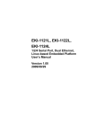
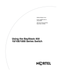
Figure 1-1 shows a differentiated services network that includes a server manager
and a policy server. If you manually configure filters, the policy server and server
manager would not be included.
Server manager
ISP or enterprise network
Policy server
Host
BLN
Highperformance
router
ASN
Host
DFS0001A
Figure 1-1.
308620-14.20 Rev 00
Differentiated Services Network
1-3
Configuring Differentiated Services
Communicating with the OPS Policy Server
If your differentiated services network uses an OPS policy server, the router uses
the COPS protocol to communicate with the policy server. The router is the COPS
client. The COPS client uses the Transmission Control Protocol (TCP) to
communicate with the policy server. The COPS client can connect to only one
server at a time, choosing the server from a list of servers that you define.
When the router requests a filter from the policy server, the server responds with
its own request to perform one or more of the following actions:
•
Install a new filter.
•
Update an existing filter.
•
Disable or enable an existing filter.
•
Delete an existing filter.
For each request, the COPS client on the router takes the necessary action and
then sends an acknowledgment back to the policy server. The policy server can
also send unsolicited requests.
If an interface on the router becomes inactive or terminates, the COPS client
deletes all filters from that interface. After the interface recovers, the router needs
to request the filters from the policy server again. If the connection to the policy
server is temporarily lost, the COPS client software attempts to reconnect to the
server. In this case, the router does not delete the filters.
The policy server assigns an ID to each filter before it installs the filter on the
router. The policy server can then change an installed filter based on that ID. If the
policy server requests an update or the removal of a nonexistent filter, the router
ignores the request and sends an error message to the policy server. You can view
the filters installed by the policy server using the router’s traffic filters feature, but
you cannot modify them.
For more information about configuring the OPS policy server, see Managing
Policy Information in Optivity Policy Services.
1-4
308620-14.20 Rev 00
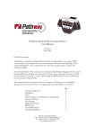
Differentiated Services Overview
Figure 1-2 shows the Nortel Networks OPS policy server architecture.
Application server
Web server
Server manager
LDAP
LDAP
Policy information
is placed in
LDAP server
the database
with policy
database
GUI
OPS policy server/
COPS server
PC
TCP connection
to the router
PC using
Windows NT
DFS0004A
Figure 1-2.
Architecture of the OPS Policy Server
Marking Packets for Specific Services
A packet’s assigned level of service determines whether the packet receives
preferential treatment as it travels through the network. The DS field has a specific
value that determines the service.
If the router communicates with a policy server, the process of installing filters
and marking packets is as follows:
1.
The edge router contacts the policy server with a configuration request. This
happens automatically as part of the router’s normal differentiated services
activity for each differentiated services interface.
2.
The policy server responds by downloading a set of flow filters from its
database to the edge router.
3.
When a packet arrives at a router’s differentiated services interface, the router
checks its flow filters, if any are installed, to see whether the packet matches
the filter’s criteria.
308620-14.20 Rev 00
1-5
Configuring Differentiated Services
4.
Packets that match the flow filter criteria are marked by the differentiated
services application with a DS-field pattern specified by the filter. The value
in the DS field determines whether the packet is sent to a high-priority data
queue for preferential treatment.
5.
After a packet is marked, it is sent to the core network device where,
depending on the marking, the packet receives preferential treatment as it is
routed through the network and on to the destination host.
Figure 1-3 shows the Nortel Networks differentiated services architecture and
how the router marks a packet.
1-6
308620-14.20 Rev 00
Differentiated Services Overview
OPS policy server
TCP
connection
COPS client
communicates with the
policy server
COPS
client
3/4
1
Inbound
data
Differentiated services
application
2
Classification,
policing, and
marking
mechanism
Flows with the
DS field marked go to
protocol prioritization
High
queue
Premium
marked
flows
Tiered
Protocol
marked
prioritization Medium
queue flows
by mark in
DS field
Unmarked
flows
Low
queue
(best effort)
Depending upon filter
action, DiffServ may mark
packets for protocol prioritization
1. Router receives data.
2. There is a filter match and the differentiated services application is notified.
3. Router examines filter action specified in policy obtained from policy server.
4. Differentiated services application applies actions to packets meeting the filter
criteria.
DFS0005A
Figure 1-3.
Nortel Networks Differentiated Services Architecture
308620-14.20 Rev 00
1-7
Configuring Differentiated Services
URL Filters
The router can filter and mark Hypertext Transfer Protocol (HTTP) traffic based
on uniform resource locator (URL) strings. For the router to use a URL filter, the
filter must be installed by the policy server or configured manually. The filter must
contain the URL string and optionally, any of the following information:
•
Source IP address
•
Destination IP address
•
Destination port (the default port is 80)
Only the URL string is required, but for efficient data transmission, it is useful to
also include one of the other filter criteria.
After the flow filters are configured on the router, the router can mark inbound
HTTP traffic for transmission through the network. If the router receives data that
matches a URL filter, the router installs another filter, called the dynamic filter, on
the next-hop interface, which is an interface on this same router.
The dynamic filter is available for the duration of the HTTP session. The dynamic
filter is deleted if there is no data activity during the time period specified by the
URL idle out timer. The original URL filter remains installed on the router.
For information about setting the URL idle out timer, see “Modifying a
Differentiated Services Interface” on page 4-2.
Note: Even if you configure URL filters manually (static configuration), the
differentiated services application uses COPS to install the dynamic filter.
URL filters are the only filters that create these dynamic filters.
You must configure differentiated services on all possible next-hop interfaces on
the router, or at least on all next-hop interfaces where the HTTP servers can
reside. Otherwise, the router will not be able to mark the return packets.
1-8
308620-14.20 Rev 00
Differentiated Services Overview
Queue Management and Scheduling (QMS)
BayRS includes queue management and scheduling (QMS) mechanisms to
support differentiated services. The weighted random early detection (WRED)
algorithm is used for queue management to drop packets selectively based on
packet preference. A queue scheduling algorithm called deficit round robin (DRR)
provides fair queuing.
Queue Management Using WRED
Random early detection (RED) is a popular algorithm for queue management.
RED is an active queue management algorithm that drops packets when
congestion is detected, before a queue becomes full. RED allows selective
dropping of packets.
RED works on a time-averaged queue length, not an instantaneous one, to prevent
problems with low-bandwidth, high-burst queues. Packets are dropped from
queues on a probability basis, which increases as the average queue size grows.
When a queue reaches the max-threshold value set for the associated RED
function (the default is 80%), probability reaches 100 percent.
The router computes average queue size and can detect oncoming congestion.
When the min-threshold value is reached, the router begins dropping packets in
direct relation to any increase in average queue size until the average queue size
falls below the min-threshold value. If the originating router is using TCP, it
detects packet loss, requests a re-send, and reduces the window size for
acknowledgment. In effect, it reduces the transmission rate in response to
congestion.
The BayRS implementation of DSQMS allows a mix of strict priority queuing and
bandwidth allocation on a single interface. Flows entering either a weighted or a
priority queue can then be managed by RED. Assigning different RED functions
to each traffic class (DSCP) is known as weighted RED or WRED.
The process of assigning different drop probabilities (WRED) on a per flow or
class (DSCP) basis allows a more granular approach to managing flows or traffic
types of different packet sizes. You can configure WRED on a queue-by-queue
basis.
308620-14.20 Rev 00
1-9
Configuring Differentiated Services
Queue Scheduling Using DRR
Differentiated services traffic filters sort incoming IP traffic and mark it with a
particular differentiated services code point (DSCP, formerly known as type of
service or ToS). Based on the DSCP, the router will queue traffic and then
schedule it for transmission. The DSCP marking allows DSQMS to separate
packets into classes and place them in queues that enable the router to handle each
class of traffic differently.
Queue scheduling manages the allocation of bandwidth among queues. Queue
scheduling affects the sequence in which the data leaves the WAN interface; it
does not affect traffic as it enters the router.
Like the queue management function, differentiated services queue scheduling
supports a mix of priority and bandwidth allocation (or weighted) queues. For
example, you could sort delay-sensitive traffic into two priority queues configured
for strict dequeuing and dedicate 10% of the link bandwidth to these two queues.
The remaining 90% of the link bandwidth could be shared among three weighted
fair queues, each configured with a percentage of bandwidth (or weight).
Priority queues are scheduled first, and the amount of traffic dequeued is
determined by a configurable timer, called a priority time quantum, so that
subsequent priority and weighted queues are serviced.
Weighted queues are serviced in round-robin fashion. In this scheme, a
high-bandwidth link with larger packets can consume more than its weighted
share compared to a low-bandwidth link with smaller packets. To prevent this
problem, link bandwidth, weight, and an average “one-round” service timer are
calculated together to create a queue quantum that determines scheduling.
The scheduler selects a queue to transmit from and its queue quantum is
determined. As packets leave the queue, its queue quantum balance is decreased
by the packets’ size. The scheduler moves to the next queue when the current
queue’s balance becomes negative, at which time the queue is considered in
deficit. This is the “deficit” element of deficit round robin. The scheduler counts
the deficit against the queue quantum balance on the next round-robin dequeuing
pass.
1-10
308620-14.20 Rev 00
Chapter 2
Starting Differentiated Services
The quickest way to configure differentiated services on the router is to enable it
with the default configuration that Nortel Networks software supplies. This
configuration uses all available default values for the interface and COPS
parameters. You need to supply values only for required parameters.
This chapter includes the following topics:
Topic
Page
Planning for a Differentiated Services Network
2-2
Starting Configuration Tools
2-2
Preparing a Configuration File
2-2
Starting Differentiated Services Using the BCC
2-3
Starting Differentiated Services Using Site Manager
2-5
Configuring Queue Management and Scheduling
2-7
Where to Go Next
2-13
308620-14.20 Rev 00
2-1
Configuring Differentiated Services
Planning for a Differentiated Services Network
This guide primarily explains how to configure a Nortel Networks router as a
differentiated services edge device.
For the router to successfully operate in a differentiated services network, you
must obtain the following information before you configure differentiated services
on the router:
•
The IP address of the policy server.
•
The COPS client IP address and ID of the router. Provide this information to
the administrator configuring the policy server.
Starting Configuration Tools
Before you configure differentiated services, refer to the following user guides for
instructions on how to start and use the Nortel Networks configuration tool of
your choice. (You must use the BCC to configure queue management and
scheduling.)
•
Using the Bay Command Console (BCC)
•
Configuring and Managing Routers with Site Manager
These guides also describe generally how to create and modify a device
configuration.
Preparing a Configuration File
Before starting differentiated services, you must create and save a configuration
file with at least one IP interface. The physical interface can be any LAN port, for
example, Ethernet or token ring.
For information about creating a configuration file, see Quick-Starting Routers.
You can start differentiated services using the BCC or Site Manager.
2-2
308620-14.20 Rev 00
Starting Differentiated Services
Starting Differentiated Services Using the BCC
Starting differentiated services involves enabling differentiated services on the
router, choosing a filter mechanism, and enabling the COPS protocol (if
applicable).
Enabling Differentiated Services
To enable differentiated services on the router using the BCC, you must first add
differentiated services globally to the router and then add it to each interface that
will support differentiated services.
Note: The BCC will not let you configure differentiated services on an
interface that has traffic filters. You must first delete the traffic filters before
you can add differentiated services to the interface.
To configure differentiated services globally on the router with the default
settings:
1.
In configuration mode, navigate to the global IP prompt (for example,
box; ip).
box# ip
ip#
2.
Configure differentiated services for IP.
ip# diffserv
diffserv#
To configure differentiated services on an IP interface:
1.
Navigate to the IP interface prompt (for example, box; ethernet/2/2;
ip/2.2.2.2/255.0.0.0).
2.
Enable differentiated services on the interface.
ip/2.2.2.2/255.0.0.0# diffserv
diffserv/2.2.2.2#
The BCC assigns default values to all differentiated services parameters.
308620-14.20 Rev 00
2-3
Configuring Differentiated Services
Choosing a Filter Mechanism
When you enable differentiated services, you must select a mechanism for
installing filters on the router. The router uses filters to determine which packets it
should mark for special treatment through the network. You can either enable the
COPS protocol or manually configure filters.
Go to one of the following sections to configure a filter mechanism:
•
“Enabling COPS” (next section)
•
“Creating Static Filters Using the BCC” on page 3-5
Enabling COPS
If the router will receive filters from a policy server, enable COPS so that the
router can communicate with the policy server.
To enable COPS:
1.
In configuration mode, navigate to the top-level box or stack prompt.
2.
Enable COPS, providing the router differentiated services IP address
that will be the COPS client address and an alphanumeric identification
for the router.
box# cops address 2.2.2.2 id athens
cops#
3.
Configure a COPS server, providing the IP address of a policy server.
cops# cops-server 192.1.1.1
cops-server/192.1.1.1# back
cops#
4.
Navigate to the IP interface on which you are configuring differentiated
services (for example, box; serial/5/1; ppp; ip/2.2.2.2/255.0.0.0).
5.
Enable COPS on the interface:
ip/2.2.2.2/255.0.0.0# diffserv config-type cops
diffserv/2.2.2.2#
2-4
308620-14.20 Rev 00
Starting Differentiated Services
Starting Differentiated Services Using Site Manager
Starting differentiated services involves enabling differentiated services on an IP
interface, choosing a filter mechanism, and enabling the COPS protocol (if
applicable).
Enabling Differentiated Services
In Site Manager, you need only configure differentiated services on a per-interface
basis.
Note: The router does not allow IP traffic filters on a differentiated services
interface. If you add differentiated services to an interface that already has IP
traffic filters configured, Site Manager will remove the traffic filters.
To enable differentiated services on an IP interface, complete the following tasks:
Site Manager Procedure
You do this
System responds
1. In the Configuration Manager window,
click on an IP interface connector.
The Add Circuit window opens.
2. Accept the default circuit name or enter a
new name, then click on OK.
The Select Protocols window opens.
3. Scroll through the list of protocols and
choose DiffServ, then click on OK.
The IP Configuration window opens.
4. Enter the interface’s IP address and mask.
5. Click on OK.
The DiffServ Interface List window opens.
6. If you want to enable COPS, go to
You return to the Configuration Manager
“Enabling COPS” on page 2-6. Otherwise, window.
click on Done.
Choosing a Filter Mechanism
When you enable differentiated services, you must select a mechanism for
installing filters on the router. The router uses filters to determine which packets it
should mark for special treatment through the network. You can either enable the
COPS protocol or manually configure filters.
308620-14.20 Rev 00
2-5
Configuring Differentiated Services
Go to one of the following sections to configure a filter mechanism:
•
“Enabling COPS” (next section)
•
“Creating Static Filters Using Site Manager” on page 3-17
Enabling COPS
To enable COPS, complete the following tasks:
Site Manager Procedure
You do this
System responds
1. In the DiffServ Interface List window, set
the Config Type parameter to COPS.
Click on Help or see the parameter
description on page A-4.
2. Click on Apply.
Site Manager displays a message
informing you that the static filters will be
deleted and asks if you want to continue.
3. Click on OK.
4. Click on COPS Global.
The Edit COPS Global Parameters
window opens.
5. Set the following parameters:
• Client IP Address
• Client ID
Click on Help or see the parameter
descriptions beginning on page A-8.
6. Click on OK.
You return to the DiffServ Interface List
window.
7. Click on COPS Servers.
The COPS Server List window opens.
8. Click on Add.
The COPS Server Record window opens.
9. Set the IP Address parameter. Click on
Help or see the parameter description on
page A-16.
2-6
10. Click on OK.
You return to the COPS Server List
window, with the server entry listed.
11. Click on Done.
You return to the DiffServ Interface List
window.
12. Click on Done.
You return to the Configuration Manager
window.
308620-14.20 Rev 00
Starting Differentiated Services
Configuring Queue Management and Scheduling
To configure queue management and scheduling for differentiated services, you
must use the BCC configuration tool. Figure 2-1 illustrates the BCC configuration
hierarchy for queue management and scheduling (DSQMS).
box
mce1
mct1
logical-line
hssi
dsqms-queue/1
dsqms
dsqms-queue/2
Differentiated services
code point (DSCP) value
serial
dsqms-queue/3
dsqms-classifier/00001100
dsqms-red/1
dsqms-classifier/00010100
dsqms-red/2
red
dsqms-classifier/00100100
dsqms-red/3
Figure 2-1.
BCC Configuration Hierarchy for QMS
How DSQMS Elements Work Together
Weighted RED (WRED) is the ability to assign different drop probabilities to
specified traffic flows within the same queue. To implement WRED, you must
first enable the RED algorithm on the router. (For more information about WRED,
see “Queue Management and Scheduling (QMS)” on page 1-9.)
After you enable RED, configure one or more instances of dsqms-red, each with
different settings. Each instance of dsqms-red defines a set of attributes for use of
the RED function. These instances of dsqms-red are used by one or more traffic
classifiers in one or more managed queues, as shown in Figure 2-2.
308620-14.20 Rev 00
2-7
Configuring Differentiated Services
The traffic classifiers within a DSQMS queue sort traffic based on the
differentiated services code point (DSCP) in the traffic headers. Traffic that
matches a traffic classifier is treated according to the attributes configured for the
queue and according to the referenced dsqms-red instance’s attributes, if
applicable. (Not all traffic classifiers reference a dsqms-red instance.) Figure 2-2
shows these relationships.
box
serial/2/1
dsqms/serial/2/1
dsqms-queue/1/serial/2/1
dsqms-classifier/00000100/serial/2/1
(red-id 1)
dsqms-classifier/00001000/serial/2/1
(red-id 3)
dsqms-classifier/00001100/serial/2/1
(red-id 1)
dsqms-red/1
red
dsqms-red/2
WRED implemented
dsqms-red/3
Figure 2-2.
2-8
Relationship Between QMS Objects (Weighted RED Implementation)
308620-14.20 Rev 00
Starting Differentiated Services
Implementation Notes
The following guidelines can help you successfully configure DSQMS on your
router:
•
You can configure DSQMS on these interfaces only: HSSI, MCT1, MCE1,
and synchronous.
•
If you enable flow fairness on a queue, you cannot configure that queue as a
best-effort queue. For information about enabling flow fairness on a queue or
designating the queue as best effort, see “Modifying a DSQMS Queue” on
page 6-5.
•
If you configure both weighted and priority queues on an interface, you may
experience latency problems with the highest priority queues. To avoid such
problems:
-- Set the DSQMS interface parameter dequeue-at-line-rate to enabled
(the default value is disabled). See “Configuring DSQMS to Dequeue
Packets at Line Rate” on page 6-3 for instructions.
-- Ensure that the amount of high-priority traffic is not excessive in the
highest priority queues.
•
If you implement RED for queue management instead of tail-drop (that is,
you set the queue parameter drop-type to red and you associate the queue
classifier with a RED function), the probability of dropping packets may
adversely affect the latency requirements of some applications. Adjust the
following parameters to achieve the required latency levels for the queue:
-- RED parameters min-threshold and max-threshold (see “Modifying
RED Parameters” on page 6-2 for instructions).
-- Queue parameters average-queue-gain and idle-queue-loss-rate (see
“Modifying a DSQMS Queue” on page 6-5 for instructions).
308620-14.20 Rev 00
2-9
Configuring Differentiated Services
DSQMS Configuration Steps
To configure DSQMS, you perform the following steps. Each step is described in
the following sections:
1.
Enable the weighted RED algorithm on the router.
2.
Create one or more sets of attributes (dsqms-red objects) that can be used by
queues on the interfaces.
3.
Enable DSQMS on an interface.
4.
Create one or more queues on the interface.
5.
Create one or more traffic classifiers on the queue.
To see an extended example of an initial DSQMS configuration, see “Queue
Management and Scheduling Configuration Example” on page B-11.
Enabling the RED Algorithm
You must enable the RED algorithm to configure instances of dsqms-red. To
enable RED, navigate to the top-level box or stack prompt and enter:
red
For example, the following command enables RED on a router:
box# red
red#
RED has no configurable parameters.
Configuring an Instance of dsqms-red
To add an instance of dsqms-red to the configuration, navigate to the RED prompt
(for example, box; red) and enter:
dsqms-red id <id_number> [min-threshold <min_value>]
[max-threshold <max_value>] [first-order-const <first_value>]
[second-order-const <second_value>]
id_number is a simple numerical identifier that identifies the instance (set of
attributes) for reference by traffic classifiers.
2-10
308620-14.20 Rev 00
Starting Differentiated Services
min_value is the queue size below which no packets are dropped by RED.
max_value is the queue size above which all packets are dropped by RED.
first_value is the first order constant used when calculating drop probability based
on the average queue fraction, the queue size, and the min-threshold value.
second_value is the second order constant used when calculating drop probability
based on the average queue fraction, the queue size, and the min-threshold value.
For example, the following command adds the first instance of dsqms-red:
red# dsqms-red id 1
dsqms-red/1#
This command sets up one dsqms-red instance with the default values for how
RED functions. You can change these values and create additional dsqms-red
instances with different values. For more information, see “Modifying RED
Parameters” on page 6-2.
Configuring DSQMS on an Interface
After you enable RED, perform the following steps to set up DSQMS on one or
more interfaces:
1.
Enable DSQMS on one or more interfaces.
2.
Configure a DSQMS queue on the interface.
3.
Configure a traffic classifier for the queue.
These steps are described in detail in the following sections.
Enabling DSQMS on an Interface
To enable DSQMS, navigate to the prompt for the interface where you want to use
DSQMS, and enter:
dsqms
For example, the following command enables DSQMS on serial interface 2/1:
serial/2/1# dsqms
dsqms/serial/2/1#
308620-14.20 Rev 00
2-11
Configuring Differentiated Services
Adding a DSQMS Queue to an Interface
To configure a DSQMS queue on an interface, navigate to the DSQMS prompt for
the interface (for example, box; serial/2/1; dsqms) and enter:
dsqms-queue id <id_number>
id_number is a simple numerical identifier for the queue.
For example, the following commands create the first DSQMS queue on serial
interface 2/1 and enable the queue (you must manually enable the queue):
dsqms/serial/2/1# dsqms-queue id 1
dsqms-queue/1/serial/2/1# state enabled
dsqms-queue/1/serial/2/1#
Note: Unlike most BCC objects, which are enabled by default when you
create them, a DSQMS queue is disabled by default (the state parameter is set
to disabled). You must explicitly enable the queue.
DSQMS queues have a number of parameters that you use to customize DSQMS
for your requirements. See “Modifying a DSQMS Queue” on page 6-5.
If you want to add traffic classifiers to the queue, go to the next section. If you
have finished configuring the queue, you must manually start DSQMS on the
interface by entering the restart command at the DSQMS interface prompt:
dsqms-queue/1/serial/2/1# back
dsqms/serial/2/1# restart set
dsqms/serial/2/1#
Adding a Traffic Classifier to a Queue
To configure a traffic classifier for a queue, navigate to the DSQMS queue prompt
(for example, box; serial/2/1; dsqms; dsqms-queue 1) and enter:
dsqms-classifier dscp <binary_octet> [red-id <dsqms_red_id_number>]
binary_octet is the 8-digit differentiated services code point value found in packet
headers to distinguish how differentiated services should classify incoming traffic.
dsqms_red_id_number is the numerical identifier of the dsqms-red instance that
this traffic classifier will use to manage traffic. This parameter is optional.
2-12
308620-14.20 Rev 00
Starting Differentiated Services
For example, the following command configures a traffic classifier on the first
queue on serial interface 2/1:
dsqms-queue/1/serial/2/1# dsqms-classifier dscp 00001100 red-id 1
dsqms-classifier/00001100/serial/2/1#
Typically, you create additional queues and additional traffic classifiers with
different RED functions within each queue. See Figure 2-2 on page 2-8.
If you want to add other traffic classifiers to the queue or other queues to the
interface, use the instructions in this section. If you have finished configuring the
queue, you must manually start DSQMS on the interface by entering the restart
command at the DSQMS interface prompt:
dsqms-classifier/00001100/serial/2/1# back
dsqms-queue/1/serial/2/1# back
dsqms/serial/2/1# restart set
dsqms/serial/2/1#
Where to Go Next
After you complete the steps in this chapter, differentiated services should be
operating on at least one interface.
•
If you chose to manually configure traffic filters, go to Chapter 3,
“Configuring Static Traffic Filters for Differentiated Services.”
•
To customize the differentiated services configuration, go to Chapter 4,
“Customizing Differentiated Services.”
•
To customize COPS services, go to Chapter 5, “Customizing COPS.”
•
To customize DSQMS, go to Chapter 6, “Customizing Queue Management
and Scheduling.”
308620-14.20 Rev 00
2-13
Chapter 3
Configuring Static Traffic Filters for Differentiated
Services
If you do not have a policy server or if you chose to use static traffic filters when
you started differentiated services, you must create traffic filters. This chapter
describes how to create differentiated services traffic filters and includes the
following topics:
Topic
Page
DiffServ Traffic Filter Concepts and Terminology
3-1
Creating Static Filters Using the BCC
3-5
Creating Static Filters Using Site Manager
3-17
Where to Go Next
3-22
DiffServ Traffic Filter Concepts and Terminology
This section provides background information for the sections on configuring
traffic filters that follow it.
308620-14.20 Rev 00
3-1
Configuring Differentiated Services
Traffic Filter Templates
A traffic filter template is a reusable, predefined specification for a traffic filter. It
consists of a complete filter specification, but is not associated with a specific
differentiated services interface. Each traffic filter template must have a unique
name, preferably one that identifies its function.
You can create and use differentiated services traffic filter templates only when
working in Site Manager. The BCC does not support differentiated services traffic
filter templates.
Traffic Filters
Differentiated services traffic filters mark packets in their DS field for special
treatment through the network. Using traffic filters, you can lower or raise the
packets’ priority or control drop probability for types of traffic using DSQMS and
RED.
Each traffic filter has the following properties:
•
A unique name, preferably one that identifies its function
•
An optional filter precedence value
You create differentiated services traffic filters on a differentiated services
interface. You can apply a traffic filter template to the filter if you are working in
Site Manager.
Traffic filter templates and traffic filters contain the following components:
•
Criteria
The portion of the incoming packet, frame, or datagram header to be
examined
•
Ranges
Numeric values (often addresses) to be compared with the contents of
examined packets
•
Actions
What happens to packets that match the criteria and ranges specified in the
traffic filter
3-2
308620-14.20 Rev 00
Configuring Static Traffic Filters for Differentiated Services
Filter Precedence
To specify a traffic filter’s relative priority among other traffic filters applied to the
differentiated services interface, you assign the traffic filter a precedence value. If
you do not explicitly assign a precedence when you create the traffic filter, the
software automatically assigns a precedence equal to the highest priority value
plus 1.
For example, if a differentiated services interface has only two traffic filters, one
with a precedence of 2 and the other with a precedence of 3, and you assign a new
filter without explicitly identifying a precedence, the software assigns a
precedence of 4 to the newly added filter. To avoid the need to explicitly assign
precedence numbers, assign the traffic filters to a differentiated services interface
in the same order that you want the software to compare them to each packet.
You can specify a precedence value from 1 through 127. The lower the precedence
value, the higher its priority. Thus, if a filter has a precedence of 1, the software
always processes that filter first for each incoming packet.
The software displays an error message if you attempt to assign a filter to an
interface that already has the maximum number of filters (127). If a differentiated
services interface has fewer that 127 filters, but has a filter with a precedence of
127, you cannot add another filter unless you explicitly assign a precedence less
than or equal to an available precedence.
308620-14.20 Rev 00
3-3
Configuring Differentiated Services
Filter Criteria
When you create a differentiated services traffic filter template or a differentiated
services traffic filter, you must supply filter criteria and actions.
You can filter traffic based on specified bit patterns in one of the following headers
in an IP datagram:
•
IP header (including the DSCP)
•
Header of the upper-layer protocol (TCP or UDP)
Another feature unique to differentiated services filters is that you can use URLs
as filter criteria, which enables the router to mark HTTP packets.
You define a criterion for creating differentiated services traffic filters based on bit
patterns in the packet header. You apply user-defined criteria by specifying
changes to the DSCP in the packet header.
Filter Actions
The filter action determines what happens to packets that match the filter criteria.
You can configure differentiated services traffic filters to perform the following
actions:
•
Log — For every packet that matches the filter entry, the router enters a
message in the event log. You can specify this action together with other
actions.
•
Accept — The router forwards a packet without marking it.
•
Drop — The router does not route any packet that matches the filter criteria.
•
Mark (the Site Manager DiffServ Set Field command) — The router sets the
DS byte in the IP header for all packets that match the filter criteria.
•
Police (the Site Manager DiffServ Set Police command) — The router
monitors the packet flow and determines whether that packet is in or out of the
profile. If the packet fits the profile, the router sets the DS byte.
For every packet that matches the filter criteria, the router sends an entry to the
system event log if you configure the log action.
3-4
308620-14.20 Rev 00
Configuring Static Traffic Filters for Differentiated Services
Creating Static Filters Using the BCC
To create a differentiated services traffic filter on a differentiated services
interface, enter the following command:
traffic-filter filter-name <name> [precedence <number>]
name is the name of the new differentiated services traffic filter.
number is any integer from 1 through 127. The software uses the precedence value
to determine the relative position of the filter in the sequence of filters to be
applied to each packet. The traffic filter with a precedence of 1 is always applied
first, and the traffic filter with a precedence of 127 is always applied last. If you do
not specify a precedence, the software automatically assigns a precedence equal to
the greatest precedence value on that interface plus 1.
Caution: Applying traffic filters to a differentiated services interface without
regard to their relative precedence can produce unwanted results. For more
information, see “Filter Precedence” on page 3-3.
Example - Creating a Traffic Filter
This example creates a traffic filter named “nortel” with no predefined precedence
value. The BCC calculates the next highest precedence value. Later this filter will
be set to match HTTP traffic from Nortel Networks. To create a differentiated
services traffic filter:
1.
Navigate to the differentiated services interface prompt (for example,
box; ethernet/2/1; ip/2.2.2.2/255.0.0.0; diffserv).
2.
Configure a differentiated services filter. You must supply a filter name.
diffserv/2.2.2.2# traffic-filter filter-name nortel
ds-filter/nortel/2.2.2.2#
You must set both filter criteria and filter actions to complete the creation of a
static filter. For more information, refer to the sections that follow and use the info
and ? (question mark) commands at the differentiated services traffic filter
prompt.
308620-14.20 Rev 00
3-5
Configuring Differentiated Services
Specifying Match Criteria
The match criteria in a filter specify which fields in the IP header of each packet
must contain the values that you specify. You can also specify certain fields in the
headers of TCP and UDP packets contained in the IP data field of IP packets.
To prepare to specify the filtering criteria, navigate to the traffic filter prompt (for
example, box; ethernet/2/1; ip/2.2.2.2/255.0.0.0; diffserv; traffic-filter nortel)
and enter:
match
You can specify match criteria for filters as described in the following sections:
Topic
Page
Source and destination network
3-6
Source and destination TCP and UDP port
3-7
Protocol identifier
3-9
DS field
3-10
URLs
3-11
TCP packets with ACK and RESET bits in the header
3-11
User-defined criteria
3-12
Specifying Source and Destination Networks As Match Criteria
To filter on source and destination networks, go to the match prompt (for example,
box; ethernet/2/1; ip/2.2.2.2/255.0.0.0; diffserv; traffic-filter nortel; match)
and do the following for each source and destination network that you want to
filter on:
1.
Enter the following command:
{source | destination}-network <address_range>
address_range specifies a range of IP addresses for source and destination
networks.
The source network or destination network prompt appears.
2.
Go back to the match prompt:
back
3-6
308620-14.20 Rev 00
Configuring Static Traffic Filters for Differentiated Services
Example - Source and Destination Network Criteria
match/ds-filter/nortel/2.2.2.2# source-network 2.2.2.2-4.4.4.4
source-network/ds-filter/nortel/2.2.2.2-4.4.4.4# back
match/ds-filter/nortel/2.2.2.2# destination-network 4.4.4.4-5.5.5.5
destination-network/ds-filter/nortel/4.4.4.4-5.5.5.5# back
match/ds-filter/nortel/2.2.2.2#
Specifying Source and Destination TCP and UDP Ports As Match
Criteria
To filter on TCP ports, UDP ports, or both, you can specify only one of the
following criteria for each filter:
•
Source TCP ports, destination TCP ports, or both
•
Source UDP ports, destination UDP ports, or both
•
Both destination TCP and UDP ports
•
Both source TCP and UDP ports
After you specify one of these options, the BCC prevents you from specifying
another in the same filter. For example, if you specify source TCP ports, you can
also specify destination TCP ports, but you cannot specify source UDP ports.
When you specify one of these values, the BCC automatically assigns the
associated protocol ID (6 for TCP or 17 for UDP) to the protocol parameter.
Therefore, you cannot modify the protocol parameter of a filter that specifies a
TCP or UDP port value.
To filter on TCP or UDP ports, navigate to the match prompt (for example, box;
ethernet/2/1; ip/2.2.2.2/255.0.0.0; diffserv; traffic-filter nortel; match) and
enter the following command:
<parameter> {<range_of_ports>}
parameter is one of the following (Table 3-1):
308620-14.20 Rev 00
3-7
Configuring Differentiated Services
Table 3-1.
TCP and UDP Match Criteria Parameters
Parameter
Specifies
src-tcp-ports
Source TCP port through which traffic is entering the network
dest-tcp-ports
Destination TCP port through which you are directing outbound
network traffic
src-udp-ports
Source UDP port through which traffic is entering the network
dest-udp-ports
Destination UDP port through which you are directing outbound
network traffic
dest-tcp-udp-ports Both destination TCP and UDP ports through which you are directing
outbound network traffic
src-tcp-udp-ports
Both source TCP and UDP ports through which traffic is entering the
network
range_of_ports is a space-delimited list.
Table 3-2 lists some common TCP port and UDP port values.
Table 3-2.
3-8
Common TCP Ports and Common UDP Ports
Description
TCP Port
Description
UDP Port
FTP
20, 21
DNS
53
Telnet
23
TFTP
69
SMTP
25
SNMP
161
DNS
53
SNMPTRAP
162
Gopher
70
HTTP
80-84
DLSw read port
2065
DLSw write port
2067
308620-14.20 Rev 00
Configuring Static Traffic Filters for Differentiated Services
Example - Source TCP Port
This example specifies source TCP ports 20, 80, and 53 through 56 as match
criteria for the filter “nortel”:
match/ds-filter/nortel/2.2.2.2# src-tcp-ports {20 80 53-56}
match/ds-filter/nortel/2.2.2.2#
Example - Destination TCP Port
This example specifies destination TCP ports 30, 90, and 50 through 53 as match
criteria:
match/ds-filter/nortel/2.2.2.2# dest-tcp-ports {30 90 50-53}
match/ds-filter/nortel/2.2.2.2#
Example - Source UDP Port
This example specifies source UDP port 162 as a match criterion:
match/ds-filter/nortel/2.2.2.2# src-udp-ports 162
match/ds-filter/nortel/2.2.2.2#
Example - Destination TCP and UDP Ports
This example specifies both destination TCP and UDP ports 53 as match criteria:
match/ds-filter/nortel/2.2.2.2# dest-tcp-udp-ports 53
match/ds-filter/nortel/2.2.2.2#
Specifying Protocol Identifiers As Match Criteria
Internet Protocol Version 4 (IPv4) specifies an 8-bit protocol field to identify the
next-level protocol. You can use the protocol field to identify traffic that you want
to filter on.
Note: If you filter on a TCP or UDP source or destination, the software
automatically changes the value to the protocol number associated with TCP
or UDP.
If you specify a protocol other than TCP or UDP, the software prevents you from
filtering on the TCP or UDP source or destination. Otherwise, the offset
associated with one of the parameters in the non-UDP/TCP packet could
coincidentally match the filter, and the software would perform the filter’s action.
308620-14.20 Rev 00
3-9
Configuring Differentiated Services
To filter traffic using the protocol field, go to the match prompt (for example, box;
ethernet/2/1; ip/2.2.2.2/255.0.0.0; diffserv; traffic-filter nortel; match) and
enter the following command:
protocol {<list_of_protocols>}
list_of_protocols can include any number of protocol identifiers. It can also
specify ranges of protocol identifiers.
Table 3-3 lists some common protocol ID codes for IP traffic.
Table 3-3.
Common Protocol IDs for IP Traffic
Protocol
ID Code (Decimal)
ICMP (Internet Control Message Protocol)
1
IGMP (Internet Group Management Protocol)
2
TCP (Transmission Control Protocol)
6
EGP (Exterior Gateway Protocol)
8
IGP (Interior Gateway Protocol)
9
UDP (User Datagram Protocol)
17
RSVP (Resource Reservation Protocol)
46
GRE (Generic Routing Encapsulation)
47
NHRP (Next Hop Resolution Protocol)
54
OSPF (Open Shortest Path First)
89
Example - Protocol Identifier Criteria
To match IGP and OSPF packets, enter the following command:
match/ds-filter/nortel/2.2.2.2# protocol {9 89}
match/ds-filter/nortel/2.2.2.2#
Specifying the DS Field As a Match Criterion
Differentiated services establishes an 8-bit field in the IP traffic header referred to
as the differentiated services code point (DSCP), or DS field. The DS field may be
altered by the filter actions of other differentiated services nodes in the network.
You can filter on the DS field to take advantage of prior DS field marking in your
network.
3-10
308620-14.20 Rev 00
Configuring Static Traffic Filters for Differentiated Services
To filter on the DS field, go to the match prompt (for example, box; ethernet/2/1;
ip/2.2.2.2/255.0.0.0; diffserv; traffic-filter nortel; match) and enter the
following command:
ds-field <octet>
octet specifies a binary DSCP from 00000000 through 11111100. Differentiated
services does not use the last two bits of the octet.
Example - DS Field Criterion
To match packets with a DSCP value of 11100000, enter the following command:
match/ds-filter/nortel/2.2.2.2# ds-field 11100000
match/ds-filter/nortel/2.2.2.2#
Specifying URLs As Match Criteria
To filter on URLs, go to the match prompt (for example, box; ethernet/2/1;
ip/2.2.2.2/255.0.0.0; diffserv; traffic-filter nortel; match) and enter the
following command:
urls {<first_url> <second_url> ... <last_url>}
first_url and the arguments that follow specify one or more URLs to filter. When
specifying multiple URLs, separate each one with a space.
Example - URL Criteria
match/ds-filter/nortel/2.2.2.2# urls {www.nortelnetworks.com www.nortel.com}
match/ds-filter/nortel/2.2.2.2#
Specifying TCP-Established Match Criteria
By default, the router does not filter packets on the ACK and RESET bits in the
TCP header. To allow the router to filter packets with the ACK and RESET bits,
go to the match prompt (for example, box; ethernet/2/1; ip/2.2.2.2/255.0.0.0;
diffserv; traffic-filter nortel; match) and enter the following command:
tcp-established {on | off}
308620-14.20 Rev 00
3-11
Configuring Differentiated Services
Example - TCP-Established Criteria
In this example, the router filters packets with the ACK and RESET bits in the
TCP header turned on.
match/ds-filter/nortel/2.2.2.2# tcp-established on
match/ds-filter/nortel/2.2.2.2#
Specifying User-Defined Match Criteria
You can specify user-defined criteria in differentiated services traffic filters by
specifying an offset and length based on the reference fields in the IP header.
To specify user-defined criteria, go to the match prompt (for example, box;
ethernet/2/1; ip/2.2.2.2/255.0.0.0; diffserv; traffic-filter nortel; match) and
enter:
user-defined reference <value> offset <value> bitwidth <value> range <value>
reference is a known bit position in the packet header, either start-ip-header or
end-ip-header.
offset specifies the first position of the filtered bit pattern in relation to the
reference point (measured in bits).
bitwidth specifies the total bit length that matches the packet criteria.
range specifies a minimum and maximum target value to apply to the match
criterion. For a single value, you must specify the minimum value in hexadecimal
format. You can precede the value with 0x.
Example - User-Defined Criteria
This example specifies user-defined criteria to create an IP traffic filter that drops
every packet that has a value of 192 at offset 96 from the beginning of the IP
header.
match/ds-filter/nortel/2.2.2.2# user-defined reference start-ip-header offset 96
bitwidth 16 range 0192
user-defined/filter/nortel/2.2.2.2/start-ip-header/96/16/0192# back
match/ds-filter/nortel/2.2.2.2# back
ds-filter/nortel/2.2.2.2# actions
actions/ds-filter/nortel/2.2.2.2# action drop
actions/ds-filter/nortel/2.2.2.2#
3-12
308620-14.20 Rev 00
Configuring Static Traffic Filters for Differentiated Services
Specifying the Action of Traffic Filters
By default, the action of each differentiated services traffic filter is to accept the
packet if it matches all the filter’s match criteria. You can use the mark and police
actions to change per-hop behavior of filtered traffic and to classify traffic for
RED protocol prioritization in DSQMS.
To change the filtering actions, navigate to the actions prompt (for example, box;
ethernet/2/1; ip/2.2.2.2/255.0.0.0; diffserv; traffic-filter nortel; actions) and
specify one or more of the actions described in Table 3-4.
Table 3-4.
Actions for DiffServ Traffic Filters
Action
Command Syntax Description
accept
action accept
The router processes any packet that matches the
filter criteria and ranges. This value is the default
action.
drop
action drop
The router does not route any packet that matches
the filter criteria and ranges.
mark
action mark
<dscp_octet>
The router changes the DSCP (DS field) of any
packet that matches the filter to the specified binary
octet.
police
action police;
police
Police actions are activated on the router and you
enter the police context. You must specify policing
parameters as described in Table 3-5.
Example - Mark Action
This example creates a filter that marks packets sent from IP address 192.168.44.5
with a new value in the DS field.
ds-filter/nortel/2.2.2.2# match
match/ds-filter/nortel/2.2.2.2# source-network 192.168.44.5
source-network/ds-filter/nortel/192.168.44.5# back
match/ds-filter/nortel/2.2.2.2# back
ds-filter/nortel/2.2.2.2# actions
actions/ds-filter/nortel/2.2.2.2# action mark mark-value 00111100
actions/ds-filter/nortel/2.2.2.2#
The mark value is a binary number. Because the last two bits of the DS field are
currently unused, the last two bits for mark-value must be set to 0.
308620-14.20 Rev 00
3-13
Configuring Differentiated Services
For information about how DSQMS uses the DS field, refer to “Configuring
Queue Management and Scheduling” on page 2-7 and to RFC 2474, “Definition
of the Differentiated Services Field (DS Field) in the IPv4 and IPv6 Headers.”
Specifying Police Parameters
If you add the police action to a filter, you must configure policing parameters in
the police context. To set the policing actions, navigate to the police prompt (for
example, box; ethernet/2/1; ip/2.2.2.2/255.0.0.0; diffserv; traffic-filter nortel;
actions; police) and specify one or more of the parameters described in
Table 3-5.
Table 3-5.
Parameter
DS Police Parameters
Values
Function
inprofile-behavior mark (default)
no-change
Tells the router how to treat packets that are within
the filter profile
inprofile-marking 00000000
(default) through
11111100
Specifies the value that the DS byte is set to if the
policing algorithm accepts the packet. The value
represents the type of service that the packet
receives.
max-policed
0 through
4294967295
(default)
Specifies the maximum packet size that the router
allows for the network. This parameter lets the
router prevent large packets from being admitted
into the network.
min-policed
0 through
4294967295
(default 20)
Specifies the minimum packet size that the router
allows for the network. If the packet size is smaller
than the value set for this parameter, the router
uses this parameter value as the packet size.
outprofilebehavior
no-change
(default)
mark
drop
Tells the router how to treat the packet if it does not
fit the filter profile
outprofilemarking
00000000
(default) through
11111100
Tells the router how to mark the packet if the packet
size does not fit the filter profile, for example, if the
host is sending more data than it should
(continued)
3-14
308620-14.20 Rev 00
Configuring Static Traffic Filters for Differentiated Services
Table 3-5.
Parameter
DS Police Parameters (continued)
Values
Function
token-bucket-rate 0 (default)
through
4294967295
Sets the rate at which the router accepts data.
Specifying the data rate can prevent the host from
sending too much data to the router.
token-bucketsize
Determines the burst size of the data that the router
accepts. This parameter enables the router to
guard against large bursts of data; it balances the
flow of data.
0 (default)
through
4294967295
Example - Police Action
This example increases the min-policed value to 40 and decreases the max-policed
maximum packet size to 3000100100:
ds-filter/nortel/2.2.2.2# actions
actions/ds-filter/nortel/2.2.2.2# action police
actions/ds-filter/nortel/2.2.2.2# police
police/ds-filter/nortel/2.2.2.2# min-policed 40
police/ds-filter/nortel/2.2.2.2# max-policed 3000100100
police/ds-filter/nortel/2.2.2.2#
Specifying the Log Action
You can specify the log action in combination with other actions. By default, the
system event log file is set to off. To log traffic filter events and to specify the level
of detail that you want to include in the system event log, go to the actions prompt
(for example, box; ethernet/2/1; ip/2.2.2.2/255.0.0.0; diffserv; traffic-filter
nortel; actions) and enter:
action-log {off | on | detailed}
off (the default) specifies that no differentiated services traffic filter information is
written to the system event log file.
on indicates that when an incoming packet matches the criteria, the traffic filter
adds an entry that contains limited traffic filter information to the system event log
file.
detailed indicates that the traffic filter adds an entry that contains detailed
differentiated services traffic filter information to the system event log file.
308620-14.20 Rev 00
3-15
Configuring Differentiated Services
Disabling and Reenabling Traffic Filters
By default, traffic filters are enabled on a differentiated services interface. To
disable or reenable a traffic filter on a differentiated services interface, go to the
traffic filter prompt (for example, box; ethernet/2/1; ip/2.2.2.2/255.0.0.0;
diffserv; traffic-filter nortel) and enter:
state {disabled | enabled}
The following example shows how to disable and reenable a differentiated
services traffic filter on an interface:
ds-filter/nortel/2.2.2.2# state disabled
ds-filter/nortel/2.2.2.2# state enabled
ds-filter/nortel/2.2.2.2#
Configuration Example
This example demonstrates the entire process of creating a differentiated services
traffic filter on a differentiated services interface. The traffic filter drops HTTP
traffic.
box# ethernet/2/1; ip/2.2.2.2/255.0.0.0; diffserv
diffserv/2.2.2.2# traffic-filter filter-name filter2
ds-filter/filter2/2.2.2.2# match
match/ds-filter/filter2/2.2.2.2# dest-tcp-ports 80
match/ds-filter/filter2/2.2.2.2# back
ds-filter/filter2/2.2.2.2# actions
actions/ds-filter/filter2/2.2.2.2# action drop
actions/ds-filter/filter2/2.2.2.2# back
ds-filter/filter2/2.2.2.2# info
filter-name
filter2
precedence
1
state
enabled
ds-filter/filter2/2.2.2.2# back
diffserv/2.2.2.2#
3-16
308620-14.20 Rev 00
Configuring Static Traffic Filters for Differentiated Services
Creating Static Filters Using Site Manager
When you create traffic filters using Site Manager, understand the difference
between a traffic filter template and an actual traffic filter. A filter template is a
reusable, predefined specification for a traffic filter. You create an actual traffic
filter when you apply a filter template to a configured router interface. You can
apply a single template to as many interfaces as you want.
Each template must contain filter criteria and filter actions (log, drop, accept, set
DS field, set DS police). The actions are performed on the filtered packets.
Note: Log is the only action that you can combine with other actions. For
example, you cannot combine Set DS Field and Set DS Police for one filter.
Creating a Filter Template
To configure a differentiated services filter template, complete the following tasks:
Site Manager Procedure
You do this
System responds
1. In the Configuration Manager window,
choose Protocols.
The Protocols menu opens.
2. Choose IP.
The IP menu opens.
3. Choose DiffServ.
The DiffServ menu opens.
4. Choose Interfaces.
The DiffServ Interface List window opens.
5. Select the interface that you want to
modify and click on Traffic Filt.
The DiffServ Static Filters window opens.
6. Click on Template.
The Filter Template Management window
opens.
7. Click on Create.
The Create DiffServ Template window
opens.
8. Type a name for the template in the Filter
Name field.
9. Choose Criteria.
The Criteria menu opens.
10. Choose Add.
The Add menu opens.
(continued)
308620-14.20 Rev 00
3-17
Configuring Differentiated Services
Site Manager Procedure (continued)
You do this
System responds
11. Add one or more filter criteria.
12. Choose Action.
The Action menu opens.
13. Choose Add.
The Add menu opens.
14. To select the DS field for the filter action,
choose DiffServ Set Field and set a value
for the DS field: 00000000 through
11111111. See “DS Field” on page A-18
for more information.
15. To select the DiffServ Police for the filter
action, choose DiffServ Set Police and
set the following parameters:
• Token Bucket Rate (Kbps)
• Token Bucket Size (Bits)
• Inprofile Marking
• Out of Profile Marking
Click on Help or see the parameter
descriptions beginning on page A-20.
Accept the default values for the other
parameters.
16. Click on Save.
You return to the Create DiffServ
Template window.
17. Click on OK.
You return to the Filter Template
Management window.
18. Click on Done.
You return to the DiffServ Static Filters
window.
19. Apply the filter template according to the
instructions in the next section.
3-18
308620-14.20 Rev 00
Configuring Static Traffic Filters for Differentiated Services
Applying the Template to a Filter
After you create your differentiated services filter template, you create a filter by
applying the template to a differentiated services interface.
To apply a filter template, complete the following tasks:
Site Manager Procedure
You do this
System responds
1. In the DiffServ Static Filters window, click
on Create.
The Create Filter window opens.
2. Type a name for the filter in the Filter
Name field.
3. Select the differentiated services interface
that will use this filter in the Interfaces list.
4. Select a template in the Templates list.
5. Click on OK.
You return to the DiffServ Static Filters
window. Site Manager displays the filter
name and its interface in the list.
6. Click on Done until you return to the
Configuration Manager window.
308620-14.20 Rev 00
3-19
Configuring Differentiated Services
Configuring Filters for HTTP Packets
To modify a filter to include URLs, complete the following tasks:
Site Manager Procedure
You do this
System responds
1. See “Creating a Filter Template” on
page 3-17 and follow steps 1 through 5 in
the table.
2. Click on Edit.
The Edit DiffServ Filters window opens.
3. Choose Criteria.
The Criteria menu opens.
4. Choose Add.
The Add menu opens.
5. Choose Add URL.
The Add URL window opens.
6. Set the URL parameter. See the
parameter description on page A-23.
7. Click on OK.
You return to the Edit DiffServ Filters
window.
8. Click on OK.
You return to the DiffServ Static Filters
window.
9. Click on Done until you return to the
Configuration Manager window.
You must always associate filter criteria with a filter action. In this way, the router
uses the URL criterion with the appropriate differentiated services action, for
example, DiffServ Set Field, to determine how to mark packets.
3-20
308620-14.20 Rev 00
Configuring Static Traffic Filters for Differentiated Services
Customizing the Action of Traffic Filters
These procedures assume that you created a filter template and applied it to a
filter. To modify a filter that includes the DS Field or DS Police action, complete
the following tasks:
Site Manager Procedure
You do this
System responds
1. In the Configuration Manager window,
choose Protocols.
The Protocols menu opens.
2. Choose IP.
The IP menu opens.
3. Choose DiffServ.
The DiffServ menu opens.
4. Choose Interfaces.
The DiffServ Interface List window opens.
5. Select the interface that you want to
modify and click on Traffic Filt.
The DiffServ Static Filters window opens.
6. Select the filter that you want to edit and
click on Edit.
The Edit DiffServ Filters window opens.
7. To change the DS field entry, choose
Action > Edit DS Field.
The DS Field window opens.
8. To modify the DS Police action, choose
Action > Edit DS Police and set the
following parameters:
• Token Bucket Rate (Kbps)
• Token Bucket Size (Bits)
• Min Policed (Bytes)
• Max Policed (Bytes)
• Inprofile Marking
• Inprofile Behavior
• Out of Profile Marking
• Out of Profile Behavior
Click on Help or see the parameter
descriptions beginning on page A-20.
9. Click on Save.
You return to the Edit DiffServ Filters
window.
10. Click on OK.
You return to the DiffServ Static Filters
window.
11. Click on Done until you return to the
Configuration Manager window.
308620-14.20 Rev 00
3-21
Configuring Differentiated Services
Modifying URL Match Criteria
These procedures assume that you created a filter template and applied it to a
filter. To modify a filter that includes a URL as a criterion, complete the following
tasks:
Site Manager Procedure
You do this
System responds
1. In the Configuration Manager window,
choose Protocols.
The Protocols menu opens.
2. Choose IP.
The IP menu opens.
3. Choose DiffServ.
The DiffServ menu opens.
4. Choose Interfaces.
The DiffServ Interface List window opens.
5. Select the interface that you want to
modify and click on Traffic Filt.
The DiffServ Static Filters window opens.
6. Select the filter that you want to edit and
click on Edit.
The Edit DiffServ Filters window opens.
7. Select a URL and click on Modify.
The Edit URL window opens.
8. Make any modifications, then click on OK. You return to the Edit DiffServ Filters
window.
9. Click on OK.
You return to the DiffServ Static Filters
window.
10. Click on Done until you return to the
Configuration Manager window.
Where to Go Next
After you complete the steps in this chapter, differentiated services traffic filters
should be operating on at least one interface.
3-22
•
To customize the differentiated services configuration, go to Chapter 4,
“Customizing Differentiated Services.”
•
To customize DSQMS, go to Chapter 6, “Customizing Queue Management
and Scheduling.”
308620-14.20 Rev 00
Chapter 4
Customizing Differentiated Services
When you enable differentiated services, default values are in effect for all
parameters. Depending on your network requirements, you may want to change
these values.
This chapter describes how to customize your differentiated services
configuration and includes the following topics:
Topic
Page
Modifying a Differentiated Services Interface
4-2
Disabling and Reenabling Differentiated Services
4-4
Deleting a Differentiated Services Interface
4-6
Additional customization information is available:
•
For information about customizing static traffic filters, refer to Chapter 3,
“Configuring Static Traffic Filters for Differentiated Services.”
•
For information about customizing COPS, refer to Chapter 5, “Customizing
COPS.”
•
For information about customizing queue management, refer to Chapter 6,
“Customizing Queue Management and Scheduling.”
308620-14.20 Rev 00
4-1
Configuring Differentiated Services
Modifying a Differentiated Services Interface
You can modify the configuration type (static or COPS) of a differentiated
services interface, specify which debug messages for an interface are stored in the
router’s event log, and specify an idle timer for URL filters.
For instructions on adding differentiated services to an IP interface, see “Starting
Differentiated Services Using the BCC” on page 2-3 or “Starting Differentiated
Services Using Site Manager” on page 2-5.
Note: If you want to change the configuration type from static to COPS, see
“Enabling COPS” on page 2-4. If you want to change the configuration type
from COPS to static, read the instructions in this section and then go to
Chapter 3, “Configuring Static Traffic Filters for Differentiated Services.”
Using the BCC
To modify a differentiated services interface:
1.
Navigate to the diffserv context on the IP interface (for example, box;
serial/3/1; ip/2.2.2.2/255.0.0.0; diffserv).
ip/2.2.2.2/255.0.0.0# diffserv
diffserv/2.2.2.2#
2.
Enter one or more of the following commands:
config-type {static | cops}
debug-level {extra-debug | filter-maintenance | interaction-with-cops |
ip-interaction | trigger-event}
url-idleout-timer <integer>
integer is the amount of time (in seconds) that the router waits before a
dynamic URL filter on the next-hop interface is deleted.
Refer to the parameter description for “Debug Log Mask (hex)” on page A-3
for a description of the debug-level parameters.
For example, the following commands configure the router to send trigger
messages to the event log and set the URL timeout to 240 seconds:
diffserv/2.2.2.2# debug-level trigger-events
diffserv/2.2.2.2# url-idleout-timer 240
diffserv/2.2.2.2#
4-2
308620-14.20 Rev 00
Customizing Differentiated Services
Using Site Manager
To modify a differentiated services interface, complete the following tasks:
Site Manager Procedure
You do this
System responds
1. In the Configuration Manager window,
choose Protocols.
The Protocols menu opens.
2. Choose IP.
The IP menu opens.
3. Choose DiffServ.
The DiffServ menu opens.
4. Choose Interfaces.
The DiffServ Interface List window opens.
5. Select the interface that you want to
modify.
6. Set the following parameters:
• Config Type
• Debug Log Mask (hex)
• URL Idle Out Timer
Click on Help or see the parameter
descriptions beginning on page A-3.
7. Click on Done.
308620-14.20 Rev 00
You return to the Configuration Manager
window.
4-3
Configuring Differentiated Services
Disabling and Reenabling Differentiated Services
After you create a differentiated services interface, by default it is enabled. You
can disable and reenable a single interface or all interfaces at any time.
Using the BCC
To disable a single interface:
1.
Navigate to the diffserv prompt on the IP interface.
ip/2.2.2.2/255.0.0.0# diffserv
diffserv/2.2.2.2#
2.
Enter the following command:
diffserv/2.2.2.2# disable
diffserv/2.2.2.2#
To reenable differentiated services on an interface, enter the following command:
diffserv/2.2.2.2# enable
diffserv/2.2.2.2#
To globally disable differentiated services:
1.
Navigate to the global IP prompt (for example, box; ip).
2.
Enter the following command:
ip# disable diffserv
ip#
To globally reenable differentiated services, enter the following command:
ip# enable diffserv
ip#
4-4
308620-14.20 Rev 00
Customizing Differentiated Services
Using Site Manager
To disable or reenable a single interface, complete the following tasks:
Site Manager Procedure
You do this
System responds
1. In the Configuration Manager window,
choose Protocols.
The Protocols menu opens.
2. Choose IP.
The IP menu opens.
3. Choose DiffServ.
The DiffServ menu opens.
4. Choose Interfaces.
The DiffServ Interface List window opens.
5. Select the interface that you want to
disable or reenable.
6. Set the Enable parameter. Click on Help
or see the parameter description on
page A-3.
7. Click on Done.
You return to the Configuration Manager
window.
To globally disable or reenable all differentiated services interfaces, complete the
following tasks:
Site Manager Procedure
You do this
System responds
1. In the Configuration Manager window,
choose Protocols.
The Protocols menu opens.
2. Choose IP.
The IP menu opens.
3. Choose DiffServ.
The DiffServ menu opens.
4. Choose Global.
The Edit DiffServ Global Parameters
window opens.
5. Set the Enable parameter. Click on Help
or see the parameter description on
page A-6.
6. Click on Done.
308620-14.20 Rev 00
You return to the Configuration Manager
window.
4-5
Configuring Differentiated Services
Deleting a Differentiated Services Interface
You can delete differentiated services from a single interface or from all interfaces
on the router.
Using the BCC
To delete differentiated services from a single interface:
1.
Navigate to the IP interface prompt (for example, box; ethernet/2/1;
ip/2.2.2.2/255.0.0.0).
2.
Check whether any filter on the interface has a “police” filter action by
entering the following command:
ip/2.2.2.2/255.0.0.0# show diffserv traffic-filter detail
Filter: pur
Match:
tcp-udp destination-ports:
80-80
Action:
action mark mark-value: 00111100
ip/2.2.2.2/255.0.0.0#
For security reasons, you cannot delete differentiated services from an
interface with a policing filter without removing the filter first. If you are
certain that you no longer need to police the interface, delete the filter.
3.
Enter the following command:
ip/2.2.2.2/255.0.0.0# delete diffserv/2.2.2.2
ip/2.2.2.2/255.0.0.0#
To globally delete differentiated services:
1.
Delete differentiated services from each IP interface where it is
configured.
You cannot globally delete differentiated services using the BCC if any
differentiated services interfaces exist.
2.
Navigate to the global IP prompt (for example, box; ip).
3.
Enter the following command:
ip# delete diffserv
ip#
4-6
308620-14.20 Rev 00
Customizing Differentiated Services
Using Site Manager
To delete a single interface, complete the following tasks:
Site Manager Procedure
You do this
System responds
1. In the Configuration Manager window,
choose Protocols.
The Protocols menu opens.
2. Choose IP.
The IP menu opens.
3. Choose DiffServ.
The DiffServ menu opens.
4. Choose Interfaces.
The DiffServ Interface List window opens.
5. Select the interface that you want to
delete, and click on Delete.
Site Manager removes the interface from
the list.
6. Click on Done.
You return to the Configuration Manager
window.
To globally delete differentiated services from all IP interfaces on which it is
configured, complete the following tasks:
Site Manager Procedure
You do this
System responds
1. In the Configuration Manager window,
choose Protocols.
The Protocols menu opens.
2. Choose IP.
The IP menu opens.
3. Choose DiffServ.
The DiffServ menu opens.
4. Choose Delete.
A confirmation window prompts: Do you
REALLY want to delete
DiffServ?
5. Click on OK.
You return to the Configuration Manager
window.
308620-14.20 Rev 00
4-7
Chapter 5
Customizing COPS
When you start differentiated services with COPS for filter management, by
default you set up a single policy server with default values (see Chapter 2,
“Starting Differentiated Services”). You can add policy servers to the
configuration, choose the priority order in which they are used, and change
parameters such as the router’s COPS client address.
This chapter describes how to customize your COPS configuration and includes
the following topics:
Topic
Page
Modifying COPS Global Parameters
5-2
Adding COPS Servers
5-3
Prioritizing COPS Servers
5-4
Modifying the COPS Connection
5-5
Maintaining the TCP Connection to the Server
5-7
Changing the Remote TCP Port
5-9
Disabling and Reenabling a COPS Server
5-10
Deleting a COPS Server
5-11
Disabling and Reenabling COPS on the Router
5-12
Deleting COPS from the Router
5-13
308620-14.20 Rev 00
5-1
Configuring Differentiated Services
Modifying COPS Global Parameters
In most cases, you do not need to modify the solo slot mask, the COPS client’s IP
address, or the client ID after you initially configure them. However, you can
modify these parameters.
Using the BCC
To modify the client’s address, ID, or solo slot mask:
1.
Navigate to the global COPS prompt (for example, box; cops).
2.
Reset the address, ID, and solo slot mask as needed.
cops# address 2.2.2.7
cops# id sparta
cops# solo-slot-mask {2 4 5}
cops#
Using Site Manager
To modify the client’s address, ID, or slot mask, complete the following tasks:
Site Manager Procedure
You do this
System responds
1. In the Configuration Manager window,
choose Protocols.
The Protocols menu opens.
2. Choose Global Protocols.
The Global Protocols menu opens.
3. Choose COPS Client.
The COPS Client menu opens.
4. Choose COPS Global.
The Edit COPS Global Parameters
window opens.
5. Set the following parameters:
• Solo Slot Mask
• Client IP Address
• Client ID
Click on Help or see the parameter
descriptions beginning on page A-8.
6. Click on OK.
5-2
You return to the Configuration Manager
window.
308620-14.20 Rev 00
Customizing COPS
Adding COPS Servers
You can add COPS servers to your router configuration to provide additional or
backup filter information.
Using the BCC
To add COPS servers that the router can communicate with:
1.
Navigate to the global COPS prompt (for example, box; cops).
2.
Configure a COPS server, providing the IP address of a policy server.
cops# cops-server 192.1.1.4
cops-server/192.1.1.4# back
cops#
3.
Add as many servers as necessary.
Using Site Manager
To add COPS servers that the router can communicate with, complete the
following tasks:
Site Manager Procedure
You do this
System responds
1. In the Configuration Manager window,
choose Protocols.
The Protocols menu opens.
2. Choose Global Protocols.
The Global Protocols menu opens.
3. Choose COPS Client.
The COPS Client menu opens.
4. Choose COPS Servers.
The COPS Server List window opens.
5. Click on Add.
The COPS Server Record window opens.
6. Set the IP Address parameter. Click on
Help or see the parameter description on
page A-16.
7. Click on OK.
You return to the COPS Server List
window. Site Manager adds the new
server to the server list.
8. Click on Done.
You return to the Configuration Manager
window.
308620-14.20 Rev 00
5-3
Configuring Differentiated Services
Prioritizing COPS Servers
By default, all COPS servers have a priority value of 1 and are utilized based on
their IP address; the lowest address number is used first.
You can prioritize the available COPS servers so that the router attempts to
connect to one server before trying another. The router can connect to only one
server at a time. The server with the lowest configured integer gets first priority.
Using the BCC
To assign a priority to a COPS server:
1.
Navigate to the COPS server prompt (for example, box; cops;
cops-server/192.1.1.1).
2.
Set the priority parameter. You can enter an integer from 1 through 128.
cops-server/192.1.1.1# priority 4
cops-server/192.1.1.1#
Using Site Manager
To assign a priority to a COPS server, complete the following tasks:
Site Manager Procedure
You do this
System responds
1. In the Configuration Manager window,
choose Protocols.
The Protocols menu opens.
2. Choose Global Protocols.
The Global Protocols menu opens.
3. Choose COPS Client.
The COPS Client menu opens.
4. Choose COPS Servers.
The COPS Server List window opens.
5. Select the COPS server whose priority
you want to change.
6. Set the Priority parameter. Click on Help
or see the parameter description on
page A-10.
7. Click on Apply.
8. Click on Done.
5-4
You return to the Configuration Manager
window.
308620-14.20 Rev 00
Customizing COPS
Modifying the COPS Connection
The connection to the COPS server is established at two different levels: the
COPS layer and the TCP layer. The COPS application on the router is a TCP
client.
At the COPS level, you can customize how the router connects to a COPS server,
for example, by defining how often the router retries a connection and how long
the router keeps the connection active.
Using the BCC
To customize how the router connects to a COPS server:
1.
Navigate to the COPS server that you want to modify (for example, box;
cops; cops-server/192.1.1.1).
2.
Set one or more of the parameters described in Table 5-1.
Table 5-1.
Customizable COPS Server Parameters
Parameter
Values
Function
connection-timer
1 through 65535
seconds
(default 30)
Specifies the time between connection retry
attempts to the server
keepalive-timer
1 through 65535
seconds
(default 60)
Specifies the time between the transmission of
keepalive packets to the server
priority
1 through 128
(default 1)
Assigns a priority to the COPS server. The lower
the number, the higher the priority.
remote-port
1 through 65535
(default 3288)
Specifies the remote TCP port of the COPS server
report-timer
1 through 65535
seconds
(default 360)
Specifies the time between the transmission of
statistics reports to the server
retry-counter
1 through 10
(default 3)
Specifies the number of connection attempts that
the router makes before determining that the server
is unreachable
state
enabled (default) Enables or disables the COPS server
disabled
(continued)
308620-14.20 Rev 00
5-5
Configuring Differentiated Services
Table 5-1.
Customizable COPS Server Parameters (continued)
Parameter
Values
Function
tcp-keepalivemax-retry
0 through 65535
(default 4)
Specifies the number of unacknowledged keepalive
packets retransmitted before the TCP session is
terminated. If this value is set to 0, the router sends
only one keepalive packet.
tcp-keepalivetimer
0 through 65535
seconds
(default 60)
Specifies the time period between the transmission
of keepalive packets that the router sends across a
TCP connection
tcp-rto
0 through 65535
seconds
(default 60)
Specifies the keepalive retransmit timeout (RTO)
period. This is the interval during which the router
sends unacknowledged keepalive packets. If the
tcp-keepalive-timer is set to 0, the router ignores
this timer.
For example, the following commands set the time between retries to 15 seconds,
the time period between sending keepalive messages to 45 seconds, the time
between reports to 480 seconds (8 minutes), and the number of retries to 5:
cops-server/192.1.1.1#
cops-server/192.1.1.1#
cops-server/192.1.1.1#
cops-server/192.1.1.1#
cops-server/192.1.1.1#
connection-timer 15
keepalive-timer 45
report-timer 480
retry-counter 5
Using Site Manager
To customize how the router connects to a COPS server, complete the following
tasks:
Site Manager Procedure
You do this
System responds
1. In the Configuration Manager window,
choose Protocols.
The Protocols menu opens.
2. Choose Global Protocols.
The Global Protocols menu opens.
3. Choose COPS Client.
The COPS Client menu opens.
4. Choose COPS Servers.
The COPS Server List window opens.
5. Select the server that you want to modify.
(continued)
5-6
308620-14.20 Rev 00
Customizing COPS
Site Manager Procedure (continued)
You do this
System responds
6. Set the following parameters:
• Connection Retry Period
• Connection Retry Count
• KeepAlive Time Period
• Report Time Period
Click on Help or see the parameter
descriptions beginning on page A-10.
7. Click on Apply.
8. Click on Done.
You return to the Configuration Manager
window.
Maintaining the TCP Connection to the Server
The router communicates with the COPS server across a TCP connection. To keep
the connection established, even when there is no data being transmitted, you can
configure keepalive timers and retry counts to maintain the connection.
Using the BCC
To modify the keepalive parameters that maintain the TCP connection:
1.
Navigate to the COPS server that you want to modify (for example, box;
cops; cops-server/192.1.1.1).
2.
Set one or more of the TCP parameters described in Table 5-1.
For example, the following commands set the maximum number of retries for
unacknowledged keepalive messages to 10, the time period between keepalive
messages to 90 seconds, and the keepalive retransmit timeout period to 90
seconds:
cops-server/192.1.1.1# tcp-keepalive-max-retry 10
cops-server/192.1.1.1# tcp-keepalive-timer 90
cops-server/192.1.1.1# tcp-rto 90
cops-server/192.1.1.1#
308620-14.20 Rev 00
5-7
Configuring Differentiated Services
Using Site Manager
To modify the keepalive parameters that maintain the TCP connection, complete
the following tasks:
Site Manager Procedure
You do this
System responds
1. In the Configuration Manager window,
choose Protocols.
The Protocols menu opens.
2. Choose Global Protocols.
The Global Protocols menu opens.
3. Choose COPS Client.
The COPS Client menu opens.
4. Choose COPS Servers.
The COPS Server List window opens.
5. Select the server that you want to modify.
6. Set the following parameters:
• TCP KeepAlive Interval
• TCP KeepAlive RTO
• TCP KeepAlive Max Retry Cnt
Click on Help or see the parameter
descriptions beginning on page A-12.
7. Click on Apply.
8. Click on Done.
5-8
You return to the Configuration Manager
window.
308620-14.20 Rev 00
Customizing COPS
Changing the Remote TCP Port
If the policy server application operates on a different TCP port than the default
port, 3288 (the defined COPS standard), you can specify a different port. In most
cases, however, you can use the default port.
Using the BCC
To modify the remote TCP port:
1.
Navigate to the COPS server that you want to modify (for example, box;
cops; cops-server/192.1.1.1).
2.
Set the remote port number.
cops-server/192.1.1.1# remote-port 3290
cops-server/192.1.1.1#
Using Site Manager
To modify the remote TCP port, complete the following tasks:
Site Manager Procedure
You do this
System responds
1. In the Configuration Manager window,
choose Protocols.
The Protocols menu opens.
2. Choose Global Protocols.
The Global Protocols menu opens.
3. Choose COPS Client.
The COPS Client menu opens.
4. Choose COPS Servers.
The COPS Server List window opens.
5. Select the server that you want to modify.
6. Set the Remote TCP Port parameter.
Click on Help or see the parameter
description on page A-14.
7. Click on Apply.
8. Click on Done.
308620-14.20 Rev 00
You return to the Configuration Manager
window.
5-9
Configuring Differentiated Services
Disabling and Reenabling a COPS Server
You can temporarily disable and then reenable a COPS server.
Using the BCC
To disable a COPS server:
1.
Navigate to the COPS server that you want to disable (for example, box;
cops; cops-server/192.1.1.1).
2.
Disable the server.
cops-server/192.1.1.1# state disabled
cops-server/192.1.1.1#
To reenable a COPS server:
1.
Navigate to the COPS server that you want to reenable.
2.
Reenable the COPS server.
cops-server/192.1.1.1# state enabled
cops-server/192.1.1.1#
Using Site Manager
To disable and reenable a COPS server, complete the following tasks:
Site Manager Procedure
You do this
System responds
1. In the Configuration Manager window,
choose Protocols.
The Protocols menu opens.
2. Choose Global Protocols.
The Global Protocols menu opens.
3. Choose COPS Client.
The COPS Client menu opens.
4. Choose COPS Servers.
The COPS Server List window opens.
5. Select the server that you want to disable
or reenable.
6. Set the Enable parameter. Click on Help
or see the parameter description on
page A-10.
7. Click on Done.
5-10
You return to the Configuration Manager
window.
308620-14.20 Rev 00
Customizing COPS
Deleting a COPS Server
You can delete a COPS server that should no longer be used or that is no longer
available.
Using the BCC
To delete a COPS server:
1.
Navigate to the global COPS prompt (for example, box; cops).
2.
Delete the COPS server, specifying its IP address.
cops# delete cops-server/192.1.1.1
cops#
Using Site Manager
To delete a COPS server from the server list, complete the following tasks:
Site Manager Procedure
You do this
System responds
1. In the Configuration Manager window,
choose Protocols.
The Protocols menu opens.
2. Choose Global Protocols.
The Global Protocols menu opens.
3. Choose COPS Client.
The COPS Client menu opens.
4. Choose COPS Servers.
The COPS Server List window opens.
5. Select the server that you want to delete,
then click on Delete.
Site Manager removes the entry.
6. Click on Done.
You return to the Configuration Manager
window.
308620-14.20 Rev 00
5-11
Configuring Differentiated Services
Disabling and Reenabling COPS on the Router
You can temporarily disable and then reenable COPS on the router.
Using the BCC
To disable COPS on all interfaces:
1.
Navigate to the top-level box or stack prompt.
2.
Disable COPS.
box# disable cops
box#
To reenable COPS on all interfaces:
1.
Navigate to the box or stack prompt.
2.
Reenable COPS.
box# enable cops
box#
Using Site Manager
To disable and reenable COPS on the router, complete the following tasks:
Site Manager Procedure
You do this
System responds
1. In the Configuration Manager window,
choose Protocols.
The Protocols menu opens.
2. Choose Global Protocols.
The Global Protocols menu opens.
3. Choose COPS Client.
The COPS Client menu opens.
4. Choose COPS Global.
The Edit COPS Global Parameters
window opens.
5. Set the Enable parameter. Click on Help
or see the parameter description on
page A-7.
6. Click on OK.
5-12
You return to the Configuration Manager
window.
308620-14.20 Rev 00
Customizing COPS
Deleting COPS from the Router
You can delete COPS from the router completely if you no longer plan to use
policy servers.
Using the BCC
To delete COPS from the router:
1.
Navigate to the top-level box or stack prompt.
2.
Delete COPS.
box# delete cops
box#
Using Site Manager
To delete COPS from the router, complete the following tasks:
Site Manager Procedure
You do this
System responds
1. In the Configuration Manager window,
choose Protocols.
The Protocols menu opens.
2. Choose Global Protocols.
The Global Protocols menu opens.
3. Choose COPS Client.
The COPS Client menu opens.
4. Choose COPS Delete.
A confirmation window prompts: Do you
REALLY want to delete COPS?
5. Click on OK.
You return to the Configuration Manager
window.
308620-14.20 Rev 00
5-13
Chapter 6
Customizing Queue Management and Scheduling
You can customize many aspects of how differentiated services queue
management and scheduling (DSQMS) handles packets to optimize performance.
Use the BCC configuration tool to customize RED and DSQMS.
This chapter describes how to customize DSQMS and includes the following
topics:
Topic
Page
Modifying RED Parameters
6-2
Activating DSQMS Configuration Changes on an Interface
6-3
Configuring DSQMS to Dequeue Packets at Line Rate
6-3
Modifying the DSQMS Debug Level on an Interface
6-4
Modifying a DSQMS Queue
6-5
Changing a DSQMS Classifier’s RED Function
6-8
Disabling DSQMS on an Interface
6-8
Disabling a Single DSQMS Queue
6-9
Deleting Unused dsqms-red Entries
6-9
308620-14.20 Rev 00
6-1
Configuring Differentiated Services
Modifying RED Parameters
After you activate RED on the router, you configure different ways that RED
functions through multiple instances of dsqms-red. The DSQMS traffic
classifiers in queues use these various configurations of RED.
Table 6-1 lists RED parameters that can be configured under dsqms-red, their
values, and functions.
Table 6-1.
dsqms-red Object Parameters
Parameter
Values
Function
id
integer
Identifies the RED function. You cannot
change this parameter.
min-threshold
integer 0 through
100 (default 20)
Indicates the queue size below which no
packets are dropped by RED
max-threshold
integer 1 through
100 (default 80)
Indicates the queue size above which all
packets are dropped by RED
first-order-const
integer 0 through
100 (default 1)
Specifies the first order constant used when
calculating drop probability based on the
average queue fraction, the queue size, and
the min-threshold value
second-order-const
integer 0 through
1000 (default 10)
Specifies the second order constant used
when calculating drop probability based on
the average queue fraction, the queue size,
and the min-threshold value
To modify an instance of dsqms-red:
1.
Navigate to the dsqms-red instance.
box# red
red# dsqms-red 2
dsqms-red/2#
2.
Change the parameters as desired.
dsqms-red/2# min-threshold 20
dsqms-red/2# max-threshold 85
dsqms-red/2#
You cannot change the id parameter.
6-2
308620-14.20 Rev 00
Customizing Queue Management and Scheduling
Activating DSQMS Configuration Changes on an Interface
If you change parameters for the dsqms, dsqms-queue, or dsqms-classifier
objects, you must restart DSQMS on the interface for the changes to take effect.
To restart DSQMS, go to the DSQMS prompt on the interface (for example, enter
box; serial/2/1; dsqms) and enter:
restart set
This command causes an immediate update of the MIB entry for DSQMS on the
interface. After you restart DSQMS, the restart parameter reverts almost instantly
to its default value (notset).
For example, the following commands restart DSQMS and display DSQMS
interface parameters. The restart parameter is reset to notset:
dsqms-queue/1/serial/2/1# back
dsqms/serial/2/1# restart set
dsqms/serial/2/1# info
debug-level none
dequeue-at-line-rate disabled
restart notset
state enabled
Configuring DSQMS to Dequeue Packets at Line Rate
If you configure both weighted and priority queues on an interface, you may
experience latency problems with the high-priority queues. To reduce delay for
queues that need a constant delay rate when limited bandwidth is available, enable
the DSQMS interface parameter dequeue-at-line-rate.
This parameter controls the dequeuing of packets from the queues to the driver. It
guarantees constant bandwidth for traffic that requires a constant delay rate when
there are more buffers than the line can accommodate.
Note: For other guidelines to optimize DSQMS performance, see
“Implementation Notes” on page 2-9.
308620-14.20 Rev 00
6-3
Configuring Differentiated Services
To enable or disable the dequeue-at-line-rate parameter, go to the DSQMS
prompt on the interface (for example, box; serial/2/1; dsqms) and enter:
dequeue-at-line-rate {enabled | disabled}
For example, the following commands enable the interface to dequeue packets at
line rate:
box# serial/2/1; dsqms
dsqms/serial/2/1# dequeue-at-line-rate enabled
dsqms/serial/2/1# restart set
dsqms/serial/2/1#
Modifying the DSQMS Debug Level on an Interface
By default, the router does not log messages generated by DSQMS. To
troubleshoot a problem, you can configure the router to log DSQMS event
messages for an interface by specifying trace or detailed for the debug-level
parameter.
To configure DSQMS event message logging, go to the DSQMS prompt on the
interface (for example, box; serial/2/1; dsqms) and enter:
debug-level {trace | detailed}
trace logs related DSQMS function names.
detailed logs trace messages, some environment variables, and queue information.
To disable event message logging, set the debug-level parameter to none (the
default value).
Note: For more information about any event message, see the event database
on the documentation CD.
For example, the following commands modify the debug level to log as much
information as possible, and activate the change immediately:
dsqms/serial/2/1# debug-level detailed
dsqms/serial/2/1# restart set
dsqms/serial/2/1#
6-4
308620-14.20 Rev 00
Customizing Queue Management and Scheduling
Modifying a DSQMS Queue
Table 6-2 lists the parameters that you can set to customize a differentiated
services queue on an interface.
Table 6-2.
Customizable DSQMS Queue Parameters
Parameter
Values
Function
average-queuegain
percentage
(default 30)
Specifies the percentage of buffer capacity that must fill for 1 second
or more for DSQMS to compute a larger average queue size for use
by RED
best-effort
no (default)
yes
Specifies whether to use this queue for best-effort traffic. By default,
DSQMS selects the weighted queue with the lowest configured
weight as the best-effort queue; if all weighted queues have the same
weight, the last one created becomes the best-effort queue. If priority
queues only are configured on the interface, DSQMS selects the
queue with the lowest priority; if all queues have the same priority, the
last one created becomes the best-effort queue. Use this parameter
to override the default selection and select a different best-effort
queue.
byte-limit
integer
(default 0)
Indicates the maximum number of bytes that this queue can hold. The
value 0 indicates that this queue is limited only by global memory.
cfg-pkt-limit
integer
(default 0)
Indicates the maximum number of packets that this queue can hold.
The value 0 indicates that this queue is limited only by global memory.
cfg-weight
integer 1 through Indicates the ratio of this queue to the sum of all weighted queues on
100 (default 1)
the interface. Can be calculated relative to other queue values or
expressed as a percentage, provided that all weighted queues add up
to 100. Applicable to weighted queues only.
drop-type
tail-drop (default) Indicates whether RED is used for active queue management
red
flow-fairness
disabled (default) Indicates whether a hash table is used to separate data packets into
enabled
buckets within this queue. This mechanism improves fairness within a
queue.
idle-queue-lossrate
percentage
(1 through 99)
(default 30)
Specifies the percentage of buffer capacity that must empty for 1
second or more for DSQMS to compute a smaller average queue size
for use by RED
jitter-const
small
normal (default)
large
Categorizes how sensitive traffic in this queue is to the jitter effect,
and thus provides an indicator for calculating the bucket size in flow
fairness. Reset this parameter if the packets that this queue will
handle are small (for example, VoIP packets) or large (for example,
video packets).
(continued)
308620-14.20 Rev 00
6-5
Configuring Differentiated Services
Table 6-2.
Customizable DSQMS Queue Parameters (continued)
Parameter
Values
Function
priority-level
integer 0 through Sets the priority level for this queue; 0 is the highest priority.
29 (default 0)
Applicable to priority queues only.
priority-timequantum
integer 0 through Indicates the maximum amount of time (in milliseconds) that the
5000 (default
queue is allowed to transmit data. Applicable to priority queues only.
100)
state
disabled (default) Indicates whether the queue is functioning or not
enabled
type
priority (default)
weighted
Selects the queue scheduling type: strict priority or weighted deficit
round robin (DRR)
You cannot change the id parameter of an existing DSQMS queue. To make this
change, you must create a new queue.
To modify a DSQMS queue:
1.
Navigate to the specific DSQMS queue on an interface.
box# serial/2/1; dsqms; dsqms-queue 1
dsqms-queue/1/serial/2/1#
2.
Use the info command to display the current values for this queue.
dsqms-queue/1/serial/2/1# info
average-queue-gain 30
best-effort no
byte-limit 0
cfg-pkt-limit 0
cfg-weight 1
drop-type tail-drop
flow-fairness disabled
id 1
idle-queue-loss-rate 30
jitter-const normal
priority-level 0
priority-time-quantum 100
state enabled
type priority
dsqms-queue/1/serial/2/1#
Note that the BCC displays all parameters whether they are applicable to the
queue type (priority or weighted) or not. If a parameter is not applicable, the info
command displays its default value and the parameter cannot be changed.
6-6
308620-14.20 Rev 00
Customizing Queue Management and Scheduling
Table 6-3 lists the DSQMS queue parameters that you can change for each queue
type.
Table 6-3.
Configurable DSQMS Queue Parameters by Queue Type
Parameter
Priority
Weighted
average-queue-gain
x
x
best-effort
x
x
byte-limit
x
x
cfg-pkt-limit
x
x
cfg-weight
x
drop-type
x
x
flow-fairness
x
x
idle-queue-loss-rate
x
x
jitter-const
x
x
priority-level
x
priority-time-quantum
x
state
x
3.
x
Change the parameters as required.
dsqms-queue/1/serial/2/1# flow-fairness enabled
dsqms-queue/1/serial/2/1# jitter-const large
dsqms-queue/1/serial/2/1# back
dsqms/serial/2/1# restart set
dsqms/serial/2/1#
308620-14.20 Rev 00
6-7
Configuring Differentiated Services
Changing a DSQMS Classifier’s RED Function
A DSQMS classifier examines the differentiated services code point (DSCP) in
the packet headers of traffic in a queue and directs the traffic to a particular
instance of RED.
The red-id parameter of a dsqms-classifier object indicates the RED instance to
be used for packets whose DSCPs match the classifier’s configured DSCP. A
value of 0 means that RED is not applicable to traffic that matches this classifier’s
DSCP. To understand the relationship between queues, classifiers, and RED
instances, see Figure 2-2 on page 2-8.
To modify a DSQMS classifier:
1.
Navigate to the dsqms-classifier object that you want to change on a
DSQMS queue.
box# serial/2/1; dsqms; dsqms-queue 1
dsqms-queue/1/serial/2/1# dsqms-classifier 00001100
dsqms-classifier/00001100/serial/2/1#
2.
Change the red-id parameter as needed.
dsqms-classifier/00001100/serial/2/1# red-id 3
dsqms-classifier/00001100/serial/2/1# back
dsqms-queue/1/serial/2/1# back
dsqms/serial/2/1# restart set
dsqms/serial/2/1#
You cannot change the dscp or queue-id parameters for an existing DSQMS
classifier. To make these changes, you must create a new classifier.
Disabling DSQMS on an Interface
To disable DSQMS on an interface, navigate to the DSQMS interface prompt (for
example, box; serial/2/1; dsqms) and enter the following command:
state disabled
For example, the following command disables DSQMS on serial interface 2/1:
dsqms/serial/2/1# state disabled
dsqms/serial/2/1# restart set
dsqms/serial/2/1#
6-8
308620-14.20 Rev 00
Customizing Queue Management and Scheduling
Disabling a Single DSQMS Queue
To disable a single DSQMS queue, navigate to the queue prompt on the interface
(for example, box; serial/2/1; dsqms; dsqms-queue 1) and enter the following
command:
state disabled
For example, the following command disables DSQMS on queue 1 on serial
interface 2/1:
dsqms-queue/1/serial/2/1# state disabled
dsqms-queue/1/serial/2/1# back
dsqms/serial/2/1# restart set
dsqms/serial/2/1#
Deleting Unused dsqms-red Entries
To stop using a particular dsqms-red instance, remove references to it from all
traffic classifiers. Although it is not necessary, you can delete unused dsqms-red
instances or RED for DSQMS completely. Deleting RED is not generally
recommended.
If you plan to delete an unused dsqms-red instance, make sure that it is no longer
in use by entering the show dsqms classifiers command at any BCC prompt.
To delete a dsqms-red instance, navigate to the RED prompt and enter the
following command, specifying the appropriate dsqms-red instance ID:
box# red
red# delete dsqms-red/3
red#
To delete RED, enter the following command:
box# delete red
box#
All dsqms-red instances are deleted automatically.
308620-14.20 Rev 00
6-9
Appendix A
Site Manager Parameters
This appendix contains the Site Manager parameter descriptions for differentiated
services. You can display the same information using Site Manager online Help.
This appendix contains the following information:
Topic
Page
Interface List Parameters
A-2
Interface Record Parameter
A-5
Differentiated Services Global Parameter
A-6
COPS Global Parameters
A-7
COPS Server List Parameters
A-9
COPS Server Record Parameters
A-15
Static Traffic Filter Parameters
A-16
For each parameter, this appendix provides the following information:
•
Parameter name
•
Configuration Manager menu path
•
Default setting
•
Valid parameter options
•
Parameter function
•
Instructions for setting the parameter
•
Management information base (MIB) object ID
308620-14.20 Rev 00
A-1
Configuring Differentiated Services
The Technician Interface allows you to modify attributes by issuing set and
commit commands with the MIB object ID. This process is equivalent to
modifying parameters using Site Manager. For more information about using the
Technician Interface to access the MIB, see Using Technician Interface Software.
Caution: The Technician Interface does not verify the validity of your
parameter values. Entering an invalid value can corrupt your configuration.
Interface List Parameters
The DiffServ Interface List window (Figure A-1) contains the parameters for the
differentiated services interfaces. These parameters let you enable an interface and
determine its configuration type.
Figure A-1.
A-2
DiffServ Interface List Window
308620-14.20 Rev 00
Site Manager Parameters
Parameter: Enable
Path:
Default:
Options:
Function:
Instructions:
Configuration Manager > Protocols > IP > DiffServ > Interfaces
Enabled
Enabled | Disabled
Enables or disables differentiated services on this interface.
After you configure a differentiated services interface, this parameter is enabled
by default. To disable differentiated services on this interface without deleting it,
select Disabled.
MIB Object ID: 1.3.6.1.4.1.18.3.5.26.2.1.2
Parameter: Debug Log Mask (hex)
Path: Configuration Manager > Protocols > IP > DiffServ > Interfaces
Default: 0x00000001
Options: Filter Maintenance | Interaction with COPS | Trigger Events | IP Interaction |
Extra Debugging
Function: Specifies which event messages the router should include in the event log.
Instructions: Click on Values and select one or more types of event messages that you want to
include in the log. To log events such as when a filter is added, deleted, enabled,
or disabled, select Filter Maintenance. To log when a packet matches a trigger
filter criterion and is sent to the server, select Trigger Events. The other options
are for debugging. Site Manager fills in the appropriate hex value for the options
that you choose.
MIB Object ID: 1.3.6.1.4.1.18.3.5.26.2.1.6
308620-14.20 Rev 00
A-3
Configuring Differentiated Services
Parameter: Config Type
Path:
Default:
Options:
Function:
Configuration Manager > Protocols > IP > DiffServ > Interfaces
Static
Static | COPS
Indicates the configuration type for this interface. The configuration type
specifies whether the interface uses manually configured filters or filters
installed by the policy server.
Instructions: Select the appropriate configuration type:
Static — Select this option to manually configure filters. These filters identify
packets for specific data flows and define the actions performed on each packet.
COPS — Select this option to use the Common Open Policy Service (COPS)
protocol to request flow filters from the policy server. Using COPS, the flow
filters are already available from the policy server and are downloaded to the
router upon request.
MIB Object ID: 1.3.6.1.4.1.18.3.5.26.2.1.7
Parameter: URL Idle Out Timer
Path:
Default:
Options:
Function:
Configuration Manager > Protocols > IP > DiffServ > Interfaces
120
1 to 0x7fffffff seconds
Specifies the number of seconds that the router waits before a dynamic URL
filter on the next-hop interface is deleted.
Instructions: Specify a value for the idle out time period.
MIB Object ID: 1.3.6.1.4.1.18.3.5.26.2.1.8
A-4
308620-14.20 Rev 00
Site Manager Parameters
Interface Record Parameter
The DiffServ Interface Record window (Figure A-2) contains the IP Address
parameter for the differentiated services interface. This parameter lets you specify
a configured IP address as a differentiated services interface.
Figure A-2.
DiffServ Interface Record Window
Parameter: IP Address
Path:
Default:
Options:
Function:
Instructions:
MIB Object ID:
Configuration Manager > Protocols > IP > DiffServ > Interfaces > Add
None
An existing IP address on the router
Identifies a differentiated services interface on the router.
Enter the IP address of the differentiated services interface.
Not Applicable
308620-14.20 Rev 00
A-5
Configuring Differentiated Services
Differentiated Services Global Parameter
The Edit DiffServ Global Parameters window (Figure A-3) contains the Enable
parameter, which lets you disable and reenable all differentiated service interfaces
on the router.
Figure A-3.
Edit DiffServ Global Parameters Window
Parameter: Enable
Path:
Default:
Options:
Function:
Instructions:
Configuration Manager > Protocols > IP > DiffServ > Global
Enabled
Enabled | Disabled
Disables and reenables all differentiated services interfaces on the router.
To disable differentiated services on the router, select Disabled. Otherwise,
accept the default.
MIB Object ID: 1.3.6.1.4.1.18.3.5.26.1.2
A-6
308620-14.20 Rev 00
Site Manager Parameters
COPS Global Parameters
The Edit COPS Global Parameters window (Figure A-4) contains the COPS client
parameters. These global parameters apply to the entire router, not to an individual
interface. These parameters let you customize how the router communicates with
the policy server.
Figure A-4.
Edit COPS Global Parameters Window
Parameter: Enable
Path: Configuration Manager > Protocols > Global Protocols > COPS Client >
COPS Global
Default: Enabled
Options: Enabled | Disabled
Function: Enables and disables COPS on the router.
Instructions: If you selected COPS as the configuration type, this parameter is automatically
set to Enabled. To disable COPS without deleting it, select Disabled.
MIB Object ID: 1.3.6.1.4.1.18.3.5.25.1.1.2
308620-14.20 Rev 00
A-7
Configuring Differentiated Services
Parameter: Solo Slot Mask
Path: Configuration Manager > Protocols > Global Protocols > COPS Client >
COPS Global
Default: All slots on the router. The number of slots varies by hardware platform.
Options: Hex number representing the slots on the router, up to slot 14.
Function: Specifies the mask for the slot on which the soloist can operate. The most
significant bit (MSB) represents slot 1, the next most significant bit represents
slot 2 and so on, up to slot 14.
Instructions: In most cases, accept the default. If you want to change how the router manages
its slot resources, change the slot mask by clicking on Values and specifying the
slots for the COPS soloist.
MIB Object ID: 1.3.6.1.4.1.18.3.5.25.1.1.6
Parameter: Client IP Address
Path: Configuration Manager > Protocols > Global Protocols > COPS Client >
COPS Global
Default: None
Options: An IP address of a router interface
Function: Specifies the IP interface address of the COPS client, that is, the router. COPS
uses this address to communicate with the policy server.
Instructions: Enter the IP address on the router that acts as the COPS client.
MIB Object ID: 1.3.6.1.4.1.18.3.5.25.1.1.8
Parameter: Client ID
Path: Configuration Manager > Protocols > Global Protocols > COPS Client >
COPS Global
Default: None
Options: Any alphanumeric string
Function: Identifies the router to the COPS server by assigning it a unique ID.
Instructions: Specify an ID for the router as the COPS client.
MIB Object ID: 1.3.6.1.4.1.18.3.5.25.1.1.9
A-8
308620-14.20 Rev 00
Site Manager Parameters
COPS Server List Parameters
The COPS Server List window (Figure A-5) contains the list of COPS servers that
are allowed to install filters on the router.
Figure A-5.
308620-14.20 Rev 00
COPS Server List Window
A-9
Configuring Differentiated Services
Parameter: Enable
Path: Configuration Manager > Protocols > Global Protocols > COPS Client >
COPS Servers
Default: Enabled
Options: Enabled | Disabled
Function: Enables and disables a COPS server.
Instructions: If you selected COPS as the configuration type, this parameter is automatically
set to Enabled. To disable a COPS server without deleting it from the server list,
select Disabled.
MIB Object ID: 1.3.6.1.4.1.18.3.5.25.1.2.1.2
Parameter: Priority
Path: Configuration Manager > Protocols > Global Protocols > COPS Client >
COPS Servers
Default: 1
Options: 1 to 128
Function: Assigns a priority rating to the COPS server. The lower the number, the higher
the priority. For example, a server with a priority of 2 will be the active server
before a server with a priority of 3.
Instructions: Enter a priority value for the server.
MIB Object ID: 1.3.6.1.4.1.18.3.5.25.1.2.1.4
Parameter: Connection Retry Period
Path: Configuration Manager > Protocols > Global Protocols > COPS Client >
COPS Servers
Default: 30
Options: 1 to 65535 seconds
Function: Specifies the time period, in seconds, between connection retry attempts to the
server.
Instructions: Enter a value for the connection retry interval.
MIB Object ID: 1.3.6.1.4.1.18.3.5.25.1.2.1.6
A-10
308620-14.20 Rev 00
Site Manager Parameters
Parameter: Connection Retry Count
Path: Configuration Manager > Protocols > Global Protocols > COPS Client >
COPS Servers
Default: 3
Options: 1 to 10
Function: Specifies the number of connection attempts that the router makes before
determining that the server is unreachable.
Instructions: Enter a value for the number of connection retry attempts to the server.
MIB Object ID: 1.3.6.1.4.1.18.3.5.25.1.2.1.7
Parameter: KeepAlive Time Period
Path: Configuration Manager > Protocols > Global Protocols > COPS Client >
COPS Servers
Default: 60
Options: 1 to 65535 seconds
Function: Specifies the time period, in seconds, between the transmission of keepalive
packets to the server.
Instructions: Enter a value for the transmission interval between keepalive packets. Note that
the router negotiates this value with the server. If the server replies with a value
that is different from the value you set, the router uses the server’s value.
MIB Object ID: 1.3.6.1.4.1.18.3.5.25.1.2.1.8
308620-14.20 Rev 00
A-11
Configuring Differentiated Services
Parameter: Report Time Period
Path: Configuration Manager > Protocols > Global Protocols > COPS Client >
COPS Servers
Default: 360
Options: 1 to 65535 seconds
Function: Specifies the time period, in seconds, between the transmission of statistics
reports to the server. The statistics reports provide information for each flow
filter.
Instructions: Enter a value for the transmission interval between reports. Note that the router
negotiates this value with the server. If the server replies with a value that is
different from the value you set, the router uses the server’s value.
MIB Object ID: 1.3.6.1.4.1.18.3.5.25.1.2.1.9
Parameter: TCP KeepAlive Interval
Path: Configuration Manager > Protocols > Global Protocols > COPS Client >
COPS Servers
Default: 60
Options: 0 to 65535 seconds
Function: Specifies the time period, in seconds, between the transmission of keepalive
packets that the router sends across a TCP connection.
Instructions: Enter a value for the transmission interval between TCP keepalive packets.
Enter a value of 0 to disable this feature.
MIB Object ID: 1.3.6.1.4.1.18.3.5.25.1.2.1.10
A-12
308620-14.20 Rev 00
Site Manager Parameters
Parameter: TCP KeepAlive RTO
Path: Configuration Manager > Protocols > Global Protocols > COPS Client >
COPS Servers
Default: 60
Options: 0 to 65535 seconds
Function: Specifies the keepalive retransmit timeout (RTO) period, in seconds. This is the
interval during which the router sends unacknowledged keepalive packets. If the
TCP KeepAlive Interval parameter is set to 0, the router ignores this timer.
If the TCP KeepAlive Interval Timer is set to a nonzero value and this parameter
is set to 0, the router does not send keepalive packets. Either side of the
connection can then end the session after the TCP KeepAlive Interval expires.
Instructions: Enter a value for the retransmit timeout period.
MIB Object ID: 1.3.6.1.4.1.18.3.5.25.1.2.1.11
Parameter: TCP KeepAlive Max Retry Cnt
Path: Configuration Manager > Protocols > Global Protocols > COPS Client >
COPS Servers
Default: 4
Options: 0 to 65535
Function: Specifies the number of unacknowledged keepalive packets retransmitted before
the TCP session is terminated. If this value is set to 0, the router sends only one
keepalive packet.
Instructions: Enter a number for the maximum number of unacknowledged keepalive packets
that the router should send.
MIB Object ID: 1.3.6.1.4.1.18.3.5.25.1.2.1.12
308620-14.20 Rev 00
A-13
Configuring Differentiated Services
Parameter: Remote TCP Port
Path: Configuration Manager > Protocols > Global Protocols > COPS Client >
COPS Servers
Default: 3288
Options: 1 to 65535
Function: Specifies the remote TCP port of the COPS server.
Instructions: In most cases, accept the default TCP port, 3288. If the policy server application
operates on a port that is different from the default, specify a different port
number.
MIB Object ID: 1.3.6.1.4.1.18.3.5.25.1.2.1.13
A-14
308620-14.20 Rev 00
Site Manager Parameters
COPS Server Record Parameters
The COPS Server Record window (Figure A-6) contains the parameters that tell
the router how to communicate with the COPS servers. With the exception of the
IP Address parameter, described on page A-16, the parameters in this window are
the same as those in the COPS Server List window (see Figure A-5 on page A-9).
See “COPS Server List Parameters” beginning on page A-9 for parameter
descriptions.
Figure A-6.
COPS Server Record Window
308620-14.20 Rev 00
A-15
Configuring Differentiated Services
Parameter: IP Address
Path: Configuration Manager > Protocols > Global Protocols > COPS Client >
COPS Servers > Add
Default: None
Options: A valid IP address
Function: Identifies the COPS server.
Instructions: Enter the IP address of the COPS server.
MIB Object ID: Not applicable
Static Traffic Filter Parameters
When you click on the Traffic Filt button in the DiffServ Interface List window
(see Figure A-1 on page A-2), the DiffServ Static Filters window opens
(Figure A-7). From this window, you can configure traffic filters.
Figure A-7.
A-16
DiffServ Static Filters Window
308620-14.20 Rev 00
Site Manager Parameters
When you click on Template in the DiffServ Static Filters window (Figure A-7),
and then click on Create, the Create DiffServ Template window opens
(Figure A-8).
Figure A-8.
Create DiffServ Template Window
From this window, you can configure filter criteria and actions.
There are many criteria that you can add to a filter. For more information about
filters, see Chapter 3, “Configuring Static Traffic Filters for Differentiated
Services.”
308620-14.20 Rev 00
A-17
Configuring Differentiated Services
The URL string criterion is unique to differentiated services.
For the filter criteria, you can add the following actions:
•
Log
•
Drop
•
Accept
•
DiffServ Set Field
•
DiffServ Set Police
Note: Log is the only action that you can combine with other actions. For
example, you cannot combine Drop and DiffServ Set Field.
DS Field
If you add the action DiffServ Set Field, the DS Field window opens (Figure A-9).
The DS field specifies the marking of the DS field in the IP packet header. The
value can be from 00000000 through 11111111, that is, from 0 through 255
expressed in binary form.
Figure A-9.
DS Field Window
RFC 2474 defines specific guidelines for configuring the DS field. Six bits of the
DS field are used to select the per-hop behavior of a packet as it travels through
each node. The last two bits of the field are currently unused. The value of these
two bits is ignored by differentiated services-compliant nodes when determining
the per-hop behavior to apply to a packet.
A-18
308620-14.20 Rev 00
Site Manager Parameters
DS Police Parameters
To configure static traffic filters that “police” the data flow, set the DS Police
action for the filter and then configure the parameters in the DS Police window
(Figure A-10).
Figure A-10.
DS Police Window
308620-14.20 Rev 00
A-19
Configuring Differentiated Services
Parameter: Token Bucket Rate (Kbps)
Path: Configuration Manager > Protocols > IP > DiffServ > Interfaces > Traffic Filt >
Template > Create > Action > Add > DiffServ Set Police
Default: None
Options: Any integer
Function: Sets the rate at which the router accepts data. Specifying the data rate can
prevent the host from sending too much data to the router.
Instructions: Enter a value for the data rate.
MIB Object ID: Not applicable
Parameter: Token Bucket Size (Bits)
Path: Configuration Manager > Protocols > IP > DiffServ > Interfaces > Traffic Filt >
Template > Create > Action > Add > DiffServ Set Police
Default: None
Options: Any integer
Function: Determines the burst size of the data that the router accepts. This parameter
enables the router to guard against large bursts of data; it balances the flow of
data.
Instructions: Enter a value for the bucket size.
MIB Object ID: Not applicable
Parameter: Min Policed (Bytes)
Path: Configuration Manager > Protocols > IP > DiffServ > Interfaces > Traffic Filt >
Template > Create > Action > Add > DiffServ Set Police
Default: 20
Options: Any integer
Function: Specifies the minimum packet size that the router allows for the network. If the
packet size is smaller than the value set for this parameter, the router uses this
parameter value as the packet size. If the packet size is larger than this
parameter, the router uses the packet’s actual size.
Instructions: Enter a value for the minimum packet size that the router should police.
MIB Object ID: Not applicable
A-20
308620-14.20 Rev 00
Site Manager Parameters
Parameter: Max Policed (Bytes)
Path: Configuration Manager > Protocols > IP > DiffServ > Interfaces > Traffic Filt >
Template > Create > Action > Add > DiffServ Set Police
Default: 4294967295
Options: 0 to 4294967295
Function: Specifies the maximum packet size that the router allows for the network. This
parameter lets the router prevent large packets from being admitted into the
network.
Instructions: Enter a value for the maximum policed packet size. If the packet size is larger
than this value, the router considers the data beyond the flow filter profile. In
this case, the router refers to the Out of Profile Behavior and Out of Profile
Marking parameters to determine how to treat the packet.
MIB Object ID: Not applicable
Parameter: Inprofile Marking
Path: Configuration Manager > Protocols > IP > DiffServ > Interfaces > Traffic Filt >
Template > Create > Action > Add > DiffServ Set Police
Default: 00000000
Options: 00000000 to 11111100
Function: Specifies the value that the DS byte is set to if the policing algorithm accepts the
packet. The value represents the type of service that the packet receives.
Instructions: Enter the value that the router should use to mark the packet.
MIB Object ID: Not applicable
308620-14.20 Rev 00
A-21
Configuring Differentiated Services
Parameter: Inprofile Behavior
Path: Configuration Manager > Protocols > IP > DiffServ > Interfaces > Traffic Filt >
Template > Create > Action > Add > DiffServ Set Police
Default: Mark
Options: Mark | No Change
Function: Tells the router how to treat packets that are within the filter profile.
Instructions: If you want the packet to be marked according to the value in the Inprofile
Marking parameter, accept the default, Mark. If not, select No Change.
MIB Object ID: Not applicable
Parameter: Out of Profile Marking
Path: Configuration Manager > Protocols > IP > DiffServ > Interfaces > Traffic Filt >
Template > Create > Action > Add > DiffServ Set Police
Default: 00000000
Options: 00000000 to 11111100
Function: If the packet size does not fit the filter profile, for example, if the host is sending
more data than it should, this parameter tells the router how to mark the packet.
Instructions: Enter the value that the router should use to mark the packet.
MIB Object ID: Not applicable
Parameter: Out of Profile Behavior
Path: Configuration Manager > Protocols > IP > DiffServ > Interfaces > Traffic Filt >
Template > Create > Action > Add > DiffServ Set Police
Default: No Change
Options: No Change | Mark | Drop
Function: Tells the router how to treat the packet if it does not fit the filter profile.
Instructions: If you want the packet to be marked according to the value in the Out of Profile
Marking parameter, select Mark. If you want the router to drop the packet, select
Drop. Otherwise, accept the default, No Change.
MIB Object ID: Not applicable
A-22
308620-14.20 Rev 00
Site Manager Parameters
HTTP Filter Parameter
You can filter packets based on URL strings. To do this, specify the URL in the
Add URL window (Figure A-11).
Figure A-11.
Add URL Window
Parameter: URL
Path: Configuration Manager > Protocols > IP > DiffServ > Interfaces > Traffic Filt >
Template > Create > Criteria > Add > Add URL
Default: None
Options: A URL for an HTTP host, up to a maximum of 128 characters.
Function: Specifies the URL that the router should use as a filter criterion. If the router
receives a packet with this URL, the router filters the packet.
Instructions: Specify a URL for the filter, for example, www.website.com. You do not need to
enter http:// before the URL; the router adds http:// automatically.
MIB Object ID: Not applicable
308620-14.20 Rev 00
A-23
Appendix B
Configuration Examples
This appendix contains the following configuration examples:
Topic
Page
Differentiated Services Network Using Dynamic Filters
B-2
Differentiated Services Network Using Static Traffic Filters
B-6
Queue Management and Scheduling Configuration Example
B-11
308620-14.20 Rev 00
B-1
Configuring Differentiated Services
Differentiated Services Network Using Dynamic Filters
In this configuration example, a local news station needs to download a video tape
from the main news office’s video server. This video contains critical pictures for
a news story, so the video data needs to be given priority over other data.
Figure B-1 shows the differentiated services network.
ISP network
Local news station
PC
Main office
Policy server
192.32.46.7
TCP open
3288
F1
192.32.6.14
59862 PC
192.32.46.8
AN
4000
Video
server
data
BLN
192.32.46.9
Video
client
PC
All filters are installed
on this interface
AN
192.32.20.2
PC
PC
Flow filter (F1)
DFS0002A
Figure B-1.
Differentiated Services Network Using Dynamic Filters
Before any data can be transmitted, the system administrator for the policy server
needs to create a policy. This policy generates a flow filter that the policy server
installs on the BLN® router.
Table B-1 on page B-3 shows the filter installed on the BLN router.
B-2
308620-14.20 Rev 00
Configuration Examples
Table B-1.
Flow Filter on the BLN Router
Criteria
Flow Filter (F1)
IP source address
192.32.46.8
IP destination address
192.32.6.14
TCP source port
4000
TCP destination port
59862
Police action
2 MB/s
Idle time
2 minutes
Mark
01000000
The sequence of events in this network is as follows:
1.
When the router activates, it connects to the policy server. The policy server
automatically installs the flow filter (F1) on the router.
2.
The remote video client establishes a TCP connection to the video server and
requests the video data.
3.
The video server begins sending the data to the client.
4.
The router looks at each packet that it receives and marks the video packets
according to the configuration of the flow filter (F1).
5.
When the core devices in the network receive the marked packets, they look at
the DS field, interpret the marked packet, and give the video data priority over
other data, sending the data to the remote video client.
6.
After all the data is sent, the BLN router waits for 2 minutes, which in this
example is the idle time, and then removes the flow filter. It then sends a
message to the policy server indicating that the flow filter has been removed.
Configuring the Router Using Site Manager
The router’s configuration for the differentiated services network in Figure B-1 is
shown in the following sections.
These tables provide instructions on how to access the appropriate Site Manager
windows and configure specific parameters. Only those parameters that you must
change from the default value are listed. If a parameter is not included, it means
that you can accept the default value.
308620-14.20 Rev 00
B-3
Configuring Differentiated Services
Configure a Differentiated Services Interface
First, configure a differentiated services interface on the BLN router and enable
COPS, as follows:
Site Manager Procedure
You do this
System responds
1. In the Configuration Manager window,
click on an IP interface connector.
The Add Circuit window opens.
2. Accept the default circuit name or enter a
new name, then click on OK.
The Select Protocols window opens.
3. Scroll through the list of protocols and
choose DiffServ, then click on OK.
The IP Configuration window opens.
4. Enter 192.32.46.9 in the IP Address
parameter, then click on OK.
The DiffServ Interface List window opens.
The interface is now enabled.
5. Set the Config Type parameter to COPS
and click on Apply.
Site Manager displays a message
informing you that the static filters will be
deleted and asks if you want to continue.
6. Click on OK.
You return to the DiffServ Interface List
window.
7. Go to the next section.
Configure COPS
To enable COPS for the interface, complete the following tasks:
Site Manager Procedure
You do this
System responds
1. In the DiffServ Interface List window, click
on COPS Global.
The Edit COPS Global Parameters
window opens.
2. Set the Client IP Address parameter to
192.32.46.9 and the Client ID parameter
to corp1.
3. Click on OK.
You return to the DiffServ Interface List
window.
4. Click on COPS Servers.
The COPS Server List window opens.
(continued)
B-4
308620-14.20 Rev 00
Configuration Examples
Site Manager Procedure (continued)
You do this
System responds
5. Click on Add.
The COPS Server Record window opens.
6. Set the COPS server’s IP Address
parameter to 192.32.46.7.
7. Click on OK.
You return to the COPS Server List
window. Site Manager displays the COPS
server entry in the list.
8. Click on Done.
You return to the DiffServ Interface List.
9. Click on Done.
You return to the Configuration Manager
window.
The router can now operate as a differentiated services edge device, marking the
video data packets for priority service through the network.
Configuring the Router Using the BCC
This section provides the BCC commands that you would use to configure the
BLN router shown in Figure B-1.
1.
Configure the IP interface and enable differentiated services on it by
entering the following commands:
box# serial 3/2
serial/3/2# ppp
ppp/3/2# ip 192.32.46.9/8
ip/192.32.46.9/255.0.0.0# diffserv
diffserv/192.32.46.9# info
config-type static
debug-level filter-maintenance
state enabled
url-idleout-timer 120
2.
Set the interface to use the COPS protocol:
diffserv/192.32.46.9# config-type cops
3.
Add COPS to the router and add a COPS server:
diffserv/192.32.46.9# box
box# cops address 192.32.46.9 id corp1
cops# cops-server 192.32.46.7
cops-server/192.32.46.7#
308620-14.20 Rev 00
B-5
Configuring Differentiated Services
Differentiated Services Network Using Static Traffic Filters
In this configuration example, a corporate enterprise network connects employees
to corporate information, such as benefits forms. The employees need to
download forms, which are HTTP pages, from a server. When a client requests a
form, this request and data should receive a higher priority than other requests, so
differentiated services is implemented.
In this network, instead of using filters configured on a policy server, filters are
configured statically on the router.
To implement differentiated services in this network, you must configure two
interfaces on the router. One interface sends data to the clients and the other sends
requests and control packets locally to the server. Two interfaces are needed
because the router can implement inbound filtering only for differentiated
services, which means that the router filters only packets that it receives, not those
that it sends.
Figure B-2 shows the differentiated services network.
Client
PC
AN 2
192.32.9.7
Enterprise
192.32.40.8
TCP open
80
HTTP
forms
server
128.9.7.26
PC
BLN 1
BLN 3
data
Client
AN 4
PC
Client
DFS0003A
Figure B-2.
B-6
Differentiated Services Network Using Static Filters
308620-14.20 Rev 00
Configuration Examples
Configuring the Router Using Site Manager
For the network in Figure B-2, you must configure a static traffic filter on the
router.
The tables provide instructions on how to access the appropriate Site Manager
windows and configure the specific filter parameters. Only those parameters that
you must change from the default value are listed. If a parameter is not included, it
means that you can accept the default value.
The traffic filter that you need to configure uses the DS police action. After you
configure the DS police action, the router will know how to mark packets for
transmission through the network to the client.
Configure a Differentiated Services Interface
To configure a differentiated services interface on BLN 1, complete the following
tasks:
Site Manager Procedure
You do this
System responds
1. In the Configuration Manager window,
click on an IP interface connector.
The Add Circuit window opens.
2. Accept the default circuit name or enter a
new name, then click on OK.
The Select Protocols window opens.
3. Scroll through the list of protocols and
choose DiffServ, then click on OK.
The IP Configuration window opens.
4. Enter 192.32.9.7 in the IP Address
parameter, then click on OK.
The DiffServ Interface List window opens.
The interface is now enabled.
5. Keep the DiffServ Interface List window
open and go to the next section.
308620-14.20 Rev 00
B-7
Configuring Differentiated Services
Configure a Static Filter
To configure a filter template that includes the DS police action, complete the
following tasks:
Site Manager Procedure
You do this
System responds
1. In the DiffServ Interface List window,
The DiffServ Static Filters window opens.
select the interface that you want to modify
and click on Traffic Filt.
2. Click on Template.
The Filter Template Management window
opens.
3. Click on Create.
The Create DiffServ Template window
opens.
4. Enter httpfilter in the Filter Name field.
5. Choose Criteria.
The Criteria menu opens.
6. Choose Add and add the following criteria:
• IP Source Address: 128.9.7.0 to
128.9.7.255
• IP Destination Address: 192.32.40.8
• TCP frame > TCP Destination Port:
80
• Add URL: URL: www.hradmin.com
7. Choose Action.
The Action menu opens.
8. Choose Add.
The Add menu opens.
9. To filter using the DiffServ Police, choose
DiffServ Set Police and set the following
parameters:
• Token Bucket Rate (Kbps) = 5 MB/s
• Token Bucket Size (Bits) = 1600
• Inprofile Marking = 00100000
B-8
10. Click on Save.
You return to the Create DiffServ
Template window.
11. Click on OK.
You return to the Filter Template
Management window.
12. Click on Done.
You return to the DiffServ Static Filters
window.
308620-14.20 Rev 00
Configuration Examples
Apply the template that you just created by completing the following tasks:
Site Manager Procedure
You do this
System responds
1. In the DiffServ Static Filters window, click
on Create.
The Create Filter window opens.
2. Enter corpforms in the Filter Name field.
3. Select the differentiated services interface
192.32.9.7 in the Interfaces list.
4. Select httpfilter in the Templates list.
5. Click on OK.
You return to the DiffServ Static Filters
window. Site Manager displays the filter
name and its interface in the scroll list.
6. Click on Done until you return to the
Configuration Manager window.
After the router marks a packet, the packet receives preferential treatment from the
core devices in the network and sends it along to the client.
Configuring the Router Using the BCC
This section provides the BCC commands that you would use to configure the
BLN 1 router shown in Figure B-2.
1.
Configure the IP interface and enable differentiated services on it by
entering the following commands:
box# serial 3/2
serial/3/2# ppp
ppp/3/2# ip 192.32.9.7/16
ip/192.32.9.7/255.255.0.0# diffserv
diffserv/192.32.9.7#
2.
Create a differentiated services filter, specifying a filter name, and enter
the match context for the filter:
diffserv/192.32.9.7# traffic-filter filter-name httpfilter
ds-filter/httpfilter/192.32.9.7# match
match/ds-filter/httpfilter/192.32.9.7# info
dest-tcp-ports {}
dest-tcp-udp-ports {}
dest-udp-ports {}
308620-14.20 Rev 00
B-9
Configuring Differentiated Services
ds-field {}
protocol {}
src-tcp-ports {}
src-tcp-udp-ports {}
src-udp-ports {}
tcp-established off
urls {}
The info command shows that there are no match criteria for the filter yet.
3.
Configure match criteria (rule definitions) for the IP network range of
clients requesting the forms, the IP address of the HTTP forms server,
and the TCP/IP port of the HTTP service on the forms server (80):
match/ds-filter/httpfilter/192.32.9.7# source-network range
128.9.7.0-128.9.7.255
source-network/filter/httpfilter/192.32.9.7/128.9.7.0# back
match/ds-filter/httpfilter/192.32.9.7# destination-network 192.32.40.8
destination-network/filter/httpfilter/192.32.9.7/192.32.40.8# back
match/ds-filter/httpfilter/192.32.9.7# dest-tcp-ports 80
These match criteria identify the traffic to which you want to give priority, that
is, the HTTP forms requests.
4.
Enter the actions context for the filter and specify police:
match/ds-filter/httpfilter/192.32.9.7# actions
actions/ds-filter/httpfilter/192.32.9.7# action police
actions/ds-filter/httpfilter/192.32.9.7# info
action police
action-log off
mark-value <not_set>
5.
Enter the police context, and specify how to police the traffic that
matches the criteria so that it receives priority:
actions/ds-filter/httpfilter/192.32.9.7# police
police/ds-filter/httpfilter/192.32.9.7# token-bucket-rate 5000
police/ds-filter/httpfilter/192.32.9.7# token-bucket-size 1600
police/ds-filter/httpfilter/192.32.9.7# inprofile-marking 00100000
police/ds-filter/httpfilter/192.32.9.7# info
inprofile-behavior mark
inprofile-marking 00100000
max-policed 4294967295
min-policed 20
outprofile-behavior no-change
outprofile-marking 00000000
token-bucket-rate 5000
token-bucket-size 1600
B-10
308620-14.20 Rev 00
Configuration Examples
Queue Management and Scheduling Configuration Example
This section provides an example of how to configure all the elements necessary
to set up DSQMS on a router. To implement differentiated services queue
management and scheduling in this sample network, you configure two interfaces
on the router:
•
The Ethernet interface receives inbound data and, using a traffic filter that
matches a particular source network, marks the DSCP of the packets.
•
The WAN interface is configured with two DSQMS queues that sort the traffic
to be forwarded.
The following sections show the commands that you would enter to create this
sample configuration. The commands in this section do the following:
1.
Configure an Ethernet interface for differentiated services and configure a
traffic filter on that interface to mark selected incoming traffic with a DSCP.
2.
Add the RED algorithm to the router and configure a dsqms-red object that
contains the values for drop probability.
3.
Configure a WAN (serial) interface to support two DSQMS traffic queues that
each have one traffic classifier. The traffic classifiers handle outgoing traffic
that is marked with a particular DSCP value (one classifier acts on the same
DSCP value that is implemented using the differentiated services traffic filter
configured on the Ethernet interface).
Note: For more information about configuring traffic filters, see Chapter 3,
“Configuring Static Traffic Filters for Differentiated Services.” For more
information about any parameter shown in this section, see Chapter 6,
“Customizing Queue Management and Scheduling.”
308620-14.20 Rev 00
B-11
Configuring Differentiated Services
Configuring a Differentiated Services Traffic Filter on an Inbound
Interface
The following commands enable differentiated services on an Ethernet interface
and create a traffic filter to mark the DSCP field of incoming traffic that matches
the filter criteria. This traffic will be scheduled according to its DSCP field on the
serial interface configured on page B-13.
box# eth 3/1
ethernet/3/1# ip 192.32.37.106/255.255.255.224
ip/192.32.37.106/255.255.255.224# diffserv
diffserv/192.32.37.106# traffic-filter E31_MrkGrp_1
ds-filter/E31_MrkGrp_1/192.32.37.106# match
match/ds-filter/E31_MrkGrp_1/192.32.37.106# source-network
192.32.37.101
source-network/filter/E31_MrkGrp_1/192.32.37.106/192.32.37.101#
back
match/ds-filter/E31_MrkGrp_1/192.32.37.106# back
ds-filter/E31_MrkGrp_1/192.32.37.106# actions
actions/ds-filter/E31_MrkGrp_1/192.32.37.106# info
action accept
action-log off
mark-value <not_set>
actions/ds-filter/E31_MrkGrp_1/192.32.37.106# action mark
actions/ds-filter/E31_MrkGrp_1/192.32.37.106# mark-value 10101000
actions/ds-filter/E31_MrkGrp_1/192.32.37.106# info
action mark
action-log off
mark-value 10101000
actions/ds-filter/E31_MrkGrp_1/192.32.37.106# box
Configuring RED on the Router
The following commands add RED to the router and create a set of attributes
(dsqms-red/1 object) that can be associated with traffic classifiers on an interface
(this association is shown in “Configuring a Weighted Queue on an Outbound
Interface” on page B-13).
box# red
red# dsqms-red 1
dsqms-red/1# info
first-order-const 1
id 1
max-threshold 80
min-threshold 20
second-order-const 10
B-12
308620-14.20 Rev 00
Configuration Examples
The min-threshold parameter defines the buffer percentage at which RED begins
dropping packets.The max-threshold parameter defines the buffer percentage at
which point RED drops all packets. The following commands change the default
values for these parameters for dsqms-red/1.
dsqms-red/1# min-threshold 40 (Change min-threshold value to 40%)
(Change max-threshold value to 85%)
dsqms-red/1# max-threshold 85
dsqms-red/1# info
first-order-const 1
id 2
max-threshold 85
min-threshold 40
second-order-const 10
dsqms-red/1# box
Weighted RED (WRED) is the ability to assign different drop probabilities to
flows within the same queue. You could, for example, also configure dsqms-red/2
with the default min-threshold and max-threshold values (20% and 80%) and
other dsqms-red objects with different values.
For RED to determine the average queue size, you also configure two parameters
for the interface queues: average-queue-gain and idle-queue-loss-rate. For an
example of setting these parameters to values other than the default, see
page B-16.
Configuring a Weighted Queue on an Outbound Interface
The following commands create a weighted DSQMS queue on serial interface 5/1
and create a classifier for the queue. Classifiers deal with incoming traffic that has
the configured DSCP values.
box# serial 5/1
serial/5/1# dsqms
dsqms/serial/5/1# dsqms-queue 1
dsqms-queue/1/serial/5/1# dsqms-classifier 10101000 (DSCP value set by
traffic filter on Ethernet interface)
dsqms-classifier/10101000/serial/5/1# red-id 1 (Assign the RED function
dsqms-red/1)
dsqms-classifier/10101000/serial/5/1# info
dscp 10101000
queue-id 1
red-id 1 (Use the RED function with min-threshold 40%; max-threshold 85%)
308620-14.20 Rev 00
B-13
Configuring Differentiated Services
The following commands display the default values for queue parameters.
dsqms-classifier/10101000/serial/5/1# back
dsqms-queue/1/serial/5/1# info
average-queue-gain 30
(Used for RED calculation of drop probabilities)
best-effort no (Specifies whether this queue is a best-effort queue)
byte-limit 0 (Assign more buffers on a byte basis, used by RED)
cfg-pkt-limit 0 (Assign more buffers on a packet basis, used by RED)
cfg-weight 1
(Bandwidth percentage for weighted queue)
drop-type tail-drop (Congestion drop type: red or tail-drop)
flow-fairness disabled
(Congestion control for multiple flows in this queue)
id 1 (Queue ID)
idle-queue-loss-rate 30 (Used for RED calculations of drop probabilities)
jitter-const normal (Latency adjusted for time-sensitive packets)
priority-level 0
(Priority level of this queue: 0 through 29)
priority-time-quantum 100 (Priority queue bandwidth allocation)
state disabled (Determines if this queue will be active)
type priority (Weighted or priority queue assignment)
The following commands configure the queue to be a weighted queue (the default
value is to make it a priority queue) that uses the RED algorithm to drop packets
when the interface is congested. You also assign a percentage of bandwidth to this
queue (the cfg-weight parameter) and enable the queue (by default the queue is
disabled when you create it). The info command displays the modified parameter
values.
dsqms-queue/1/serial/5/1#
dsqms-queue/1/serial/5/1#
dsqms-queue/1/serial/5/1#
dsqms-queue/1/serial/5/1#
type weighted (Change from priority to weighted)
cfg-weight 3 (Specify percentage of bandwidth)
drop-type red (Change the drop type to use RED)
state enabled (Enable the queue)
dsqms-queue/1/serial/5/1# info
average-queue-gain 30
best-effort no
byte-limit 0
cfg-pkt-limit 0
cfg-weight 3
drop-type red
flow-fairness disabled
id 1
idle-queue-loss-rate 30
jitter-const normal
priority-level 0
priority-time-quantum 100
state enabled
type weighted
B-14
308620-14.20 Rev 00
Configuration Examples
When you change parameters for the dsqms, dsqms-queue, or
dsqms-classifier objects, you must restart DSQMS on the interface for the
changes to take effect.
dsqms-queue/1/serial/5/1# back
dsqms/serial/5/1# restart set (Queue 1 becomes active)
Use the show commands to display configuration and statistical information
about queues and interfaces. For information about all show commands for
DSQMS, RED, and differentiated services, see Appendix C, “Using BCC show
Commands.”
dsqms/serial/5/1# sho dsqms q sum
show dsqms queues summary
Dec 07, 2000 11:40:11 [GMT-5]
Best
Priority Cfg Wgh Flow
Drop
Cct Id State Status Type Effort Level Weight (%) Fairness Type
--- -- ----- ------ ---- ------ ----- ------ --- -------- ----S51 1 enabled active w
no
n/a
3
100 disabled red
Jitter
Const
------normal
dsqms/serial/5/1# sho dsqms q stats
show dsqms queues stats
Cct
---S51
Pkt
Id
Count
---- -------1
0
Dec 07, 2000 11:40:21 [GMT-5]
Byte
Count
-------0
Xmit
Pkts
-------1
Xmit
Bytes
-------76
Dropped
Pkts
-------0
Dropped
Bytes
-------0
Configuring a Priority Queue on the Same Outbound Interface
The following commands create a second, priority queue on serial interface 5/1
and a classifier for this queue.
dsqms/serial/5/1# dsqms-queue 2
dsqms-queue/2/serial/5/1# dsqms-classifier 11111100 (Packets with this
DSCP field will be routed to this queue)
dsqms-classifier/11111100/serial/5/1# back
dsqms-queue/2/serial/5/1# info
average-queue-gain 30
best-effort no
byte-limit 0
cfg-pkt-limit 0
cfg-weight 1
drop-type tail-drop
308620-14.20 Rev 00
B-15
Configuring Differentiated Services
flow-fairness disabled
id 2
idle-queue-loss-rate 30
jitter-const normal
priority-level 0
priority-time-quantum 100
state disabled
type priority
The following commands change the default values for the average-queue-gain
and idle-queue-loss-rate parameters. The average queue gain is the percentage
amount that the queue size must increase before RED computes a new average
queue size (used to determine drop probability); the idle queue loss rate is the
percentage amount that the queue size must decrease before RED computes a new
average queue size.
You also assign a percentage of bandwidth to this queue (priority-time-quantum
parameter) and enable the queue (by default the queue is disabled when you create
it). Finally, you go back to the interface DSQMS prompt and restart DSQMS.
dsqms-queue/2/serial/5/1# average-queue-gain 40 (40% queue gain must
occur)
dsqms-queue/2/serial/5/1# idle-queue-loss-rate 40 (40% queue reduction
must occur)
dsqms-queue/2/serial/5/1# priority-time-quantum 200 (bandwidth allocation)
dsqms-queue/2/serial/5/1# state enabled (Enables queue for use)
dsqms-queue/2/serial/5/1# back
dsqms/serial/5/1# restart set
Use the show dsqms queues command to display configuration information
about the two queues configured on serial interface 5/1. (For information about all
show commands for DSQMS, RED, and differentiated services, see Appendix C,
“Using BCC show Commands.”)
dsqms/serial/5/1# show dsqms q sum
show dsqms queues summary
Dec 07, 2000 15:42:27 [GMT-5]
Best
Priority Cfg
Weight Flow
Drop
Jitter
Cct Id State Status Type Effort Level
Weight (%)
Fairness Type
Const
--- -- ------ ------ ---- ------ -------- ------ ------ --------- ------- -----S51 1 enabled active w
yes
n/a
3
100 disabled red
normal
S51 2 enabled active p
no
0
n/a
n/a disabled tail-dropnormal
B-16
308620-14.20 Rev 00
Configuration Examples
Note: Compare the value of the “Best Effort” field for queue 1 with the same
value on page B-15. By default, DSQMS selects the weighted queue with the
lowest configured weight as the best-effort queue. For more information about
how DSQMS selects the best-effort queue and how to override the default, see
“Modifying a DSQMS Queue” on page 6-5.
Displaying the DSQMS Configuration Using the show Command
Use the show config -r command to display the configuration. To see the entire
configuration of the router, go to the box or stack prompt and enter show config
-all.
dsqms/serial/5/1# box
box# red
red# show config –r
red
dsqms-red id 1
max-threshold 85
min-threshold 40
back
back
red# box
box# ethernet 3/1
ethernet/3/1# show config –r
ethernet slot 3 connector 1
circuit-name E31
ip address 192.32.37.106 mask 255.255.255.224
arp
back
diffserv
traffic-filter filter-name E31_MrkGrp_1
match
source-network range 192.32.37.101
back
back
actions
action mark
mark-value 10101000
back
back
back
back
308620-14.20 Rev 00
B-17
Configuring Differentiated Services
back
ethernet/3/1# box; serial/5/1; dsqms
dsqms/serial/5/1# show config -r
dsqms
dsqms-queue id 1
best-effort yes
cfg-weight 3
drop-type red
state enabled
type weighted
dsqms-classifier dscp 10101000
#
queue-id 1
red-id 1
back
back
dsqms-queue id 2
average-queue-gain 40
idle-queue-loss-rate 40
priority-time-quantum 200
state enabled
dsqms-classifier dscp 11111100
#
queue-id 2
back
back
back
B-18
308620-14.20 Rev 00
Appendix C
Using BCC show Commands
To display configuration and statistical data about differentiated services from the
management information base (MIB), use the BCC show command.
This appendix contains descriptions of the following show commands:
Command
Page
show cops global
C-2
show cops servers
C-3
show diffserv global
C-3
show diffserv interfaces
C-4
show diffserv traffic-filter detail
C-5
show diffserv traffic-filter summary
C-5
show dsqms classifiers
C-6
show dsqms interfaces details
C-7
show dsqms interfaces stats
C-8
show dsqms interfaces summary
C-9
show dsqms queues detail
C-9
show dsqms queues stats
C-11
show dsqms queues summary
C-12
show dsqms red
C-13
308620-14.20 Rev 00
C-1
Configuring Differentiated Services
Online Help for show Commands
To display a list of command options, enter one of these commands at any BCC
prompt:
•
show cops ?
•
show diffserv ?
•
show dsqms ?
To learn more about any show command option and its syntax, use the question
mark (?) command as follows:
Example
bcc> show diffserv ?
show diffserv
global
interfaces
traffic-filter
bcc> show diffserv traffic-filter ?
show diffserv traffic-filter
detail summary
bcc> show diffserv traffic-filter detail ?
show diffserv traffic-filter detail [-precedence <arg>]
[-type <arg>] [-status <arg>] [-name <arg>] [-interface <arg>]
show cops global
The show cops global command displays the COPS client base record. This
record shows how the router is configured as a client for COPS servers. This
command takes no filter flags or filter arguments.
The output includes the following information:
C-2
State
State of the COPS client: Enabled, Disabled, or Notpresent.
Client IP Address
IP address of the router interface that serves as the COPS
client.
ID
Alphanumeric string that identifies the COPS client.
Solo Slot
Slot number on which the COPS soloist can operate.
Cops is running on slots
Slot numbers on which COPS is running.
308620-14.20 Rev 00
Using BCC show Commands
show cops servers
The show cops servers command displays a table of configured COPS servers
or specific information based on the address filter that you use. This command
allows the following command filter flag and argument:
-address <ip_address> Displays information about the COPS server with the
specified address.
The output includes the following information for each COPS server:
IP Address
IP address of the COPS server.
Priority
The order in which the COPS client queries the COPS servers
for filter information.
Conn State
Whether the client connection to this COPS server is up or
down.
Report Timer
The time between transmission of statistics reports to the
server.
Keep Alive Timer
The time between transmission of keepalive packets to the
server.
Retry Count
The number of connection attempts that the router makes
before determining that the server is unreachable.
Conn Timer
The seconds between connection retry attempts to the server.
show diffserv global
The show diffserv global command displays the differentiated services base
record. This command takes no filter flags or filter arguments.
The output includes the following information:
State
State of differentiated services: Enabled, Disabled, or
Notpresent.
DS byte mask
The default IP packet header differentiated services code
point (DSCP) that triggers differentiated services activation.
308620-14.20 Rev 00
C-3
Configuring Differentiated Services
show diffserv interfaces
The show diffserv interfaces command displays a table of interfaces where
differentiated services is configured, or specific information based on the filters
that you use. This command allows the following command filter flags and
arguments:
-address <ip_address> Displays information about the configuration on the specified
IP interface.
-circuit <circuit_no.>
Displays information about the configuration for the specified
circuit.
-state {enabled |
disabled}
Displays information about only the interfaces that are
enabled or disabled, depending upon the argument provided.
-status {up | down |
notpresent}
Displays information about only the interfaces that are up,
down, or not present, depending upon the argument
provided.
-type {static | cops}
Displays information about only the static or COPS
interfaces, depending upon the argument provided.
The output includes the following information:
C-4
IP Address
The IP address for a particular interface.
Circuit
The circuit number of the interface.
State
State of the interface configuration: enabled or disabled.
Status
Current status of the interface: up, down, or notpresent.
Config Type
Filter type configured for the interface: static or COPS.
308620-14.20 Rev 00
Using BCC show Commands
show diffserv traffic-filter detail
The show diffserv traffic-filter detail command lists filters and their configured
match and action parameters. Use the show diffserv traffic-filter summary
command along with this command to view all information about a traffic filter.
This command allows the following command filter flags and arguments:
-precedence <integer> Displays information about traffic filters with the specified
precedence level.
-interface
<ip_address>
Displays information about traffic filters for the specified
interface.
-name <string>
Displays information about the traffic filter with the specified
name.
-state {enabled |
disabled}
Displays information about only the traffic filters that are
enabled or disabled, depending upon the argument provided.
-status {active |
inactive}
Displays information about only the traffic filters that are
active or inactive, depending upon the argument provided.
-type {static | cops}
Displays information about only the static or COPS traffic
filters, depending upon the argument provided.
The output includes the following information:
Filter
Name of the traffic filter.
Match
Match criteria configured for the filter, such as source or
destination ports, DS field, or URLs.
Action
Actions taken on matching traffic, including policing
parameters.
show diffserv traffic-filter summary
The show diffserv traffic-filter summary command displays a table of filters and
their basic configured parameters. This command allows the same command filter
flags and arguments as the show diffserv traffic-filter detail command.
308620-14.20 Rev 00
C-5
Configuring Differentiated Services
The output includes the following information:
Cct
Circuit number where the traffic filter is configured.
IP Interface
IP interface where the traffic filter is configured.
Filter Name
Name of the traffic filter.
State
State of the traffic filter: enabled or disabled.
Status
Current status of the traffic filter: active or inactive.
Type
Type of traffic filter: static or COPS.
Precedence
Precedence level compared with other traffic filters on the
interface; lowest number takes precedence.
Total Pkts/Bytes
Amount of traffic processed by this filter.
Oop Pkts/Bytes
Amount of traffic that was out of profile for the filter.
show dsqms classifiers
The show dsqms classifiers command displays a table of circuits where
DSQMS classifiers are configured, or specific information based on the filter that
you use. This command allows the following command filter flags and arguments:
-circuit <circuit_no.>
Displays information about the classifiers configured for the
specified circuit.
-dscp <octet_value>
Displays information about the classifiers configured to
handle traffic with the specified DSCP.
-queue <queue_id>
Lists the DSQMS classifiers associated with the specified
queue.
-red <red_id>
Lists the DSQMS classifiers that use the RED instance
specified by the RED identification number.
The output includes the following information:
C-6
Circuit
Name of the circuit with the specified classifier.
DSCP
Differentiated services code point in the packet header that
traffic must match to be handled by the classifier.
Queue Id
DSQMS queue that the classifier is associated with.
Red Id
The RED function instance that the classifier applies to
matching traffic.
308620-14.20 Rev 00
Using BCC show Commands
For example, the following show dsqms classifiers command displays classifier
information for three circuits, S21, S23, and S24:
dsqms/serial/3/3# show dsqms classifiers
Circuit
DSCP
Queue Id
Red Id
---------------------------------------------------------------S21
11110000
1
1
S21
11100000
2
2
S23
11110000
1
3
S24
11100000
2
3
Classifiers for circuits S21 and S23 handle traffic with the same DSCP, but this
kind of traffic on circuit S21 is handled by a different RED configuration than this
kind of traffic arriving on circuit S23.
Circuits S23 and S24 both use RED configuration number 3 for certain traffic that
arrives on their interfaces, but each circuit uses it for different kinds of traffic, as
specified by the different DSCPs. For an illustration of the relationship between
classifiers, queues, and RED configurations, see Figure 2-2 on page 2-8.
show dsqms interfaces details
The show dsqms interfaces details command lists interfaces (circuits) where
DSQMS is configured, or specific information based on the filter that you use.
This command allows the following command filter flags and arguments:
-circuit <circuit_no.>
Displays information about the specified interface only.
-state {enabled |
disabled}
Displays information about only the interfaces where DSQMS
is either enabled or disabled, depending upon the argument
provided.
-status {active |
inactive | notpresent}
Displays information about only the interfaces where DSQMS
is active, inactive, or not present, depending upon the
argument provided.
The output includes the following information:
Circuit
Name of the interface.
State
State of DSQMS on the interface: enabled or disabled.
Status
Current status of DSQMS: active, inactive, or not present.
308620-14.20 Rev 00
C-7
Configuring Differentiated Services
Total Queues
Number of DSQMS queues configured on the interface.
Cfg PQueues
Number of priority queues configured.
Cfg WQueues
Number of weighted queues configured.
PQueues In Use
Number of priority queues in use.
WQueues In Use
Number of weighted queues in use.
Debug Level
Current setting for entering debug messages in the event log.
Best-effort Queue Id
Queue on the interface that is used for best-effort traffic.
Pkt Count
Number of packets queued.
Byte Count
Number of octets queued.
Xmit Pkts
Number of packets transmitted.
Xmit Bytes
Number of octets transmitted.
Dropped Pkts
Number of dropped packets.
Dropped Bytes
Number of dropped octets.
show dsqms interfaces stats
The show dsqms interfaces stats command displays a table of interfaces where
DSQMS is configured, or information on a specific interface if you use the filter
flag, with a subset of the information from the show dsqms interfaces details
command. This command allows the following command filter flag and argument:
-circuit <circuit_no.>
Displays information about the specified circuit only.
The output includes the following information:
C-8
Cct
Name of the circuit.
Pkt Count
Number of packets queued.
Byte Count
Number of octets queued.
Xmit Pkts
Number of packets transmitted.
Xmit Bytes
Number of octets transmitted.
Dropped Pkts
Number of dropped packets.
Dropped Bytes
Number of dropped octets.
308620-14.20 Rev 00
Using BCC show Commands
show dsqms interfaces summary
The show dsqms interfaces summary command displays a table of interfaces
where DSQMS is configured, or specific information based on the filter that you
use, with a subset of the information from the show dsqms interfaces details
command. This command allows the following command filter flags and
arguments:
-circuit <circuit_no.>
Displays information about the specified interface only.
-state {enabled |
disabled}
Displays information about only the interfaces where DSQMS
is either enabled or disabled, depending upon the argument
provided.
-status {active |
inactive | notpresent}
Displays information about only the interfaces where DSQMS
is active, inactive, or not present, depending upon the
argument provided.
The output includes the following information:
Cct
Name of the interface.
State
State of DSQMS on the interface: enabled or disabled.
Status
Current status of DSQMS: active, inactive, or not present.
Best-effort Queue Id
Queue on the interface that is used for best-effort traffic.
Priority Queues
Number of priority queues configured.
Weighted Queues
Number of weighted queues configured.
show dsqms queues detail
The show dsqms queues detail command lists all DSQMS queues, or specific
information based on the filter flags that you use. This command allows the
following command filter flags and arguments:
-besteffort {yes | no}
Displays information about only best-effort queues or only
non-best-effort queues, depending upon the argument
provided.
-circuit <circuit_no.>
Displays information about queues on the specified circuit
only.
308620-14.20 Rev 00
C-9
Configuring Differentiated Services
-droptype <type>
Displays information about queues with the specified drop
type only.
-flowfairness
{enabled | disabled}
Displays information about only queues with flow fairness
enabled or only queues with flow fairness disabled,
depending upon the argument provided.
-id <id_number>
Displays information about queues with the specified
identification. Queues on different interfaces may have the
same identification.
-state {enabled |
disabled}
Displays information about only the queues that are enabled
or disabled, depending upon the argument provided.
-status {active |
inactive | notpresent}
Displays information about only queues that are active,
inactive, or not present, depending upon the argument
provided.
-type {priority |
weighted}
Displays information about only priority or weighted queues,
depending upon the argument provided.
The output includes the following information:
C-10
Circuit
Name of the interface.
Id
Identification number of the queue.
State
State of the DSQMS queue: enabled or disabled.
Status
Status of the queue: active, inactive, or not present.
Type
Type of queue: priority or weighted.
Best Effort
Does queue handle best-effort traffic for the interface: yes or
no.
Priority Level
Priority number assigned to the queue.
Priority Quantum
Amount of time that this priority queue is allowed to transmit
traffic during round-robin queue servicing.
Pkt Limit
Maximum number of packets this queue can hold.
Byte Limit
Maximum number of bytes this queue can hold.
Cfg Weight
Configured percentage of traffic for a weighted queue.
Actual Weight (%)
Actual percentage of traffic for a weighted queue. If the
configured weight percentages add up to more than 100%,
actual weights are calculated proportionally.
Quantum (bytes)
Number of bytes this queue is allowed to transmit for each
dequeue.
Flow Fairness
Status of flow fairness: enabled or disabled.
308620-14.20 Rev 00
Using BCC show Commands
Jitter Const
Sensitivity to the jitter effect: small, normal, or large.
Bucket Quantum
Number of bytes that the flow-fairness bucket is allowed to
transmit for each dequeue.
Drop Type
How packets are dropped: using RED or simple tail-drop.
Pkt Count
Number of packets queued.
Byte Count
Number of octets queued.
Xmit Pkts
Number of packets transmitted.
Xmit Bytes
Number of octets transmitted.
Dropped Pkts
Number of dropped packets.
Dropped Bytes
Number of dropped octets.
Average Queue Gain
Percentage of buffer capacity that must fill for 1 second or
more for DSQMS to compute a larger average queue size for
use by RED.
Idle Queue Loss Rate(%) Percentage of buffer capacity that must empty for 1 second or
more for DSQMS to compute a smaller average queue size for
use by RED.
show dsqms queues stats
The show dsqms queues stats command displays a table of DSQMS queues, or
specific information based on the filter argument that you use, with a subset of the
information from the show dsqms queues detail command. This command
allows the following command filter flag and argument:
-circuit <circuit_no.>
Displays information about queues on the specified circuit
only.
The output includes the following information:
Cct
Name of the circuit.
Id
Identification number of the queue.
Pkt Count
Number of packets queued.
Byte Count
Number of octets queued.
Xmit Pkts
Number of packets transmitted.
Xmit Bytes
Number of octets transmitted.
308620-14.20 Rev 00
C-11
Configuring Differentiated Services
Dropped Pkts
Number of dropped packets.
Dropped Bytes
Number of dropped octets.
show dsqms queues summary
The show dsqms queues summary command displays a table of interfaces
where DSQMS is configured, or specific information based on the filter flags that
you use, with a subset of the information from the show dsqms queues detail
command. This command allows the following command filter flags and
arguments:
C-12
-besteffort {yes | no}
Displays information about only best-effort queues or only
non-best-effort queues, depending upon the argument
provided.
-circuit <circuit_no.>
Displays information about queues on the specified circuit
only.
-droptype <type>
Displays information about queues with the specified drop
type only.
-flowfairness
{enabled | disabled}
Displays information about only queues with flow fairness
enabled or only queues with flow fairness disabled,
depending upon the argument provided.
-id <id_number>
Displays information about queues with the specified
identification. Queues on different interfaces may have the
same identification.
-state {enabled |
disabled}
Displays information about only the queues that are enabled
or disabled, depending upon the argument provided.
-status {active |
inactive | notpresent}
Displays information about only queues that are active,
inactive, or not present, depending upon the argument
provided.
-type {priority |
weighted}
Displays information about only priority or weighted queues,
depending upon the argument provided.
308620-14.20 Rev 00
Using BCC show Commands
The output includes the following information:
Cct
Name of the circuit.
Id
Identification number of the queue.
State
State of the DSQMS queue: enabled or disabled.
Status
Status of the queue: active, inactive, or not present.
Type
Type of queue: priority or weighted.
Best Effort
Does queue handle best-effort traffic for the interface: yes or
no.
Priority Level
Priority number assigned to the queue.
Cfg Weight
Configured percentage of traffic for a weighted queue.
Weight (%)
Actual percentage of traffic for a weighted queue. If configured
weight percentages add up to more than 100%, actual weights
are calculated proportionally.
Flow Fairness
Status of flow fairness: enabled or disabled.
Drop Type
How packets are dropped: using RED or simple tail-drop.
Jitter Const
Sensitivity to the jitter effect: small, normal, or large.
show dsqms red
The show dsqms red command displays a table of configured RED instances.
This command takes no filter flags or filter arguments.
The output includes the following information:
ID
Number of the RED instance.
Status
Status of the RED instance.
2nd Order Const
Second order constant used when calculating drop probability.
1st Order Const
First order constant used when calculating drop probability.
Min Threshold (%)
Queue size below which no packets are dropped by RED.
Max Threshold (%)
Queue size above which all packets are dropped by RED.
308620-14.20 Rev 00
C-13
Index
A
classifiers
changing RED functions, 6-8
configuring, 2-12
description, 2-8
COPS
adding servers, 5-3
connecting to a server, 5-5
connection with policy server, 1-4
connection-timer, 5-5
deleting from the router, 5-13
deleting servers, 5-11
disabling, 5-12
disabling servers, 5-10
enabling using Site Manager, 2-6
enabling using the BCC, 2-4
global parameters, modifying, 5-2, A-7
keepalive-timer, 5-5
prioritizing servers, 5-4
priority parameter, 5-5
remote-port, 5-5
report-timer, 5-5
retry-counter, 5-5
server records
modifying, 5-4
parameters, A-15
tcp-keepalive-max-retry, 5-6
tcp-keepalive-timer, 5-6
tcp-rto, 5-6
Client ID parameter, A-8
core network device, description, 1-3
acronyms, xviii
actions for static filters
described, 3-2, 3-4
log, 3-15
mark, 3-13
police, 3-14
specifying, 3-13
average-queue-gain, QMS, 6-5
B
best-effort, QMS, 6-5
byte-limit, QMS, 6-5
C
cfg-pkt-limit, QMS, 6-5
cfg-weight, QMS, 6-5
Client IP Address parameter, A-8
criteria for static filters, 3-2, 3-4
Common Open Policy Service. See COPS
customer support, xix
Config Type parameter, A-4
configuration examples, B-1
D
Connection Retry Count parameter, A-11
debug level for QMS, 6-4
Connection Retry Period parameter, A-10
Debug Log Mask parameter, A-3
connection-timer, COPS, 5-5
default configuration, starting, 2-1
conventions, text, xvi
deficit round robin (DRR), QMS, description, 1-10
308620-14.20 Rev 00
Index-1
deleting
COPS from the router, 5-13
COPS server, 5-11
differentiated services interface, 4-6, 4-7
unused DSQMS RED entries, 6-9
differentiated services
configuration examples, B-1
description, 1-1
enabling using Site Manager, 2-5
enabling using the BCC, 2-3
interfaces
deleting, 4-6
disabling, 4-4, 4-5
modifying, 4-2
methods for installing filters, 1-1
network devices, 1-2
network planning, 2-2
starting a default configuration, 2-1
starting using Site Manager, 2-5
starting using the BCC, 2-3
differentiated services code point. See DSCP
drop-type, QMS, 6-5
DRR (deficit round robin), QMS, description, 1-10
DS field
configuration, 3-21, A-18
description, 1-1
marking by filters, 1-6
match criterion, 3-10
DS police, configuration, 3-21, A-19
DSCP
described, 2-8
match criterion, 3-10
dynamic filter, description, 1-8
E
edge router, description, 1-3
Enable parameter
COPS, A-7, A-10
global, A-6
interface, A-3
F
filters
COPS
enabling using Site Manager, 2-6
enabling using the BCC, 2-4
installation, 1-5
filter IDs, 1-4
methods for installing, 1-1
static
action description, 3-2, 3-4
action specification, 3-13
configuration example, B-6
configuring, 3-1
creating using Site Manager, 3-19
creating using the BCC, 3-5
criteria description, 3-2, 3-4
description, 3-2
disabling, 3-16
enabling using Site Manager, 3-19
enabling using the BCC, 3-16
match criteria, 3-6
precedence description, 3-3
precedence usage, 3-5
range description, 3-2
templates, 3-2, 3-17
terminology, 3-1
types, 2-4, 2-5
URL, 3-20, 3-22
flow filter
definition, 1-2
installation, 1-5
flow-fairness, QMS, 6-5
H
HTTP filters. See URL filters
I
idle-queue-loss-rate, QMS, 6-5
Inprofile Behavior parameter, A-22
Inprofile Marking parameter, A-21
interface parameters, A-2
Index-2
308620-14.20 Rev 00
interfaces
deleting using Site Manager, 4-7
deleting using the BCC, 4-6
disabling using Site Manager, 4-5
disabling using the BCC, 4-4
enabling using Site Manager, 2-5
enabling using the BCC, 2-3
modifying, 4-2
O
IP Address parameter
COPS server, A-16
diffserv global, A-5
Optivity policy server. See OPS
J
jitter-const, QMS, 6-5
K
KeepAlive Time Period parameter, A-11
keepalive-timer, COPS, 5-5
L
OPS
connection to router, 1-4
filter action requests, 1-4
filter IDs, 1-4
installing filters, 1-2
See also policy server
Out of Profile Behavior parameter, A-22
Out of Profile Marking parameter, A-22
P
packets, marking for services, 1-5
police action for static filters, 3-14
policy server
configuration example, B-2, B-11
description, 1-2
filter action requests, 1-4
filter IDs, 1-4
log action for static filters, 3-15
precedence for static filters
described, 3-3
usage, 3-5
M
Priority parameter, 5-5, A-10
priority queues, time-quantum, 1-10
mark action for static filters, 3-13
match criteria
destination network, 3-6
DS field, 3-10
protocol identifiers, 3-9
source network, 3-6
specifying, 3-6
TCP and UDP ports, 3-7
TCP-established, 3-11
URL, 3-11
user-defined, 3-12
Max Policed (bytes) parameter, A-21
Min Policed (bytes) parameter, A-20
N
priority-level, QMS, 6-6
priority-time-quantum, QMS, 6-6
product support, xix
protocol identifiers, filter match criteria, 3-9
publications, hard copy, xix
Q
QMS
activating changes, 6-3
average-queue-gain, 6-5
best-effort, 6-5
byte-limit, 6-5
cfg-pkt-limit, 6-5
cfg-weight, 6-5
next-hop interfaces, configuration, 1-8
308620-14.20 Rev 00
Index-3
QMS (continued)
classifiers
changing RED functions, 6-8
configuring, 2-12
description, 2-8
configuring, 2-7
configuring queues, 2-12
customizing, 6-1
customizing RED, 6-2
debug level, 6-4
description, 1-9
disabling, 6-8
drop-type, 6-5
enabling, 2-11
flow-fairness, 6-5
idle-queue-loss-rate, 6-5
jitter-const, 6-5
priority-level, 6-6
priority-time-quantum, 6-6
queue customization, 6-5
restarting, 6-3
type of queue, 6-6
S
server manager, description, 1-3
servers, COPS
adding, 5-3
deleting, 5-11
disabling, 5-10
prioritizing, 5-4
show commands, C-1
Site Manager
enabling differentiated services, 2-5
parameter descriptions, A-1
starting, 2-2
Solo Slot Mask parameter, A-8
RED
configuring, 2-10
customizing, 6-2
deleting configurations, 6-9
deleting globally, 6-9
description, 1-9, 2-7
enabling, 2-10
static filters
action description, 3-2, 3-4
actions, specifying, 3-13
configuration example, B-6
configuring, 3-1
creating using Site Manager, 3-19
creating using the BCC, 3-5
criteria description, 3-2, 3-4
description, 3-2
disabling, 3-16
enabling using Site Manager, 3-19
enabling using the BCC, 3-16
log action, 3-15
mark action, 3-13
match criteria, 3-6
police action, 3-14
precedence
description, 3-3
usage, 3-5
range description, 3-2
templates, 3-2, 3-17
terminology, 3-1
URL criteria, 3-20, 3-22
Remote TCP Port parameter, A-14
support, Nortel Networks, xix
queue management and scheduling. See QMS
queue quantum, description, 1-10
queue type, QMS, 6-6
R
Random Early Detection. See RED
ranges for static filters, 3-2
remote-port, COPS, 5-5
Report Time Period parameter, A-12
report-timer, COPS, 5-5
retry-counter, COPS, 5-5
RFC 2474, A-18
Index-4
T
TCP
changing the port for COPS server, 5-9
configuring the connection to COPS server, 5-7
match ports criteria for static filters, 3-7
308620-14.20 Rev 00
TCP (continued)
match TCP-established criterion for static filters,
3-11
response to WRED queue management, 1-9
TCP KeepAlive Interval parameter, 5-6, A-12
TCP KeepAlive Max Retry Cnt parameter, 5-6, A-13
TCP KeepAlive RTO parameter, 5-6, A-13
technical publications, xix
technical support, xix
templates, filter, description, 3-2
text conventions, xvi
time-quantum, description, 1-10
Token Bucket Rate (Kbps) parameter, A-20
Token Bucket Size (Bits) parameter, A-20
type parameter, QMS, 6-6
U
UDP, match ports criteria for static filters, 3-7
URL filters
described, 1-8
match criterion, 3-11, 3-20
modifying, 3-22
URL Idle Out Timer parameter, A-4
usage, 1-8
URL parameter, A-23
W
weighted queues, queue quantum, 1-10
WRED (Weighted Random Early Detection),
description, 1-9
308620-14.20 Rev 00
Index-5