1
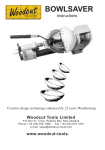
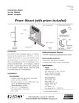
PEC Code: 5331-001
COM Code: 408184109
Model: LU1WVCH
1W Tapped Horn Loudspeaker
Description
Horn speakers produce high sound levels and are capable of covering large, noisy areas. Minimum effective mounting height for
a horn is 15 feet; 20 feet is preferable. However, in a system with talk-back (hands-free answer back), the speaker may have to
be mounted as low as 8 to 12 feet and set at a lower power setting.
CAUTION: Do not connect more than two (2) speakers per talk-back zone.
Speakers must be mounted in locations that provide a clear sound path to the area paged. Avoid placing speakers in front of
shelves, partitions, or other obstructions.To avoid feedback, do not place telephones near speaker installation.
CAUTION: The 1-Watt Tapped Horn Loudspeaker is not compatible with any 70- or 25-volt line audio distribution products.
Various power outputs can be easily selected on the speakers using the rotary power switch.
Speaker Installation
Mounting
1. Loosen the wing nut and remove the tapered locking pin. A light tap on the end of the pin may be required to free it.
2. Mount the bracket using appropriate hardware (not supplied). It can be mounted either to a pole using a band slot or to a flat
surface using the 3 holes in its base (see Figure 1).
3. Position the horn for sound direction and hand tighten the wing nut. A 45o downward angle is recommended, but this may vary
depending upon speaker layout. Unless otherwise indicated, do not aim speakers directly at each other or poor paging
intelligibility may occur.
CAUTION: When positioning the speaker, the mounting bracket will bind if the wing nut and its tapered locking pin are not
sufficiently loosened. Forcing the horn will damage the mounting bracket. Be certain that the wing nut is loose and that the tapered
pin is free before trying to adjust the position of the horn.
4. Reattach the horn and the bracket by reversing the mounting procedure.
MOUNTING ON POLE
MOUNTING
BRACKET
WINGNUT
MOUNTING ON FLAT SURFACE
Figure 1
TAPERED
LOCKING
PIN
METAL BANDING
TAPE (NOT
PROVIDED)
WING NUT
MOUNTING BRACKET
Page 1 of 2
Issue 1, October 1999
54-2012-01 Printed in USA 9910
© 1999 Bogen Communications Inc. All rights reserved.
Specifications subject to change without notice.
Wire Connections
The speaker has screw-type terminals, which are protected by a clear plastic cover. The cover also acts as a strain
relief for the wires after they are connected. The procedure for connecting the speaker is given in the following
steps:
Figure 2
VOLUME LEVEL
C O NTRO L
(USE ONLY SETTINGS
1 TO 4)
TERMINALS
1. Loosen the screws that hold the plastic cover and
swing the cover out of the way.
2. Make the connections and dress the wire as shown in
Figure 2.
3.When using shielded speaker wire, and wiring from
speaker to speaker, wire the shield drains to provide a
continuous shield to the next speaker. Otherwise, clip the
shield wire at the point it emerges from the main cable.
The shield wire should never be terminated on the
speaker.
SPEAKER CABLE
4. Do not replace the plastic cover until final power
adjustments have been made.
Note: Use 22 AWG shielded, twisted
pair on all wire runs. Com Code:
401882956. Pec Code: 2734-SPK.
Note: When connecting from speaker to speaker, the
speaker must be kept in phase.This means that all
number 1 (-) terminals must connect on the same
wire, and all number 2 (+) terminals must be
connected on the other wire.
Final Power Adjustments
1. Ensure that the speaker is set to its lowest setting (this will prevent an excessively loud page when first used).
2.While a page is in process, adjust the volume control with a screwdriver. Turn clockwise to increase the volume (see table
below).
3. Install the plastic cover.
Impedance and Power Output
3.4 Vrms Input
Switch Setting
Impedance (Ω)
Power (W)
SPL (dB)
1
720
0.016
89
2
180
0.063
95
3
45
0.25
101
4
10
1.0
107
Page 2 of 2