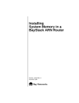
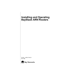
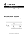
1
BCC Quick Reference
Getting Started
The Bay Command Console (BCC™) uses a hierarchical tree configuration model similar to a DOS hierarchy of
directories and files. The tree contains:
•
•
Objects: Physical or logical entities you can configure. An ethernet interface or the protocol ip is an object.
Each object that you configure has a unique BCC identifier, for example, ethernet/2/1 or ip/1.2.3.4/255.0.0.0.
Parameters: Describe characteristics and behavior of an object; for example, slot, connector, and bofl are
parameters of ethernet. Each parameter has a value: slot 4, connector 1, and bofl off are parameter-value
pairs.
Sample Configuration
rip
ip address 1.2.3.4 mask 255.0.0.0
(AN/BN/ARN)
box#
ethernet slot 2 connector 1 (AN/BN/ARN)
ethernet slot 2 module 2 connector 1 (ASN/System 5000)
stack#
(ASN/System 5000)
ethernet slot 2 connector 2 (AN/BN/ARN)
ethernet slot 1 module 2 connector 2 (ASN/System 5000)
ip address 2.3.4.5 mask 255.0.0.0
rip
The boldface labels in the figure are the BCC commands used to create this configuration.
Proceed as follows to start using the BCC:
•
•
•
•
•
To enter BCC configuration mode, type config at the bcc> prompt.
To see any commands that you can enter next at the current prompt, enter the question mark (?) command.
To see usage (syntax) or options for a specific command, add the question mark (?) to that command,
for example: ethernet ? or show ? or show ip routes ?
To configure any object available at your current location in the tree, enter the object name (such as
ethernet).
Note: Carefully follow the syntax and details of any BCC usage Help prompting you for more complete
information. Note especially where you can insert slash (/) characters.
To see parameter values for the object you just configured, enter info.
•
To see all values for any parameter configurable from your current context, enter <parameter> ?,
for example, in an ethernet context, enter bofl ?
•
•
To see statistical information, enter show commands in any BCC mode. (First enter show ?)
To see the entire device configuration, enter show config -all
•
•
•
•
To see an explanation of all options for show config, enter show config ? or help show config
To list objects already configured at the next (branch) level of the device configuration tree, enter lso
To move one level back toward the root level of the device configuration, enter back
To move back to root (box# or stack#) level from any location in the device configuration tree, enter box
(AN/ANH, ARN, BN) or stack (ASN or System 5000).
To see your current location in the device configuration, enter pwc (print working context).
To exit configuration mode, type exit. To exit the BCC and return to the Technician Interface prompt, type exit
again. To log out of the router, type logout.
•
•
Part Number 305418-B Rev 00
Configuration Tips
•
You immediately modify device behavior when you enter BCC configuration commands.
•
Configure physical interfaces first, add protocols to each interface, and then configure global (device-wide)
protocols. Some protocols have global as well as interface-level objects.
•
A configured object has a BCC identifier that uses slash characters to join the name of the object to the values
of its required parameters, for example, ethernet/2/1 or ip/1.2.3.4/255.0.0.0. The identifier of the object you
just configured or accessed appears in the BCC configuration prompt.
•
When you add IP to an interface, the BCC accepts either a decimal mask value (such as 24, indicating the
number of bits reserved for the network portion of the IP address) or a value in dotted-decimal notation, such
as 255.255.255.0. Regardless of mask input format, the BCC always displays a configured mask in
dotted-decimal notation.
•
To see every object that you can configure from your current location, enter help tree. The output is in
hierarchical or tree format. (The closer you are to root level, the greater the amount of output.) To see the
entire configurable tree for a device, enter help tree -all
•
To access any object already configured, type the path to that object. For example, to access RIP on an
Ethernet interface, type eth 2/1;ip 1.2.3.4/255.0.0.0;rip (the BCC interprets each semicolon [ ; ] as if you had
pressed the Return key to start a new command line).
•
If you exit and then reenter the BCC without rebooting the router, configuration changes that you made during
the last BCC session are still in effect.
Common BCC Operations
The BCC indicates when configuration parameters have values that are required (you must supply a value). Other
parameters have derived or default values supplied by the system.
Task
BCC Command Syntax
Examples
At the box# prompt, use either of the following
formats:
<interface_type> slot <slot> connector <connector>
<interface_type> <slot>/<connector>
ethernet slot 3 connector 1
eth 3/1
Configure a physical interface.
•
•
For AN, ARN, BN:
For ASN and System 5000:
At the stack# prompt, use either of the following
formats:
<interface_type> slot <slot> module <module>
connector <connector>
<interface_type> <slot>/<module>/<connector>
ethernet slot 1 module 1 connector 2
eth 1/1/2
Configure a global or
interface-level protocol:
<protocol> <required_parameter> <value> ...
ip address 1.2.3.4 mask 255.0.0.0
ip 1.2.3.4/255.0.0.0
ip address 1.2.3.4 mask 24
ip 1.2.3.4/24
Modify parameter values.
<parameter> <new_value> ...
cache-size 64
ca 64
disable
Disable, enable, or delete the
current object (the object named enable
delete
in the current prompt).
Disable, enable, or delete this
child of the current object (an
object configured below the
current object).
2
disable [<BCC_instance_id>]
enable [<BCC_instance_id>]
delete [<BCC_instance_id>]
ip/1.2.3.4/255.0.0.0# disable
ip/1.2.3.4/255.0.0.0# enable
ip/1.2.3.4/255.0.0.0# delete
fddi/1/1# disable ip/1.2.3.4/255.0.0.0
fddi/1/1# enable ip/1.2.3.4/255.0.0.0
fddi/1/1# delete ip/1.2.3.4/255.0.0.0
Part Number 305418-B Rev 00
Command Shortcuts
•
•
To recall any command from the history list, press the up arrow (or Control-p) or down arrow (or Control-n).
Enter the first few letters of any command and press Return. The BCC automatically completes any command
for which it finds a unique match in the current context. Otherwise, the BCC displays choices or an error
message based on your partial entry.
Help Tips
•
To see an overview of the Help system, enter help or help help
•
To see a list of all system (nonconfiguration) commands, enter help commands or help commands -more
•
To see Help for a specific command, enter help <command>, for example, help compact or help ip
•
To see text definitions for the parameters of any object configurable at your current location in the tree, enter
help <parameter> (for example, help bofl) or enter help <object_name> (for example, help ip)
•
When the BCC displays a list of choices for help on a configuration object, copy and paste the command line
that best describes the path from root to that object in the tree, for example, help box ip (global IP) or for
interface IP, help box ethernet ip or help box serial ppp ip
Interface Conventions
The following table describes the conventions for slot, module, and connector numbering on each router platform.
Platform
Syntax
AN/ANH
<interface> <slot> <connector>
• <interface> = interface type: ethernet, token-ring, serial, etc.
• <slot> = 1 (The AN/ANH is a single-slot device.)
• <connector> numbering starts with connector 1.
Example:
ethernet slot 1 connector 3
This is an Ethernet interface configured on AN/ANH connector 3, which exists on an Ethernet adapter module.
(Connectors 1 and 2 are on the base module.)
ARN
<interface> <slot> <connector>
• <interface> = interface type: ethernet, token-ring, serial, etc.
• <slot> = 1 (The ARN is a single-slot device.)
• <connector> numbering depends on the port type (LAN or WAN). LAN connector numbering starts at 1 on
the base module, which contains only LAN ports, and continues in ascending order, starting with the first
LAN port on an ARN expansion module. (The ARN expansion module plugs into the ARN base module.)
WAN connector numbering starts with connector 1 on WAN adapter module 1, continues with connector 2
on WAN adapter module 2, and ascends sequentially with WAN connectors 3 through n on the ARN
expansion module.
Adapter modules
Expansion module
U
1
ISDN BRI
withNT1
D
B1
DD
B2
COM3
RLSD3
COM4
COM5
RLSD4
RLSD5
Serial
COM
2
Tx
RLSD
Serial
10BaseT
AUI
Run
Pwr
Base
Expansion
Boot
RPS
Adapter1
DCM
Fail
Fan
Adapter2
PCMCIA
Rx
Cl
Ethernet 1
BayStack
Advanced Remote Node
Base module
Example:
ethernet slot 1 connector 2
This interface is configured on LAN connector 2, which exists physically on an Ethernet expansion module.
(Ethernet connector 1 is on the base module.)
Example:
serial slot 1 connector 3
This is a serial (WAN) interface configured on WAN connector 3 on the ARN expansion module.
Part Number 305418-B Rev 00
3
Platform
Syntax
ASN
<interface> <slot> <module> <connector>
• <interface> = interface type: ethernet, token-ring, serial, etc.
• <slot> = 1, 2, 3, or 4, depending on the setting of the module ID switch on each ASN.
• <module> numbering corresponds to net module numbering (1 through 4) on each ASN.
• <connector> numbering starts at 1 on each net module (per media type).
Example:
ethernet slot 2 module 3 connector 2
This is an Ethernet interface on connector 2 of net module 3, in ASN 2 of a stacked ASN configuration.
BN
<interface> <slot> <connector>
• <interface> = interface type: ethernet, token-ring, serial, etc.
• <slot> = 2 through 5 (BLN) or 1 through 14 (BCN).
• <connector> numbering starts with connector 1 on each slot (per media type).
Example:
ethernet slot 8 connector 3
This is an Ethernet interface configured on connector 3 of slot 8 of a BCN router.
System 5000 <interface> <slot> <module> <connector>
• <interface> = interface type: ethernet, token-ring, serial, atm, etc.
• <slot> = 2 through 13 in a System 5000 chassis.
• <module> numbering corresponds to net module 1 or 2, which plugs into a System 5000 base module.
A System 5000 base module is always module 3.
• <connector> numbering starts at 1 on each net module. The base module always contains a connector 1,
which plugs into a System 5000 backplane (for example, Ethernet, token ring, or ATM backplane).
Example:
ethernet slot 2 module 2 connector 1
This is an Ethernet interface on connector 1 of the Ethernet net module (module 2) in slot 2.
atm slot 2 module 3 connector 1
This is an ATM interface on connector 1 of slot 2, a Model 5782 Virtual Network Router (VNR) base module
(module 3). Note that the VNR does not accommodate any net modules.
Sample Session
The BCC syntax required to enter the sample configuration shown in the figure on page 1 would be as follows on a BN
router that has an Ethernet module in slot 2:
Configuration Command
Comment
box# ethernet slot 2 connector 1
Configures ethernet 2/1, using a fully specified interface
location.
ethernet/2/1# ip 1.2.3.4/8
Configures ip/1.2.3.4, using a decimal mask value.
ip/1.2.3.4/255.0.0.0# rip
Configures rip/1.2.3.4, with no parameter values required.
rip/1.2.3.4# back
Navigates back one level closer to box or root level.
ip/1.2.3.4/255.0.0.0# back
(Same as above.)
ethernet/2/1# back
(Same as above.)
box# eth 2/2
Configures ethernet 2/2, using abbreviated format. No slash
between the object name and the first required parameter
value. Slashes between required values only.
ethernet/2/2# ip address 2.3.4.5 mask 255.0.0.0 Configures ip/2.3.4.5, using dotted-decimal notation for the
mask value.
ip/2.3.4.5/255.0.0.0# rip
Configures RIP on ip/2.3.4.5.
rip/2.3.4.5# box
Jumps to root level from any location in the configuration tree.
Notice how each BCC prompt contains the BCC identifier of the object just configured. Slash (/) characters join the
object name and any required parameter values in the identifier of a configured object.
4
Part Number 305418-B Rev 00