1
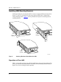
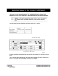
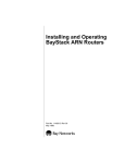
Part No. 116950-A Rev. A
Technical Notice
Corrections to Installing and Operating
BayStack ARN Routers
This notice provides corrected information on:
•
Service Console Signals and Pin Assignments
•
Installing ARN Mounting Brackets
•
Operation of Fan LED
Service Console Signals and Pin Assignments
Table C-12 in Installing and Operating BayStack ARN Routers incorrectly lists the
connector pin assignments for the local terminal service console port. (Table C-13
correctly lists the connector pin assignments for the modem service console port.)
Table 1 shows correct signal and pin assignments for the local console port.
Table 1.
Local Console Port DB-9 Pin Assignments
Pin Assignment
Pin 1
Pin 9
Pin No.
Signal Name
Direction
1
Not Used
N/A
2
TXD (Transmit data)
To terminal
3
RXD (Receive data)
From terminal
4
Not Used
N/A
5
Ground
N/A
6
DTR
To terminal
7
Not Used
N/A
8
Not Used
N/A
9
Not Used
N/A
Bay Networks, Inc., Corporate Headquarters
4401 Great America Parkway, Santa Clara, CA 95054
8 Federal Street, Billerica, MA 01821
Part No. 116950-A Rev. A
Installing ARN Mounting Brackets
The flange brackets for mounting the ARN in a rack now support additional rack positions.
Figures 1-1 and 1-2 in Installing and Operating BayStack ARN Routers illustrate the
wrong mounting bracket. Figure 1 correctly illustrates the options for attaching the new
mounting brackets.
B1
ISDN BRI
withNT1
1
2
DD
B1
B2
ISDN BRI
withNT1
1
2
RLSD
DD
B2
RLSD
Screws
(4 places)
Screws
(4 places)
1
Screws
(4 places)
2
ARN0004A
Figure 1.
Attaching Brackets to Rack-Mount the ARN
Operation of Fan LED
Table 3-1 in Installing and Operating BayStack ARN Routers incorrectly describes the Fan
LED as an indicator of normal operation. The amber Fan LED actually indicates failure; it
lights if one or more cooling fan stops operating.
2