1
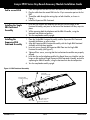
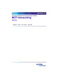
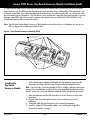
Avaya 3900 Series Key-Based Accessory Module Installation Guide
This document describes how to install the Key-Based Accessory Module (KBA) (NTMN37xx) for the 3900 Series
Digital Deskphones. The KBA provides 22 additional line/feature keys for the 3904 and the 3905 telephones. You
can add a second KBA, for a total of 44 additional line/feature keys. In addition to the KBA, you will need to order
the Key-Based Accessory Module Kit 1 (NTMN38AA), which includes the Single KBA Footstand Assembly. If you are
adding a second KBA, you will also need to order the Key-Based Accessory Module Kit 2 (NTMN38BA), which
includes the Expansion KBA Footstand Assembly.
Note: The KBA and Display-Based Accessory (DBA) modules are mutually exclusive. A telephone with one or two
KBAs configured or installed cannot have a DBA.
Figure 1: Key-Based Accessory Module (KBA)
Plug cable into10-pin
connection port
Clips
ACM
connection
port
Tilt handles
553-9538
Installing the
Key-Based
Accessory Module
1. While depressing the telephone tilt handle, pull the telephone away from the
footstand until it clears the final stop. Gently pull the footstand off the clips.
Note: If an Accessory Connection Module (ACM) is installed, unplug the ACM and
remove it from the footstand. Install the ACM in the Single KBA Footstand Assembly.
See the “Accessory Connection Module Installation Guide” for detailed instructions.
2. Place the telephone and the KBA face down on a non-abrasive surface, and
align them.
3. Plug the cable from the Module into the 10-pin connection port on the
telephone.
4. Thread the cable through the opening in the side of the telephone.
5. Install the Single KBA Footstand Assembly. See “Installing the Single KBA
Footstand Assembly” on page 2.
N0023535
1 of 3
Standard 2.00
Avaya 3900 Series Key-Based Accessory Module Installation Guide
Add a second KBA
1. Place the telephone and the two KBAs face down on a non-abrasive surface.
2. Plug the cable from the second KBA into the 10-pin connection port on the first
KBA.
3. Thread the cable through the routing clips on both Modules, as shown in
Figure 1.
4. Install the Expansion KBA Footstand.
Installing the Single
KBA Footstand
Assembly
1. Insert the clips on both the telephone and the KBA into the hinges on the
Footstand Assembly, and press on the front of the footstand until they snap into
place.
2. While squeezing both the telephone and the KBA tilt handles, swing the
footstand into the desired position.
3. Turn the completed assembly upright.
Installing the
Expansion KBA
Footstand Assembly
1. Place the Single KBA Footstand Assembly and the Expansion KBA Footstand
Assembly face down on a flat surface.
2. Align the Expansion KBA Footstand Assembly with the Single KBA Footstand
Assembly and slide them together.
3. Insert two screws through the Expansion KBA Plate into the Single KBA
Footstand Assembly (see Figure 2).
4. Tighten all four screws, ensuring that the two footstand assemblies are properly
aligned.
5. Insert the clips on the telephone and the Key-Based Accessory Modules into the
hinges on the combined Single/Expansion KBA Footstand Assembly, and while
squeezing the KBA tilt handles, swing the footstand into the desired position.
6. Turn the completed assembly upright.
Figure 2: KBA Footstand Assembly
Single KBA
Footstand Assembly
Expansion KBA
Footstand Assembly
Tighten
these screws
Standard 2.00
Install and tighten
these screws
Expansion KBA Plate
2 of 3
N0023535
Avaya 3900 Series Key-Based Accessory Module Installation Guide
Configuring
the Meridian 1
for the KBA in
LD 11
Prompt
Response
Description
…
KBA
…
…
(0)-2
…
Number of KBAs (0) = default
Note 1: KBA appears when the telephone type is 3904 or 3905.
Note 2: Each KBA provides 22 additional line/feature keys. These additional keys are
configured in LD 11. Key numbers associated with the first KBA are 32-53. Key numbers
for the second KBA are 54-75.
Configuring
the MSL-100
for the KBA in
Servord
Prompt
Response
Description
DN_OR_LEN
x…x
x…x = Enter either a DN or an LEN
OPTKEY
1
Option key
OPTION
KBA
Key-based Accessory Module
KBA_COUNT
1-2
Number of KBAs
ADO
Note: Each KBA provides 22 additional line/feature keys. These additional keys are
configured in Servord. Key numbers associated with the first KBA are 33-54. Key numbers
for the second KBA are 55-76.
N0023535
3 of 3
Standard 2.00