1
efesotomasyon.com - Control Techniques,emerson,saftronics -ac drive-servo motor
efesotomasyon.com - Control Techniques,emerson,saftronics -ac drive-servo motor
Introduction
Introduction
Thank you for purchasing option OPC-VG7-UPAC (hereinafter referred to as UPAC) and OPC-VG7-SI
(hereinafter referred to as Optical Link) of Fuji’s general-purpose vector inverter FRENIC 5000 VG7S
(hereinafter referred to as VG7S).
This User’s Manual describes the procedure for operating VG7S using UPAC only or UPAC and Optical
Link. Read through this User’s Manual for correct operation.
This manual is prepared for those familiar with the operation methods of the D300win software and
VG7S hardware. Therefore the operation method of each piece of software and the unit itself is not
described in this manual. Refer to the following relevant manuals together with this manual.
Reference document
1
High performance vector
control inverter
FRENIC5000VG7S Series
2
Instruction manual
FRENIC5000VG7S
3
4
FRENIC5000VG7S
USER’S MANUAL
User’s manual for MICREXSX Series SPH, instruction
volume
Reference
document No.
Remarks
MEH405
Catalog
INR-HF51306-E
Instruction manual attached to product
Description concerning test operation
and connection only (attached to
purchased product)
MEH407
Main manual for VG7S
Explanation of memory, language,
system definition and other items of
MICREX-SX Series
Explanation of basic operation of
D300win and programming and
monitoring methods of MICREX-SX
Series
Description of menus and icons of
D300win and explanation of all
operation methods
FEH200
5
User’s manual for MICREXSX Series SPH, <elementary
volume> for D300win
FEH250
6
User’s manual for MICREXSX Series SPH, <reference
volume> for D300win
FEH254
(1) No part of this manual may be reproduced or transmitted without the prior permission from
the publisher.
(2) Description in this manual is subject to change for improvement without prior notice.
(3) Though description in this manual is carefully prepared, contact our sales outlet for any
uncertainties or errors.
* Microsoft and Windows are registered or mere trademarks of Microsoft Corp.
* Intel 486 and Pentium are registered or mere trademarks of Intel Corp.
1
efesotomasyon.com - Control Techniques,emerson,saftronics -ac drive-servo motor
Introduction
This product is an optional unit for variable speed operation of the three-phase induction motor. Before
using our product, read through “Safety Precautions” for correct operation.
As well, ensure that these “Safety Precautions” are delivered to the final person in charge of maintenance.
Safety Precautions
Read this manual carefully before installing, connecting (wiring), operating, servicing, or inspecting the
inverter.
Familiarize yourself with all safety features before using the inverter.
In this manual, safety messages are classified as follows:
Improper operation may result in serious personal injury or death.
WARNING
Improper operation may result in slight to medium personal injury or property
damage.
Situations more serious than those covered by CAUTION will depend on prevailing circumstances.
Always follow instructions.
CAUTION
Instructions on use
WARNING
• This inverter is designed to drive a 3-phase induction motor and is not suitable for a single-phase
motor or others, as fire may result.
• This inverter may not be used (as is) as a component of a life-support system or other medical
device directly affecting the personal welfare of the user.
• This inverter is manufactured under strict quality control standards. However, safety equipment
must be installed if the failure of this device may result in personal injury and/or property damage.
There is a risk of accident.
Instructions on installation
CAUTION
• Mount this inverter on an incombustible material such as metal.
There is a risk of fire.
• Do not place combustible or flammable material near this inverter, as fire may result.
• The inverter housed in IP00 (18.5kW or over) should be installed in a place where no one can touch
it easily.
Electric shock or injury may result.
CAUTION
• Do not hold or carry this inverter by the surface cover. Inverter may be dropped causing injury.
• Ensure that the inverter and heat sink surfaces are kept free from foreign matter (lint, paper dust,
small chips of wood or metal chips), as fire or accident may result.
• Do not install or operate a damaged inverter or an inverter with missing parts, as injury may result.
• When changing installation bracket position, use the attached screws, as injury may result.
2
efesotomasyon.com - Control Techniques,emerson,saftronics -ac drive-servo motor
Instructions on wiring
WARNING
• Connect the inverter to power via a line-protection molded-case circuit breaker or earth-leakage
circuit breaker, as fire may result.
• Use the cables of the specified size, as fire may result.
• Always connect a ground wire, as electric shock or fire may result.
• A licensed specialist must perform the wiring works, as electric shock may result.
• Turn off the power before starting the wiring work, as electric shock may result.
• Wire the inverter after installation is complete, as electric shock or injury may occur.
• Do not supply power to any inverter of which parts are broken, omitted, or damage in
transportation, as electrical shock or fire may result.
CAUTION
• Confirm that the phases and rated voltage of this product match those of the AC power supply, as
injury may result.
• Do not connect the AC power supply to the output terminals (U, V, and W), as injury may result.
• Do not connect a braking resistor directly to the DC terminals (P(+) and N(−)), as fire may result.
• When using DC power input, ensure that the fan power switching connector (CNRXTX) is correctly
engaged in the inverter as a trouble may occur.
• When using DC power input of 18.5kW or larger inverter, be sure to connect AC power to terminals
R0 and T0 for a power supply of fan as a trouble may occur.
• Ensure that the noise generated by the inverter, motor, or wiring does not adversely affect peripheral
sensors and equipment, as accident may result.
3
efesotomasyon.com - Control Techniques,emerson,saftronics -ac drive-servo motor
Introduction
Instructions on operation
WARNING
• Be sure to install the surface cover before turning on the power (closed). Do not remove the cover
while power to the inverter is turned on.
Electric shock may occur.
• Do not operate switches with wet hands, as electric shock may result.
• When the retry function is selected, the inverter may restart automatically after tripping. (Design
the machine to ensure personal safety in the event of restart)
Accident may result.
• When the torque limiting function is selected, operating conditions may differ from preset
conditions (acceleration/deceleration time or speed). In this case, personal safety must be assured.
Accident may result.
• As the STOP key is effective only when a function setting has been established, install an
emergency switch independently, and when an operation via the external signal terminal is
selected, the STOP key on the keypad panel will be disabled.
Accident may result.
• As operations start suddenly if alarm is reset with a running signal input, confirm that no running
signal is input before resetting alarm.
Accident may result.
• When an alarm is activated, the motor coasts. If the motor needs to be stopped in such a case, install
a brake to the machine with the motor.
Accident may result.
• If AUTO RESTART is selected in the restart mode after momentary power failure (function code
F14), the inverter restarts automatically starting the motor rotation when the power is recovered.
Accident may result.
• When the tuning (function code H01) is started, the motor, machine or equipment starts and stops
repeatedly. Ensure safety before performing tuning.
Accident may result.
• If the user set the function codes wrongly or without completely understanding this user’s manual,
the motor may rotate with a torque or at a speed not permitted for the machine.
Accident or injury may result.
• Do not touch inverter terminals when energized even if inverter has stopped.
Electric shock may result.
CAUTION
• Do not start or stop the inverter using the main circuit power.
Failure may result.
• Do not touch the heat sink or braking resistor because they become very hot.
Burns may result.
• As the inverter can set high speed operation easily, carefully check the performance of motor or
machine before changing speed settings.
Injury may result.
• Do not use the inverter braking function for mechanical holding.
Injury may result.
• During pre-excitation, the speed adjuster does not function and the motor may be rotated by load
disturbance. When using pre-excitation, therefore, also use the mechanical brake.
Injury may result.
• If improper data is set at the function code related with speed adjuster as in the case of setting high
gain abruptly, the motor may hunt.
Injury may result.
4
efesotomasyon.com - Control Techniques,emerson,saftronics -ac drive-servo motor
Instructions on maintenance, inspection, and replacement
WARNING
• Wait a minimum of five minutes (15kW or less) or ten minutes (18.5kW or more) after power has
been turned off (open) before starting inspection. (Also confirm that the charge lamp is off and that
DC voltage between terminals P(+) and N(−) does not exceed 25V.)
Electric shock may result.
• Only authorized personnel should perform maintenance, inspection, and replacement operations.
(Take off metal jewelry, such as watches and rings. Use insulated tools.)
Electric shock or injury may result.
Instructions on disposal
CAUTION
• Treat as industrial waste when disposing it.
Injury may result.
Other instructions
WARNING
• Never modify the product.
Electric shock or injury may result.
Conformity to Low Voltage Directive in Europe
CAUTION
• The contact capacity of alarm output for any fault (30A, B, C) and relay signal output (Y5A, Y5C)
is 0.5A at 48V DC.
• The inverter must be securely grounded. Besides installation of the earth leakage circuit breaker
(ELCB), this grounding work is necessary for protection against electrical shock.
• Use a crimp terminal to connect a cable to the main circuit terminal or inverter ground terminal.
• Use a single cable to connect the z G inverter ground terminal. (Do not connect two or more
cables to the inverter ground terminal.)
• Use a molded-case circuit breaker (MCCB) and magnetic contactor (MC) that conform to EN or
IEC standards.
• Use the inverter under over-voltage category III conditions and maintain Pollution degree 2 or
better as specified in IEC664. To maintain Pollution degree 2 or more, install the inverter in the
control panel (IP54 or higher level) having structure free from water, oil, carbon, dust, etc.
• For the input-output wiring of the inverter, use cable (diameter and type) as specified in Appendix
C in EN60204.
• To ensure safety, install an optional AC reactor, DC REACTOR, or external braking resistor as
follows:
1) Install inside an IP4X cabinet or barrier if electrical parts are exposed.
2) Install inside an IP2X cabinet or barrier if electrical parts are not exposed.
General Instructions
Although figures in this manual may show the inverter with covers and safety screens removed for
explanation purposes, do not operate the device until all such covers and screens have been replaced.
5
efesotomasyon.com - Control Techniques,emerson,saftronics -ac drive-servo motor
Introduction
Warning label positions
Inverter with a small capacity (15kW or lower)
Inverter with a middle capacity (18.5kW or higher)
6
efesotomasyon.com - Control Techniques,emerson,saftronics -ac drive-servo motor
Inside the inverter
7
efesotomasyon.com - Control Techniques,emerson,saftronics -ac drive-servo motor
Introduction
1. Preparation of System and Startup ・・・・・ 1-1
1.1 System Configuration of UPAC・・・・・・・・・ 1-1
1.1.1 System Configuration ・・・・・・・・・・・・・・ 1-1
1.1.2 Requirements of PC ・・・・・・・・・・・・・・・ 1-3
1.2 Preparation of Option ・・・・・・・・・・・・・・・・・ 1-4
1.2.1 OPC-VG7-UPAC Option・・・・・・・・・・・・ 1-4
1.2.2 OPC-VG7-SI Option ・・・・・・・・・・・・・・・ 1-13
1.3 Preparation of Software ・・・・・・・・・・・・・・・ 1-22
1.3.1 Installation Method ・・・・・・・・・・・・・・・・ 1-22
1.3.2 Changing the Program ・・・・・・・・・・・・・ 1-30
1.3.3 Uninstalling ・・・・・・・・・・・・・・・・・・・・・・・ 1-31
1.3.4 Starting D300win ・・・・・・・・・・・・・・・・・・ 1-35
2. Preparation and Basic Operation
Examples・・・・・・・・・・・・・・・・・・・・・・・・・・・・・・ 2-1
2.1 Examination of System ・・・・・・・・・・・・・・・ 2-1
2.1.1 Application to Small to Medium
Systems ・・・・・・・・・・・・・・・・・・・・・・・・・ 2-1
2.1.2 Examination of Specification ・・・・・・・・ 2-3
2.2 Individual Operation of UPAC ・・・・・・・・・・ 2-5
2.2.1 Preparation ・・・・・・・・・・・・・・・・・・・・・・・ 2-5
2.2.2 Settings on VG7S Side ・・・・・・・・・・・・・ 2-6
2.2.3 Settings on D300win Side ・・・・・・・・・・ 2-9
2.3 Operation of Multiple Units via
Optical Option (OPC-VG7-SI) ・・・・・・・・・・ 2-14
2.3.1 Preparation ・・・・・・・・・・・・・・・・・・・・・・・ 2-14
2.3.2 Setting the Function Code ・・・・・・・・・・ 2-16
2.3.3 Connection ・・・・・・・・・・・・・・・・・・・・・・・ 2-18
2.4 Basic Operation Examples ・・・・・・・・・・・・ 2-19
2.4.1 Determination of Specification ・・・・・・・ 2-19
2.4.2 Creating a Program ・・・・・・・・・・・・・・・・ 2-19
2.4.3 Downloading・・・・・・・・・・・・・・・・・・・・・・ 2-25
2.4.4 Simulating and Monitoring ・・・・・・・・・・ 2-28
3. VG7 Interface・・・・・・・・・・・・・・・・・・・・・・・・・・ 3-1
3.1 Memory Interface ・・・・・・・・・・・・・・・・・・・・ 3-1
3.1.1 Giving Basic Commands ・・・・・・・・・・・ 3-1
3.1.2 Referencing or Updating
Function Codes ・・・・・・・・・・・・・・・・・・・ 3-8
3.1.3 Operating Inputs and Outputs ・・・・・・・ 3-11
3.1.4 Monitoring Data ・・・・・・・・・・・・・・・・・・・ 3-18
3.1.5 Using Pulse Data ・・・・・・・・・・・・・・・・・・ 3-24
3.1.6 Dynamic Speed Change・・・・・・・・・・・・ 3-30
3.1.7 Speed Simulation・・・・・・・・・・・・・・・・・・ 3-33
3.2 Application Creation Examples ・・・・・・・・・ 3-35
3.2.1 Pattern Operation Example ・・・・・・・・・ 3-35
3.2.2 Position Control Example
Using Pulse String・・・・・・・・・・・・・・・・・・ 3-36
3.2.3 Example of Dancer Control ・・・・・・・・・ 3-38
3.3 VG7S Control Block Diagram List ・・・・・・・3-40
3.3.1 Operation Command ・・・・・・・・・・・・・・・3-40
3.3.2 Speed Command Selection Section ・・3-41
3.3.3 Acceleration/deceleration Calculation,
Speed Limit, Position Control Input
Section ・・・・・・・・・・・・・・・・・・・・・・・・・・・3-42
3.3.4 Motor Speed and Line Speed
Detection ・・・・・・・・・・・・・・・・・・・・・・・・・3-43
3.3.5 Pulse Train Reference Input Section
and Position Detection Section・・・・・・・3-44
3.3.6 Speed Control and Torque Reference
Section ・・・・・・・・・・・・・・・・・・・・・・・・・・・3-45
3.3.7 Torque Limit, Torque Current
Reference and Magnetic Flux
Reference Section ・・・・・・・・・・・・・・・・・3-46
3.3.8 Current Control and Vector Control
Section ・・・・・・・・・・・・・・・・・・・・・・・・・・・3-47
3.3.9 Function Code Writing Permission
and Saving ・・・・・・・・・・・・・・・・・・・・・・・3-48
4. Packaged Software ・・・・・・・・・・・・・・・・・・・・・4-1
4.1 WPS-VG7-DAN ・・・・・・・・・・・・・・・・・・・・・・4-1
4.1.1 Examination of System ・・・・・・・・・・・・・4-2
4.1.2 Control Block Diagrams・・・・・・・・・・・・・4-4
4.1.3 Function Code・・・・・・・・・・・・・・・・・・・・・4-6
4.2 WPS-VG7-POS ・・・・・・・・・・・・・・・・・・・・・・4-21
4.2.1 Examination of System ・・・・・・・・・・・・・4-22
4.2.2 Basic Connection Diagram ・・・・・・・・・・4-27
4.2.3 Control Block・・・・・・・・・・・・・・・・・・・・・・4-29
4.2.4 Function Code・・・・・・・・・・・・・・・・・・・・・4-30
4.2.5 Preparation for Operation ・・・・・・・・・・・4-31
4.2.6 Control Command ・・・・・・・・・・・・・・・・・4-33
4.2.7 ORT Stopping Action ・・・・・・・・・・・・・・・4-35
4.2.8 Input/Output Specification ・・・・・・・・・・・4-39
4.2.9 Troubleshooting ・・・・・・・・・・・・・・・・・・・4-42
4.3 WPS-VG7-TEN ・・・・・・・・・・・・・・・・・・・・・・4-43
4.3.1 System Consideration・・・・・・・・・・・・・・・4-44
4.3.2 Input/Output Standard Interface
(single inverter is used) ・・・・・・・・・・・・4-45
4.3.3 How to Adjust ・・・・・・・・・・・・・・・・・・・・・・4-47
4.3.4 Parameter Description ・・・・・・・・・・・・・・4-48
4.3.5 Table for Setting Relevant Parameters
・・・・・・・・・・・・・・・・・・・・・・・・・・・・・・・・・4-54
4.3.6 Calculation Control Block Diagrams ・・・4-56
5. UPAC Programming Specification・・・・・・・5-1
5.1 Performance Specification ・・・・・・・・・・・・・5-1
5.2 Memory ・・・・・・・・・・・・・・・・・・・・・・・・・・・・・5-3
5.2.1 Memory Map ・・・・・・・・・・・・・・・・・・・・・・5-3
5.2.2 Input/output Address Assignment ・・・・5-16
5.2.3 Function Code Area Address
Assignment ・・・・・・・・・・・・・・・・・・・・・・・5-31
5.2.4 Option Monitor Area Address
Assignment ・・・・・・・・・・・・・・・・・・・・・・・5-59
5.2.5 User Application RAS Area Address
Assignment ・・・・・・・・・・・・・・・・・・・・・・・5-59
efesotomasyon.com - Control Techniques,emerson,saftronics -ac drive-servo motor
6. Maintenance and Inspection ・・・・・・・・・・・ 6-1
6.1 General Inspection Items・・・・・・・・・・・・・・ 6-1
6.1.1 Inspection Interval ・・・・・・・・・・・・・・・・・ 6-1
6.1.2 Inspection Item・・・・・・・・・・・・・・・・・・・・ 6-1
6.2 Battery Change ・・・・・・・・・・・・・・・・・・・・・・ 6-2
6.2.1 Batter Changing Procedure ・・・・・・・・・ 6-2
efesotomasyon.com - Control Techniques,emerson,saftronics -ac drive-servo motor
efesotomasyon.com - Control Techniques,emerson,saftronics -ac drive-servo motor
efesotomasyon.com - Control Techniques,emerson,saftronics -ac drive-servo motor
1. Preparation of System and Startup
1.1 System Configuration of UPAC
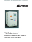
1.1.1 System Configuration
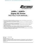
Install D300win + UPAC Upgrade to the PC to use it as a programming tool for the VG7S + UPAC + SI
system shown below.
In the system without OPC-VG7-SI, one VG7S unit can be controlled by UPAC.
Optical cable with
connector
(accessory)
Loop connection
High speed
counter position
command/
detection
Extended DI/DO
RS485
connector on
control PCB
OPCVG7-DIO
OPCVG7-SI
OPCVG7-PG
Extended AI/AO
OPCVG7-SI
OPCVG7-AIO
OPCVG7-SI
OPC-VG7-UPAC
Master and slave units : Max. 12
Broadcasting units
: Max. 156
FRENIC5000VG7S
FRENIC5000VG7S
FRENIC5000VG7S
Lithium primary battery
Special connection cable
NP4H-CNV (with converter)
2m
Printer
cable
NP4H-SEDV2
- D300win system disk
- Standard extension FB disk
- D300win <Reference volume>
Printer
RS232c
Install
D300win
system
PC
(Windows95/98/NT)
+
VG7S
CD-ROM
WPS-VG7-PCL
- UPAC Upgrade (free of charge)
Mouse
Fig. 1-1-1
1-1
efesotomasyon.com - Control Techniques,emerson,saftronics -ac drive-servo motor
Table 1-1-1 Option card and other system component list
Division
Digital card
(For 16-bit bus)
Name
Model
Technology card
High-speed optical
link card
DIO expansion card
Digital card
(For 8-bit bus)
AIO expansion card
RS485 expansion
card
OPC-VG7-RS
D300win system
software
Cable
UPAC communication system
(Unnecessary for single-unit
control)
OPC-VG7-AIO
PG expansion card
Application
package software
OPC-VG7-SI
OPC-VG7-DIO
T link I/F card
System package
software
OPC-VG7-UPAC
Application
High-performance PLC
controller
For expansion of DI/DO = 16/10 Expand for I/O.
For expansion of AI/AO = 2/2
Expand for I/O.
Use the expansion card when the
built-in RS485 terminal is occupied
for another application.
When sharing the purpose with, for
example, an external PLC for general
control and UPAC for driving control
For connection of POD
OPC-VG7-TL
For connection with MICREX
(PLC)
OPC-VG7-PG
High-speed counter
Position command and position
detection
For Windows
While the inverter support loader is
provided with charge, the UPAC
Upgrade only is provided without
charge.
Programming tool
-
Software for tension
control
Software for dancer
control
Software for position
control
Expand when necessary.
For Windows
NP4H-SEDV2
UPAC Upgrade
Remarks
One accessory lithium primary
battery
Expanded when controlling multiple
units
Optical cable (5 m) with connector
per each option
(For wiring length longer than 5 m,
contact us.)
WPS-VG7-TEN
WPS-VG7-DAN
Package software group
operating on UPAC
WPS-VG7-POS
Loader cable
2 m; use marketed RS 232C cable
for additional length.
(On NPH4-CNV side: D subminiature
9-pin female connector)
For downloading and
monitoring
NP4H-CNV
Limitations for installation of UPAC and SI options
There are limitations for simultaneous installation, as shown in the table below.
OK: Can be installed simultaneously.
NG: Cannot be installed simultaneously.
Table 1-1-2
SN
FV
AIO
DI
DIO
PG/PGo
TL
SI(UPAC)
SI(MWS)
RS
PMPG/
PMPGo
UPAC
SX
OPEN
SN
FV
AIO
DI
DIO
NG
NG
NG
OK
OK
OK
OK
OK
OK
OK
OK
NG
NG
OK
OK
OK
OK
OK
OK
OK
OK
NG
OK
OK
OK
OK
OK
OK
OK
OK
OK
OK
OK
OK
OK
OK
OK
OK
OK
OK
OK
OK
OK
OK
OK
PG/
PGo
OK
OK
OK
OK
OK
OK
OK
OK
OK
OK
OK
OK
Being Being Being Being Being Being
develop- develop- develop- develop- develop- developed
ed
ed
ed
ed
ed
Being Being Being Being Being Being
develop- develop- develop- develop- develop- developed
ed
ed
ed
ed
ed
TL
SI
SI
(UPAC (MWS)
NG
OK
OK
OK
OK
NG
NG
OK
OK
NG
NG
NG
OK
NG
OK
NG
OK
OK
NG
RS
NG
OK
PMPG/
PMPGo
UPAC
OPEN
NG
OK
OK
NG
Being
Being
NG
develop- developed
ed
Being
Being
Being Being Being
develop- develop- develop- develop- developed
ed
ed
ed
ed
1-2
SX
NG
NG
NG
efesotomasyon.com - Control Techniques,emerson,saftronics -ac drive-servo motor
1. Preparation of System and Startup
1.1.2 Requirements of PC
1.1.2.1 Hardware
To run D300win and UPAC Upgrade on the PC, the following hardware requirements must be satisfied.
• IBM-compatible PC, DOS/V PC or PC98 series PC equipped with Intel Pentium (233 MHz or faster,
recommended)
• Windows VGA, resolution 800 x 600 dots minimum (SVGA, resolution 1024 x 768 dots,
recommended)
• 32 MB or more RAM
• 220 MB or more free space on hard disk. However, the necessary hardware space varies according to
the installed program. (D300win system software: 100 MB minimum, standard expansion FB package:
120 MB minimum)
• 3.5” floppy disk drive (1.44 MB format floppy can be read and written)
• CD-ROM drive
(For PCs without CD-ROM drive, contact us. The UPAC Upgrade software is provided on a floppy
disk.)
• Mouse
• RS232C serial port (D subminiature 9-pin specification, selection from 4,800 to 38,400 bps)
• Printer port (Used to print program documents, etc.)
1.1.2.2 Software
To operate D300win and UPAC Upgrade on a PC, one of the following operating systems is necessary.
• Microsoft Windows 95/98 (English or Japanese)
• Microsoft Windows NT V4.0 (English or Japanese)
(Operation on Windows 3.1 or Windows NT V3.5x is not guaranteed.)
1-3
efesotomasyon.com - Control Techniques,emerson,saftronics -ac drive-servo motor
1.2 Preparation of Option
1.2.1 OPC-VG7-UPAC Option
1.2.1.1 Description of product
This card (User Programmable Application Card, UPAC hereafter) is an optional card for the inverter
control installed on FRENIC5000VG7S (VG7S hereafter). This card gives you an additional higher level
control over your inverter. You can also use engineering support tool D300win to facilitate programming
the control applications being used for this card.
UPAC is an optional PLC card integrated into the inverter conforming to MICREX-SX series high
performance CPU module (NP1PS-32). Since UPAC is slightly different in programming specification
such as memory map and available instructions from that for the high performance CPU module, refer to
"5) Programming Specifications" for more information. We recommend you to refer to "MICREX-SX
Series USER’S MANUAL–INSTRUCTIONS" when you design your application program.
n Main features
(1) Application execution function
Executes an application program
Controls tasks for application program (default, fixed period, event)
(2) Support tool interface
RS485 (included in UPAC-VG7S connection bus) 1 channel
(3) RAS functions
Executes self-diagnosis and notifies to the inverter.
(4) Other
Data memory backup with battery
This card enables you to realize controls such as dancer control, tension control, and orientation control
easily.
With inverter link option (OPC-VG7-SI), you can designate an inverter with UPAC installed as a
master and connect up to twelve slave inverters (156 inverters for broadcasting) to control these
individual inverters.
An application program of UPAC runs at minimum execution period of 1ms. The execution period
increases to 2, 3, 4, ... or 32000ms depending on the size of a program.
You can assign up to 64W from static variables used in an application program to the function codes U01
to U64 (user area) of VG7. When you assign parameters for adjustment to this user area, you can use the
KEYPAD panel of VG7 to refer to or change the data without personal computer.
UPAC has some restrictions over SX series high performance CPU module (NP1PS-32). The calendar
function is not available and SX specific instructions are removed. Read this document thoroughly for
complete understanding.
[Limitations]
UPAC is equipped with a high-performance CPU installed in MICREX-SX, but the functions of UPAC
are not fully equivalent. There are limitations in the following functions.
• Calendar and clock function
Because of this, nothing is displayed in the “major failure time information” and “power shutdown
history information” of detail RAS.
The calendar/clock function of D300win always shows “January 01, 1970, 00:00:00.”
• Because UPAC is not equipped with the key switch of MICREX-SX, the key state is always “TERM.”
• HELP of UPAC system definition of D300win is not supported.
• “MICREX-SX” is displayed as the title of each dialog box of D300win.
• Battery change in the live-line state is impossible.
1-4
efesotomasyon.com - Control Techniques,emerson,saftronics -ac drive-servo motor
1. Preparation of System and Startup
1.2.1.2 Specifications
Table 1-2-1 Performance
Item
Instruction
Memory capacity
Language
Speed
Program
memory
Data memory
Control
function
elements
No. of I/O points
VG7S control
variables
Task
Level types
Priority
Number
Cause of
interruption
Fixed period
cycle
Cause of task
start
Default
task execution
PG number
Length per POU
Operation
nesting
FB·FCT
numbers
Memory backup
specification
Note (restrictions)
8KW
32KW for MICREX-SX series
NP1PS-32
Timer
:256 points
Counter
:128 points
Differential relay :256 points
Hold relay
:256 points
Max. 302W
6 unit system :50W×6 units+2W
12 unit system :22W×12 units+2W
0, 1, default level
0>1>default level
3
Constant period, event
Integer multiple of fixed cycle interruption up to
32000ms
Up to two
Fixed cycle interruption from
VG7S. Period is adjustable
through loader.
Based on interrupt, executed in a period
rounded up according to task execution time.
Example) Executed in 3ms cycle where
interrupt is 1ms and task execution
period is 2.3ms.
64
Max.4k steps
Max.1024
System FCT
System FB
User FCT·FB
nesting
Loader interface
Specification
IEC language compliant (IEC61131-3)
Sequence instruction
: 0.12µs min.
Integer addition/subtraction instructions
: 0.14µs min.
Multiplication instruction : 0.16µs min.
Division instruction
: 1.94µs min
Floating point addition/subtraction instructions
: 0.18µs min.
Multiplication instruction : 0.18µs min.
Division instruction
: 1.4µs min.
Timer instruction
: 1.0µs
(CAL/RET processing included)
Counter instruction
: 0.7µs
(CAL/RET processing included)
32k steps
185 types (such as transmission, string,
analog, and 32 or more bit operation)
28 types (such as flip-flop, timer, counter, file,
analog, and pulse)
User FCT
User FB
Max.128-2
256
256
Transmission
specification
Transmission
rate
Transmission
distance
Isolation
Backup area
Back up period
RS485
4 line type
38400bps,19200bps,9600bps,4800bps
Calendar, message, and
BANK_CHG available for
MICREX-SX series NP1PS32 are not available.
128 nestings including task
switch available
Max. 10m
None
Retention area
5 years (storage temperature: 25°C)
1-5
Battery replacement is not
available under hot-line
conditions.
efesotomasyon.com - Control Techniques,emerson,saftronics -ac drive-servo motor
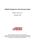
1.2.1.3 External dimensions and accessories
14
60.5
15
10
37
25
6.6
1
A
B
C
D
E
EP4197-C
NO.
Lithium
battery
DATE
5
φ10
51
37.5
4
MADE IN JAPAN
CN1
4
15
3
113
72
65
2
6-φ3.6
5
OPC-VG7-UPAC
40
6
10.5
CN2
5
40
6.5
111.5
Fig. 1-2-1
10.5
CN2
Table 1-2-2 Backup battery (accessory)
Item
Model
Classification of battery
Nominal voltage
Guaranteed life of
battery
Dimensions
Mass
Specification
NT8P-BT
Lithium primary battery (Do not charge.)
DC3.6V
5 years (ambient temperature: 25 °C)
(Note)
φ14.5 x 24.5, cable length 50 mm
About 10g
Battery connection connector
Main body of battery
Fig. 1-2-2
Note: This guarantee period is that of the discrete battery. The guaranteed period of the battery is five years at 25 °C even if it is
stored as a spare part. The memory backup time varies according to the ambient temperature and the device to which the
battery is installed. The backup time decreases to a half as the ambient temperature rises by 10 °C.
1) Receiving inspection
After the product is delivered, check the following items.
(1) Check that the delivered item is the ordered one. Check the model printed on the option.
Nomenclature of model: OPC-VG7-UPAC
Name of option. UPAC → UPAC Option
Name of inverter to which the option is installed.
VG7 → FRENIC 5000 VG7S
1-6
efesotomasyon.com - Control Techniques,emerson,saftronics -ac drive-servo motor
1. Preparation of System and Startup
(2) Check for damage given during transportation.
(3) Check if all the accessories are contained.
Accessories: 5 spacers
1 M3 screw
1 backup battery (installed to product)
CAUTION
• Do not operate the product with damaged or missing parts.
Otherwise injuries or material losses may be caused.
1.2.1.4 Operating environment
Operate the option in the same environment as that of the main body of VG7S.
Table 1-2-3 Operating environment
Item
Specification
Site
Indoors
Ambient
-10 to +50°C
temperature
Relative humidity
5 to 95% (no dew)
Atmosphere
Free from dust, direct sunshine, corrosive gases, oil mist, vapor or
water drops.
Little salt inclusion.
No dew or icing caused by abrupt temperature changes.
Altitude
1000 m maximum
Vibration
5.9 m/s2 [0.6 G] maximum
Note: Failure to satisfy the above environmental conditions will cause poor performance, reduced life and failures.
Checkup of ROM version of main body
CAUTION
• Some of options are not compatible with VG7S of early ROM versions. Correct operation is not
ensured with early versions. Be sure to check the ROM version in the maintenance information
given at the keypad panel. If the version is uncertain, contact us.
Check the ROM version of the main body before installing the option.
If the option is already installed, check the ROM version of the main body in the
1500
state.
To check, view the information displayed on the right of “MAIN” and “MTR” in MAIN=H1xxxx
MTR =H2xxxx
the maintenance information of the keypad panel.
KP =K xxxx
The screen shown on the right is displayed on page five of the maintenance
information. Press the ∨ key of the keypad panel to open page five.
Table 1-2-4
Model of option
OPC-VG7-UPAC
ROM version
MAIN
MTR
H1003D or later
H2003D or later
1-7
efesotomasyon.com - Control Techniques,emerson,saftronics -ac drive-servo motor
1.2.1.5 Storage
1) Temporary storage
Store the option in the environment specified in Table 1-2-5.
Table 1-2-5 Storage environment
Item
Specification
Ambient temperature
-10 to +50°C
Without dew or icing caused by abrupt
Storage temperature (Note 1) -25 to +65°C
temperature changes
Relative humidity
5 to 95% (Note 2)
Free from dust, direct sunshine, corrosive gases, flammable
gases, oil mist, vapor, water drops or vibration.
Atmosphere
Little salt inclusion
Note 1: The storage temperature indicates the allowable temperature in a short period such as during transportation.
Note 2: Even if the humidity satisfies the rating, dew or icing is caused in a site subject to large temperature changes. Avoid
such sites.
(1) Do not place the option on the floor. Place it on a table or in a shelf.
(2) To store in an adverse atmosphere, wrap the option in a vinyl sheet, packing polyethylene film, or
the like.
(3) If there is danger of humidify effects, place a drying agent (silica gel, etc.) inside before packing in
the procedure specified in (2).
2) Storage in extended period
The storage method for storing the option for a long time after purchasing, varies substantially
according to the environment of the storage site.
Clarify the concrete environmental specification and contact your dealer or nearest Fuji Electric’s
sales outlet to obtain advice for assured storage methods.
Generally, observe the following precautions.
(1) Satisfy the requirements for temporary storage.
(2) Carefully pack to avoid intrusion of moisture or the like. Place a drying agent (silica gel, etc.) in
the package. The amount of the drying agent may comply with JIS Z 0301 (Method of moistureproof packaging). The target relative humidity inside the package is 70%.
When leaving this option in VG7S installed to a unit or control panel, especially at a site under
construction, the equipment is often exposed to moisture and dust. If this is the case, remove the
option together with VG7S and store in preferable environment described in the operation manual.
1-8
efesotomasyon.com - Control Techniques,emerson,saftronics -ac drive-servo motor
1. Preparation of System and Startup
1.2.1.6 Installation method
1) Notes on handling
CAUTION
Avoid the following in installation and operation.
They may cause damage, malfunction or failure.
(1) Do not drop or turn over.
(2) Do not install where large vibration is
present.
(4) Do not install in the same panel where
high voltage (3000V, 6000V or more)
devices are installed.
(5) Do not use the power supply provided for
devices generating excessive noise.
(6) Do not operate with high temperature and
high humidity or low temperature.
(Do not operate under a condition where
rapid humidity change causes
condensation)
Operating ambient temperature
0 to 55°C
Operating ambient humidity
20 to 95%(No
condensation)
(3) Do not install where corrosive gas is
present.
1-9
efesotomasyon.com - Control Techniques,emerson,saftronics -ac drive-servo motor
2) Before starting installation
(1) Confirmation of product
When unpacking the delivered product, make sure of the following items.
1) Check if the product is what you have ordered.
2) Check if the product is free from damage.
3) Check if all the accessories (spacers, screws, and battery. The battery is connected to the
product.) are delivered.
CAUTION
• The product may be broken due to inadequate work during installation or removal.
• Before installing or removing the option, turn the inverter off and check that the CHARGE lamp is
unlit. Even if all the main circuit, control and auxiliary power supply of the inverter are turned off,
control terminals 30A, 30B, 30C, Y5A and Y5C of the inverter are live when the external control
circuit is powered by another power supply.
• Turn the external power supply off to avoid electric shock.
(2) Outline of installation
To install, open the front cover and tighten screws.
Refer to the next page and thereafter for details.
Control PCB
Connector
Connector
UPAC
* With the main body rated at 18.5 kW or above
Fig. 1-2-3
Remove the front cover, install the option, then install the cover.
1-10
efesotomasyon.com - Control Techniques,emerson,saftronics -ac drive-servo motor
1. Preparation of System and Startup
(3) How to remove the front cover
Remove the front cover from the main body as shown in the figure below. Be careful that the
removal method varies according to the applicable inverter model (capacity).
Applicable inverter model (capacity)
FRN15VG7S-2/4 (15 kW) or less
Applicable inverter model (capacity)
FRN18.5VG7S-2/4 (18.5 kW) or more
Loosen the two surface cover installation
screws at part a shown in Fig. 1-2-4 and hold
the upper part of the surface cover to remove it.
(1) As shown in Fig. 1-2-5, remove the
surface cover installation screws (the
quantity varies according to the capacity)
to remove the surface cover.
(2) Remove the two screws at part c to
remove the keypad panel.
(3) Remove the two screws at part d to
remove the keypad panel case.
b
c
d
a
Keypad panel
Keypad panel case
Control PCB
Fig. 1-2-4 Front cover removal method
(FRN15VG7S-2/4 (15 kW) or less)
Fig. 1-2-5 Front cover removal method
(FRN18.5VG7S-2/4 (18.5 kW) or more)
1-11
efesotomasyon.com - Control Techniques,emerson,saftronics -ac drive-servo motor
(4) Option installation method
Follow the procedure below to install the option. When using the option with another option, refer
to the installation procedure and operation manual attached to the other option.
1) Install the option to fit it into the connector (CN10) on the control PCB.
2) Install the five spacers and one M3 screw attached to the option into the option installation holes
as shown in the figure below.
3) Connect the battery connector to CN2.
4) Referring to “(3) How to remove the front cover,” reverse the removal procedure to reinstall the
front cover.
Spacers
OPC-VG7-UPAC
M3 screw
Battery
CN2
CN10
Control PCB
Fig. 1-2-6 Option installation method
CAUTION
• An ErA alarm may be developed when the option is turned on for the first time. If this happens,
leave the power turned on for about 30 seconds then turn the power off, and turn it on again.
1-12
efesotomasyon.com - Control Techniques,emerson,saftronics -ac drive-servo motor
1. Preparation of System and Startup
1.2.2 OPC-VG7-SI Option
1.2.2.1 Description of product
The UPAC option is designed for a small to medium system for generalizing and
driving about 10 inverters.
UPAC is installed on an arbitrary VG7S inverter. As a means to control the second
and later VG7Ss from UPAC, this optical option OPC-VG7-SI (hereinafter
referred to as optical option) is necessary.
Rigid digital system configured through optical communication
In conventional small to medium systems, a PLC, computer board or the like is
installed externally and each inverter is generalized and driven through
input/output basis or analog basis. When network connection is possible, digital
control via the network (including open and private ones) can be made.
Using this optical option, the control based on inputs and outputs or analog signals
can be replaced with a rigid high-speed maintenance-free digital system where a
small wiring length can result in a reduced cost and noise immunity is high.
Load distribution system
The UPAC control group can be placed as a subordinate system in a system where the host PLC or
computer board takes charge of generalization and control of each driving control group. In this system,
the load of the CPU can be reduced and a distributed system consisting of host and subordinate devices
can be configured. High-response control dedicated to the driving control becomes possible in the
subordinate system and the CPU of the host can be dedicated to generalization and control of various data
sent from each driving control group.
Here, preparation for operation of multiple inverters using a link (optical link) connected via optical fiber
cable (hereinafter referred to as optical cable) with UPAC being the master, is described, for customers
having purchased the optical option of the FRENIC 5000 VG7S inverter.
Read through this manual carefully before operating because there are some limitations in operation.
1-13
efesotomasyon.com - Control Techniques,emerson,saftronics -ac drive-servo motor
1.2.2.2 Specifications
Table 1-2-6 Hardware specifications
Item
Model
Connector
Definition
Power supply
Accessory
Specification
Remarks
Optical option
(High-speed serial link)
OPC-VG7-SI
Transmission (TX) / reception (RX) connector
Define “SI (UPAC)” using SW 1 and SW 2 on the option.
(SW1, SW2) = (ON, OFF)
The power is supplied through the connector.
Plastic optical fiber cable (5 m)
Communication specifications
Item
Connection style
Communication
speed
Communication
distance
Connection
method
Number of
connected
inverters
Writing time
Communication
link
establishment
confirmation
Protective
function
Fail-soft
operation
Specification
Loop-back connection through plastic optical fiber cable
4Mbps
Max. extension distance: 20 m (distance between adjacent inverters)
For systems exceeding 20 m, contact us.
Master-slave method (Max. 12 units)
Broadcasting method (Max. 156 units)
Master-slave method
6-unit system: Max. 6 units (50 W inputs/outputs per unit)
12-unit system: Max. 12 units (22W inputs/outputs per unit)
Broadcasting method
Max. 156 units (32 W outputs per unit)
Master-slave method
Time = (n-1) x 2 (ms)
(n: n > 1; number of units)
2 units: 2 ms
3 units: 4 ms
4 units: 6 ms
5 units: 8 ms
Broadcasting method:
* The reading period is
6 units: 10 ms
1 ms
twice the value
7 units: 12 ms
written on the left.
8 units: 14 ms
9 units: 16 ms
10 units: 18 ms
11 units: 20 ms
12 units: 22 ms
Blinking green LED on option
The digital output indicates the communication state.
Inverter being stopped;
The protective function does not work if the communication link is not
established.
Inverter running;
Protective function “inverter-to-inverter link error” is developed if the
communication link is not established.
Remarks
The accessory cable attached to
the product is 5 m long.
Selection with function code
Selection in D300win screen.
The “broadcasting method”
indicates the function where the
same data is written from the
master to all inverters.
The lamp blinking at 500 ms
interval indicates establishment
of the communication link.
[0-D07] is used: “1” indicates
establishment of the
communication link.
The conditions for failure of
establishment of the
communication link are:
- Illegal setting (function code,
System Definition)
- Broken wire in communication
link (broken wire, bending at 35
mm or a smaller curvature, etc.)
The option is not compatible with degeneracy operation.
→ When inverters are connected via optical link in a system consisting of
total n units (2 ≤ n ≤ 156: n is an integer), the communication link is lost if
x (1 ≤ x ≤ n-1: x is an integer) units of inverters are turned off. Turn on all
n units of inverters (or control power of the inverters).
Software specifications
Item
ROM version
Definition of
connection
Specification
H10060 or later, H20060 or later
Operate at the above ROM versions. (Use the I/O check at the keypad
panel to check the ROM version).
- Master-slave function code o35, o36
- o36 set only at master
Master-slave method
I/Q area; selection between 50W and 22W
Function code area;
All codes can be read or written only at the master inverter (equipped
Input/output data
with UPAC). Only the 4W function code data can be written at the slave
inverter.
Broadcasting method
Q area only; 32W (Only the master can refer to 18W in the I area.)
1-14
Remarks
If these settings are wrong, the
communication link is not
established.
Selected in 6-/12-unit system
With the broadcasting method,
only the output selection of
inverter 1 of a 6-unit system can
be used.
efesotomasyon.com - Control Techniques,emerson,saftronics -ac drive-servo motor
1. Preparation of System and Startup
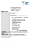
1.2.2.3 External dimensions and accessories
Unit: mm
Fig. 1-2-7 External dimensions of option PCB
Plastic optical fiber cable
5m
Connector with a locking
mechanism (gray)
Optical plastic cable
Fig. 1-2-8 Plastic optical fiber cable
1-15
Connector with a locking
mechanism (dark brown)
efesotomasyon.com - Control Techniques,emerson,saftronics -ac drive-servo motor
1) Receiving inspection
When the product is delivered, check the following items.
(1) Check if the product is what you have ordered. Check the model printed on the option.
Nomenclature of model: OPC-VG7-SI
SI → Optical ink option
Name of option
(Abbreviation of Serial Interface)
Name of inverter to which VG7 → FRENIC5000VG7S
the option is installed
(2) Check if the product is damaged during transportation.
(3) Check that all the accessories are included.
3 spacers
3 screws (M3)
1 plastic optical fiber cable (for transmission and reception)
CAUTION
• Do not use the option with damaged or missing parts.
• Otherwise injuries or material losses may be caused.
1.2.2.4 Operating environment
Use the option in the same environment as that of the VG7S main body.
Table 1-2-7 Operating environment
Item
Site
Ambient temperature
Relative humidity
Atmosphere
Altitude
Vibration
Specification
Indoors
-10 to +50°C
5 to 95% (no dew)
Free from dust, direct sunshine, corrosive gases, oil mist, vapor or water drops.
Little salt inclusion.
No dew or icing caused by abrupt temperature changes.
1000 m maximum
5.9 m/s2 [0.6 G] maximum
Note: Failure to satisfy the above environmental conditions will cause poor performance, reduced life and failures.
Checkup of ROM version of main body
CAUTION
• Some of options are not compatible with VG7S of early ROM versions. Correct operation is not
ensured with early versions. Be sure to check the ROM version in the maintenance information
given at the keypad panel. If the version is uncertain, contact us.
Check the ROM version of the main body before installing the option.
1500
If the option is already installed, check the ROM version of the main body in the
state.
MAIN=H1xxxx
MTR =H2xxxx
Check the ROM version of the main body of VG7 (not optical option or keypad
KP =K xxxx
panel).
To check, view the information displayed on the right of “MAIN” and “MTR” in
the maintenance information of the keypad panel.
The screen shown on the right is displayed on page five of the maintenance information. Press the ∨
key of the keypad panel to open page five.
1-16
efesotomasyon.com - Control Techniques,emerson,saftronics -ac drive-servo motor
1. Preparation of System and Startup
Table 1-2-8
Model of option
OPC-VG7-SI(UPAC)
ROM version
MAIN
MTR
H10060 or later
H20060 or later
1.2.2.5 Storage
1) Temporary storage
Table 1-2-9
Item
Ambient temperature
Storage temperature (Note 1)
Relative humidity
Atmosphere
Specification
-10 to +50°C
Without dew or icing caused by
-25 to +65°C
abrupt temperature changes
(Note 2)
5 to 95%
Free from dust, direct sunshine, corrosive gases, flammable
gases, oil mist, vapor, water drops or vibration.
Little salt inclusion
Note 1: The storage temperature indicates the allowable temperature in a short period such as during transportation.
Note 2: Even if the humidity satisfies the rating, dew or icing is caused in a site subject to large temperature changes. Avoid such
sites.
(1) Do not place the option on the floor. Place it on a table or in a shelf.
(2) To store in an adverse atmosphere, wrap the option in a vinyl sheet, packing polyethylene film, or
the like.
(3) If there is danger of humidify effects, place a drying agent (silica gel, etc.) inside before packing in
the procedure specified in (2).
2) Storage in extended period
The storage method for storing the option for a long time after purchasing, varies substantially
according to the environment of the storage site.
Clarify the concrete environmental specification and contact your dealer or nearest Fuji Electric’s
sales outlet to obtain advice for assured storage methods.
Generally, observe the following precautions.
(1) Satisfy the requirements for temporary storage.
(2) Carefully pack to avoid intrusion of moisture or the like. Place a drying agent (silica gel, etc.) in
the package. The amount of the drying agent may comply with JIS Z 0301 (Method of moistureproof packaging). The target relative humidity inside the package is 70%.
When leaving this option in the inverter installed to a unit or control panel, especially at a site under
construction, the equipment is often exposed to moisture and dust. If this is the case, remove the
option together with the inverter and store in preferable environment described in the inverter
operation manual.
1-17
efesotomasyon.com - Control Techniques,emerson,saftronics -ac drive-servo motor
1.2.2.6 Installation method
CAUTION
• The product may be broken due to inadequate work during installation or removal.
• Before installing or removing the option, turn the inverter off and check that the CHARGE lamp is
unlit. Even if all the main circuit, control and auxiliary power supply of the inverter are turned off,
control terminals 30A, 30B, 30C, Y5A and Y5C of the inverter are live when the external control
circuit is powered by another power supply.
• Turn the external power supply off to avoid electric shock.
There are the following limitations in installation of the option.
K If the option is for a slave unit in an inverter without OPC-VG7-UPAC, refer to [1) Installation
method on slave side] to install on either installation position (CN2 on the left side or CN3 on the
right side) on the control PCB. However, when the analog option is installed, too, be sure to install the
option on the CN2 side and install the analog option on the CN3 side.
K If the option is for a master unit in an inverter with OPC-VG7-UPAC, refer to [2) Installation method
on master side] to install on either installation position (CN2 on the left side or CN3 on the right side)
on the control PCB.
1) Installation method on slave side
(For slave unit in inverter with OPC-VG7-UPAC)
(Installation to CN2 on left side)
(1) Install the three accessory spacers g to the
option installation fittings (a, b and c) on the
control PCB.
(2) Install the option so that the connector
(CN1; on the back) of the option fits the
connector (CN2) on the control PCB.
(3) Tighten the three accessory screws h in the
installation holes of the option to fix the
option.
(4) While referring to “How to remove the front
cover,” reverse the removal procedure to
reinstall the front cover.
(Installation to CN3 on right side)
(1) Install the three accessory spacers g to
the option installation fittings (d, e and
f) on the control PCB.
(2) Install the option so that the connector
(CN1; on the back) of the option fits the
connector (CN3) on the control PCB.
(3) Tighten the three accessory screws h in
the installation holes of the option to fix
the option.
(4) While referring to “How to remove the
front cover,” reverse the removal
procedure to reinstall the front cover.
h
h
Option
g
g
CN2
a
bc
f
Control PCB
Fig. 1-2-9 Option installation method
(Installation to CN2)
d
e
CN3
Fig. 1-2-10 Option installation method
(Installation to CN3)
1-18
efesotomasyon.com - Control Techniques,emerson,saftronics -ac drive-servo motor
1. Preparation of System and Startup
2) Installation method on master side (Installation of option in inverter with OPC-VG7-UPAC)
11.4
13.0
CAUTION
• The spacer that comes with the option slightly differs from that attached to OPC-VG7-UPAC. Use
the spacers correctly as described in the following procedure.
The product may be broken if they are used incorrectly.
Spacer attached to option
Spacer attached to OPC-VG7-UPAC
(Installation to CN3 on right side)
(1) Install OPC-VG7-UPAC to the connector
(CN10) on the control PCB.
(2) Install the five spacers h and one screw i
attached to OPC-VG7-UPAC, to the
installation holes (a, b, c, d, e and f) of
OPC-VG7-UPAC, and install the one spacer
j attached to the option, to the option
installation fitting (g) on the control PCB, as
shown in Fig. 1-2-12.
(3) Install the option so that the connector
(CN1) of the option fits the connector (CN3)
of the control PCB.
(4) Tighten the accessory three screws k to the
installation holes of the option to fix the
option.
(5) While referring to “How to remove the front
cover,” reverse the removal procedure to
reinstall the front cover.
(Installation to CN2 on left side)
(1) Install OPC-VG7-UPAC to the connector
(CN10) on the control PCB.
(2) Install the five spacers h and one screw i
attached to OPC-VG7-UPAC, to the
installation holes (a, b, c, d, e and f) of
OPC-VG7-UPAC, as shown in Fig. 1-211, and fix them.
(3) Install the option so that the connector
(CN1; on the back) of the option fits the
connector (CN2) on the control PCB.
(4) Tighten the three accessory screws k to the
installation holes of the option to fix the
option.
(5) While referring to “How to remove the
front cover,” reverse the removal
procedure to reinstall the front cover.
k
k
Option
h
i
a
d
c
b
e
f
h
Unit: mm
OPC-VG7-UPAC
CN2
i
j
a
d b e
c
f
CN3
g
CN10
CN10
Control PCB
Fig. 1-2-11 Option installation method
(Installation to CN2)
Fig. 1-2-12 Option installation method
(Installation to CN3)
1-19
efesotomasyon.com - Control Techniques,emerson,saftronics -ac drive-servo motor
1.2.2.7 Confirmation and setting procedures
1) Confirmation, connection and setting of optical option
Perform the following setting and connection.
(1) Set the rotary switch (SW1) on the optical option. Master = 0, each slave = 1.
(2) Check the setting of DIP switch SW2. (SW 2-1, SW 2-2) = (ON, ON) fixed.
(3) Connect the optical cable attached to the optical option (5-meter long, one cable attached to each
optical option).
2) Switch setting
CAUTION
• If the settings of the switches (SW 1 and SW 2) on the optical option are wrong, the UPAC system
does not operate correctly. Read the following description about the setting carefully and set
correctly.
• Turn the power (control power) off before changing the switch setting. If the switch setting is
changed with the power ON, turn the power off then on again to reset.
Table 1-2-10 Switch on card (SW1)
SW1
setting
Part No.
0
Master
1
Slave
1 to 11
2 to 9
Invalid
SW1 rotary switch
7 8
5 6
9 0 1
4
Function
Remarks
Define the inverter, on which UPAC is installed, to be the
master.
If “0” is set for an inverter without UPAC, operation
procedure alarm “Er6” is caused.
Set all the slaves at “1.”
If the switch is set at other than “1,” operation procedure
alarm “Er6” is caused.
Do not set in these positions. Otherwise operation procedure
alarm “Er6” is caused.
Set the station switch of the master at “0” and that of all the slaves at “1.”
The station with SW 1 being 0 is defined to be the master, while that with
SW 1 being 1 is defined to be a slave.
2 3
Fig. 1-2-13
Table 1-2-11 Switch on card (SW 2)
SW 2-1
SW 2-2
Part No.
setting
setting
OFF
OFF
ON
OFF
SW 2 DIP
OFF
ON
switch
ON
1 2
OFF
ON
Function
UPAC +
SI system
Remarks
Do not set.
These settings are used for definition of
other applications and therefore no warning
is displayed.
The optical option is sued in the UPAC
system.
DIP switch shown on the left is located at the lower end of the option. Be sure to set the
two elements at ON.
After the above settings are given, the optical option becomes available as a UPAC
system.
Fig. 1-2-14
1-20
efesotomasyon.com - Control Techniques,emerson,saftronics -ac drive-servo motor
1. Preparation of System and Startup
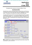
3) Connection of optical cable
CAUTION
• If the optical cable is bent at a curvature smaller than 35 mm for a long time, optical
communication does not function correctly and inverter-to-inverter link error “Erb” is caused.
Avoid routing the cable at curvatures smaller than 35 mm.
OPC-VG7-SI
Slave
Dark brown
(Reception)
OPC-VG7-SI
Master
Gray
(Transmission)
Dark brown
(Reception)
SW1
7 8
5 6
R-2528 T-1528
4
9 0 1
5 6
7 8
R-2528 T-1528
2 3
4
Gray
(Transmission)
SW1
9 0 1
2 3
Connect the optical option via the accessory
optical cable.
As shown in the figure on the right, the
connectors for transmission and reception
are located at the lower end of the optical
option. Each connector is identified with the
color. Connect the gray plug with the gray
connector, and the dark brown plug with the
dark brown connector.
Configure a loop when connecting. The
communication originated at the master is
sent to a slave and the communication sent
from the slave is received at the adjacent
slave. The communication received at the
last slave is sent and returns to the master in
the connection pattern.
Dark brown
(Reception)
Gray
(Transmission)
Dark brown
(Reception)
Gray
(Transmission)
Fig. 1-2-15
Table 1-2-12 Optical connector on SI card
Part No.
Name
Color
T-1528
TX
Gray
R-2528
RX
Dark brown
Outline
Transmitter (transmission)
Receiver (reception)
Notes: If the optical cable is not connected or it is inserted improperly, correct communication is impossible.
• If the communication link fails due to a broken line in the communication path under power
application, an inverter-to-inverter link error “Erb” is caused.
• If the communication link is not established when power is turned on, the communication link is
not established but no alarm is displayed. When an operation command is issued, an inverter-toinverter link error “Erb” is caused as a protective action.
Table 1-2-13 Absolute maximum rating of optical cable (accessory)
Item
Min.
Max.
Unit
Remarks
Storage temperature range
-40
+75
°C
Tensile force
50
N
Within 30 minutes
Failure to operate within one hour; an
10
Short-time bending radius
mm
inverter-to-inverter link error “Erb” is
caused.
A curvature shorter than 35 mm for a
long time may cause an inverter-to35
Long-time bending radius
mm
inverter link error “Erb.” Be sure to
assure 35 mm or a larger curvature.
Tensile strength (long time)
1
N
Bending at 90 ° on 10 mm mandrel
Flexibility
1000 times
(core rod, spindle)
Impact test as per MIL-1678, Method
Impact
0.5
Kg
2030, Procedure 1
Guaranteed minimum value due to
Guaranteed minimum
20
m
distance
transmission loss (0 to 70 °C)
Weight
4.6
g/m
* Plastic optical cable made by Mitsubishi Rayon (accessory)
1-21
efesotomasyon.com - Control Techniques,emerson,saftronics -ac drive-servo motor
1.3 Preparation of Software
1.3.1 Installation Method
1.3.1.1 Installing the D300win software package
The D300win software package is delivered in multiple floppy disks. Installation disks contain an install
program which automatically proceeds necessary actions for installation, icon registration and so on.
When installation is made via a network, copying or installation may not proceed correctly according
to some network environment and operating environment.
(1) Inactivate the virus detection software and screen saver.
(2) Select [Control Panel (C) ...] from the [Settings (S) ...] submenu in the [Start] menu of Windows
95/98/NT4.0. (The case of Windows 98 is described in the following description as a typical
example.)
(3) Double-click the left mouse button on the “Add/Remove Programs” icon in the “Control Panel” dialog
box.
(4) Click the left mouse button on the [Install (I) ...] button.
(5) Insert the System Disk No. 1 containing the install program into the floppy disk drive.
(6) Click the left mouse button on the [Next (N) >] button.
(7) Check that <A:\Setup.exe> is displayed in the [Command line (C) of install program:] text box. If not,
click the left mouse button on the [Browse (R) ...] button, select the drive in which the floppy disk is
inserted, and select [Setup.exe] as a file name. Click the left mouse button on the [Finish (F)] button.
(8) A dialog box showing information for installation and program handling is displayed.
Click the left mouse button on the [Next (N)>] button.
The [Choose Folder] dialog box is displayed.
(9) To change the default destination folder “C:\D300win,” click the left mouse button on the [Browse
(R) ...] button, designate the desired folder in the [Choose Folder] dialog box, and click the left mouse
button on the [OK] button.
Designate the folder name and path
within eight characters. Do not use
space.
Fig. 1-3-1
1-22
efesotomasyon.com - Control Techniques,emerson,saftronics -ac drive-servo motor
1. Preparation of System and Startup
(10) Click the left mouse button on the [Next (N)>] button further.
The “Setup Type” dialog box is displayed.
Fig. 1-3-2
Select the [Typical (T)], [Compact (C)] or [Custom (U)] method for setup, then click the left mouse
button on the [Next (N)>] button.
1) If custom installation is selected
If [Custom] is selected, the “Select Components” dialog box is displayed.
Place a check box for the desired installation items.
Fig. 1-3-3
Click on the [Next (N)>] button.
1-23
efesotomasyon.com - Control Techniques,emerson,saftronics -ac drive-servo motor
2) Description of selection items
• D300win program
Basic program of D300win. Be sure to select to install.
• MICREX-SX
Select to create programs for MICREX-SX Series.
• SX simulator (Sample)
Select to simulate MICREX-SX Series program on the PC (D300win). This function is being
developed and provided as a sample.
• Page Layout
Select to use five page layout samples necessary for printing a project, worksheet or the like.
(The introduced page layout file (DEFAULT.plt) is installed without fail.)
• POD cooperated support
Function for establishing association in variable allocation and so on in a system of our POD
(programmable operation display) UG210/UG400 series and MICREX-SX series
• Import & Export of variable name
Function for inputting or outputting variable names from/to a CSV file (text file)
• Easy operation menu
Basic operations of D300win are selected from a menu (selection of purpose) to execute
operations ranging from project creation to debugging.
(11) The “Select program folder” dialog box is displayed. To change default “D300win,” enter the
desired program folder name in the text box.
Click the left mouse button on the [Next (N)>] button.
(12) The “Start file copy” dialog box is displayed. Confirm the description and click the left mouse
button on the [Next (N)>] button.
Files are copied.
(13) After installation with the first system disk is finished, an “Setup Needs The Next Disk” dialog box
is displayed as shown in the figure below.
Insert the second disk and click the left mouse button on the [OK] button. Similarly install the third
and the remaining disks.
Fig. 1-3-4
1-24
efesotomasyon.com - Control Techniques,emerson,saftronics -ac drive-servo motor
1. Preparation of System and Startup
(14) After all disks are installed, an “Question” dialog box shown below is displayed.
Fig. 1-3-5
Click the left mouse button on the “No (N)” button.
If the left mouse button is clicked on the [Yes (Y)] button, the “Backup utility” dialog box is
displayed and you can back up the project files created using “Ver 1.*” D300win system.
(15) If [SX simulator] has been selected using “Custom” installation, the following message box is
displayed after all system disks are installed.
Fig. 1-3-6
(16) After setup is completed, the following screen is displayed.
Select this option button
and click the left mouse
button on the [Finish]
button. The PC starts again.
Fig. 1-3-7
(17) After confirming that there is no problem even if the computer is restarted, select the [Yes, I want to
restart my computer now.] option button and click the left mouse button on the [Finish] button. The
computer restarts itself to complete setup of D300win.
1-25
efesotomasyon.com - Control Techniques,emerson,saftronics -ac drive-servo motor
1.3.1.2 Installing UPAC support function
Use an installation program to install.
The installation program executes the following process.
• Adds the UPAC support function to D300win.
• Adds an uninstall icon for the UPAC support function to the program folder.
1) Before installing
CAUTION
• Before installing the UPAC support function, you need to install D300win. Install D300win first if
you have not installed D300win. See " MICREX - SX Series USER’S MANUAL D300win
<GUIDE>" for installing D300win.
If you have installed the UPAC support function, uninstall the UPAC support function for safety.
Though you can overwrite to install without uninstalling, you will have such a problem as you cannot
uninstall the UPAC support function completely. When you upgrade the version, we recommend that
you uninstall first and then install again.
2) Installing
This process adds the UPAC support function to installed D300win. Follow the procedure below.
(1) Stop your virus detection software and screen saver.
(2) Click the [Start] button, point to [Settings (S)], and then click [Control Panel (C)] of Windows.
(3) Click the [Add/Remove Programs] icon in the Control Panel window.
(4) Click the [Install (I)] button.
(5) Insert a recording media (CD-ROM, WPS-VG7-PCL) containing the installation program into the
drive.
(6) Click the [Next (N)>] button.
(7) Check if "A:SETUP.EXE" is displayed in the text box of Command line for installation program
(C): ("A:" depends on the recording device you are using). Otherwise, click the [Browse (R)…]
button to specify the drive and the folder.
(8) Left-click the [Finish] button.
Note: • The menu names and the dialog box names in step (2) to (7) depend on the OS you are using. Substitute them if needed.
• You can use Explorer to left-double click the SETUP.EXE in the recording media containing the installation program
instead of executing the operation from (2) to (7).
1-26
efesotomasyon.com - Control Techniques,emerson,saftronics -ac drive-servo motor
1. Preparation of System and Startup
(9) A while after [InstallShield Wizard]
working box is displayed, a dialog box
showing the information on installation
and how to handle this program appears.
Click the [Next (N) >] button after you
are satisfied.
Fig. 1-3-8
(10) If an already installed UPAC support
function is found, a dialog box for
modifying, editing or deleting the
program is displayed. Select [Repair
(E) ] and click on the [Next (N) >]
button to install again. Settings in
steps 11 through 14 cannot be given in
this case.
Fig. 1-3-9
(11) A dialog box for choosing Destination
Location appears.
The Destination Folder contains the
directory where D300win is installed
(if D300win is not found, "C:
\D300win" is displayed).
Confirm the destination directory and
left-click the [Next (N) >].
Fig. 1-3-10
1-27
efesotomasyon.com - Control Techniques,emerson,saftronics -ac drive-servo motor
“Choose Folder” dialog box appears.
If you want to change this folder, click the [Brouse
(R)… ] button in the Choose Destination Location dialog
box, and specify another folder where D300win is
installed, and click [OK].
Fig. 1-3-11
The left message box appears when D300win was not
found in the folder you specified.
Left-click the [OK] button to close the message and
specify the folder again.
Fig. 1-3-12
(12) The “Select Components” dialog box is
displayed.
Select the desired components to be
installed, and click the left mouse button
on the [Next (N)>] button.
Fig. 1-3-13
(13) The “Select Program Folder” dialog box
appears.
If you change the default D300win
folder, enter the program folder name in
the text box.
Note: Though you can specify a folder other than the
folder where D300win is installed, the same folder
is convenient for uninstalling.
Fig. 1-3-14
1-28
efesotomasyon.com - Control Techniques,emerson,saftronics -ac drive-servo motor
1. Preparation of System and Startup
(14) Click the [Next (N) >] button. The
“Start Copying Files” dialog box
appears.
Confirm the installation setting and
click the [Next (N) >] button.
Fig. 1-3-15
(15) Files are copied and the icon is
registered to the Program folder.
You can click the [Cancel] button to
pause the operation to select to retry
or to stop during the installation.
Fig. 1-3-16
Before you click the [Next (N) >] button in the Start Copying Files dialog box, you can click the
[<Back (B)] button to return to the previous dialog box and change the setting.
(16) When the setup has been completed,
the dialog box on the left appears.
Click the [Finish] button to restart
the computer.
Fig. 1-3-17
1-29
efesotomasyon.com - Control Techniques,emerson,saftronics -ac drive-servo motor
1.3.2 Changing the Program
Option programs can be added or deleted to/from the D300win system having been installed, or the
program having been set up can be installed again.
(1) Click the left mouse button on the [Start] button of the Windows system and select [D300win]
program group from the [Programs (P)] menu, then click the left mouse button on the [D300win
setup] program icon.
* Click the left mouse button on the [UPAC setup] program icon to add,
delete or reinstall the UPAC support function program in the same
procedure as shown.
Fig. 1-3-18
(2) The dialog box for modifying, repairing or removing the program is displayed.
Fig. 1-3-19
(3) Select the [Modify (M)] option button and click the left mouse button on the [Next (N)>] button.
The “Select components” dialog box is displayed.
Fig. 1-3-20
(4) Place a check mark for component list items to be added, and clear the check box for those to be
removed, and click the left mouse button on the [Next (N)>] button.
(5) If additional components are marked, a [Change disk] dialog box is displayed. Insert the prompted
disk and click the left mouse button on the [Next (N)>] button.
(6) After installation is completed, the [Maintenance Complete] dialog box shown in the next subsection
is displayed.
Click the left mouse button on the [Finish] button to close the dialog box.
1-30
efesotomasyon.com - Control Techniques,emerson,saftronics -ac drive-servo motor
1. Preparation of System and Startup
1.3.3 Uninstalling
1.3.3.1 Uninstalling the UPAC support function
To delete the UPAC support function from the hard disk, follow the procedure below.
(1) After selecting the [D300win] program folder from the [Programs (P) ...] submenu in the [Start] menu
of Windows, click on the [UPAC setup] (use the program folder having been designated during
installation).
Fig. 1-3-21
(2) A dialog box for modifying, repairing or removing the program is displayed.
Select [Remove (R)] and click on the
[Next (N)>] button.
Fig. 1-3-22
(3) The “Confirm File Deletion” message box is displayed.
To proceed, click on the
[OK] button. Deletion is
executed.
Fig. 1-3-23
(4) The following dialog box is displayed during deletion.
Fig. 1-3-24
1-31
efesotomasyon.com - Control Techniques,emerson,saftronics -ac drive-servo motor
(5) Finish the procedure.
Click on the [Finish] button to
close the dialog box.
Fig. 1-3-25
Reference
• Files created and saved by the user are not deleted during program deletion.
• If D300win is uninstalled without uninstalling the UPAC support function, file deletion does not
function correctly. Uninstall the UPAC support function before uninstalling D300win.
• You can uninstall similarly, using [Add/Remove Programs] in the “Control Panel” window.
1-32
efesotomasyon.com - Control Techniques,emerson,saftronics -ac drive-servo motor
1. Preparation of System and Startup
1.3.3.2 Uninstalling D300win
To delete the D300win system file from the hard disk, follow the procedure below.
(1) Click on the [Start] button of the Windows system and select the [D300win] program group from the
[Programs (P)] menu, and click the left mouse button on the [D300win setup] program icon.
Fig. 1-3-26
(2) A dialog box for modifying, repairing or removing the program is displayed.
Fig. 1-3-27
(3) Select the [Remove (R)] option button and click the left mouse button on the [Next (N)>] button.
The “Confirm File Deletion” message box is displayed.
Fig. 1-3-28
To proceed, click the left mouse button on the [OK] button.
(4) Deletion is executed.
A “Shared File Detected” dialog box may be displayed during operation. Deletion of a shared file may
cause another program to fail to function or Windows may not start in the worst case. Select [No (N)]
usually.
Fig. 1-3-29
1-33
efesotomasyon.com - Control Techniques,emerson,saftronics -ac drive-servo motor
Finish the procedure.
Fig. 1-3-30
(5) Click the left mouse button on the [Finish] button to close the [Setup] dialog box.
Files created and saved by the user are not deleted during program deletion.
1-34
efesotomasyon.com - Control Techniques,emerson,saftronics -ac drive-servo motor
1. Preparation of System and Startup
1.3.4 Starting D300win
1.3.4.1 D300win starting method
There are the following two methods to start D300win. Do not start D300win in other methods.
1) Start from the [Start] menu
After the D300win system is installed, a new program group having the icon shown below is created.
The program group is registered to the [Start] menu.
To start D300win, select this
command.
Fig. 1-3-31
* Click the left mouse button on the [Start] button, select the [D300win] program group from the
[Programs (P)] menu, and click the left mouse button on the [D300win] program icon.
After the D300win system starts, the screen shown in section 1.3.4.2 is displayed.
<Description of icon in program group>
The [D300win] icon is the icon for starting the D300win system.
The [SX Control Utility] icon is the icon for starting the SX control utility of the
MICREX-SX Series. Using the SX control utility, the input/output data of the basic
input/output module on the MICREX-SX system can be monitored and outputs can
be checked.
The [File Divide & Merge] icon is the icon for starting the file divide & merge
function. Use the file divide & merge function to divide and save one compressed
project file (file larger than floppy disk capacity) or join the separate files into one.
The [Backup Utility] icon starts the program for backing the project file created
using an earlier version of D300win. (The project file created with Ver 1.* and
opened with Ver 2.* cannot be opened with Ver 1.*.)
1-35
efesotomasyon.com - Control Techniques,emerson,saftronics -ac drive-servo motor
The [Easy operation menu] icon is the icon for displaying a menu containing basic
operation items of D300win. Your can execute operation ranging from project
development to debugging from the menu.
The [SX simulator] icon is the icon for starting the MICREX-SX simulator. Use the
simulator to simulate the MICREX-SX Series programs offline (on the PC). (This
function is installed through custom installation.)
The [D300win Help] icon is the icon for displaying the basic help of D300win
(offline mode help). The table of contents of help topics is displayed.
Cautionary items for operation of D300win are described in the text opened through
double-clicking of the left mouse button on the [Notes on use of D300win] icon.
Read through the description before starting D300win.
Use the [D300win Setup] icon to add or delete option programs to/from D300win or
to start the setup program for uninstalling the D300win system.
2) Starting from shortcut icon
You can create a short cut of the [D300win] program icon with which D300win is started.
Do not create the shortcut icon in methods other than that described below.
The short-cut icon creation method is described below.
(1) Click the right mouse button on the [Start] button of Windows.
Click the right mouse button.
Fig. 1-3-32
(2) Select the [Open (O)] command.
The [Start menu] folder is displayed.
(3) Double-click the left mouse button on the [Programs] folder icon in the [Start menu] folder.
(4) Double-click the left mouse button on the [D300win] folder icon in the [Programs] folder.
(5) Click the right mouse button on the [D300win] starting icon and select the [Create Shortcut (S)]
command from the shortcut menu.
Click the left mouse button.
Fig. 1-3-33
1-36
efesotomasyon.com - Control Techniques,emerson,saftronics -ac drive-servo motor
1. Preparation of System and Startup
(6) The [D300win (2)] shortcut icon is created in the [D300win] program folder.
Shortcut icon of
D300win
Move
Fig. 1-3-34
(7) Drag the [D300win (2)] shortcut icon to the desktop of Windows.
Click the left mouse button on the shotcut icon moved to the desktop to start D300win.
1.3.4.2 Screen immediately after D300win is started
After D300win is started, the screen shown below is displayed.
The project (tree) called last time or nothing is displayed.
Fig. 1-3-35
1-37
efesotomasyon.com - Control Techniques,emerson,saftronics -ac drive-servo motor
You can uninstall similarly, using [Add/Remove Programs] in the “Control Panel” window.
n Opening UPAC Project
The first step after you have installed and started D300win is to produce a new UPAC project or to
open an existing UPAC project. This section describes steps required to create a new UPAC project.
1) Creating new project using UPAC template
If you use this method to create a new project, D300win will copy the selected template to project as
"Untitled". The template consists of POUs, worksheets, and configuration elements required for the
PLC type.
You can edit the project "Untitled" and save it as a name you want to use.
(1)
Creating new project with mouse
Select the New Project menu item from the File submenu. The New Project dialog box appears.
(2)
Creating new project with keyboard
Press ALT + F to open the File submenu and press N. The New Project dialog box appears.
Fig. 1-3-36. New Project dialog box containing available project templates
(3)
Using New Project dialog box
Left-click to select "VG7_6 UPAC" or "VG7_12 UPAC" template.
1-38
efesotomasyon.com - Control Techniques,emerson,saftronics -ac drive-servo motor
1. Preparation of System and Startup
(4) A new project named "Untitled" is created
and the project tree to the left appears.
Libraries:
Register a project used as a library. No
libraries are registered in the template of
UPAC.
Data Types:
Declare user-defined data types in addition to
basic data types defined in IEC1131-3. No
user-defined data types are registered in the
template of UPAC.
Logical POUs:
The project "Untitled" includes one POU - a
program "LADDER" as default.
There are three worksheets.
Fig. 1-3-37 Project "Untitled" including program
"LADDER" and its worksheets
• Description worksheet for POU document (optional), "LADDERT"
• Variable worksheet for declaring variables and FB instances, "LADDERV"
• Code body worksheet for defining code body, "LADDER"
You can change some of the properties of this program. The default language for the first program
inserted automatically is LD and you cannot change it. If you need a program in other language, insert
a new POU.
Physical Hardware:
This node defines the UPAC constitution.
Use icons under the Physical Hardware node
in the project tree in Fig. 1-3-38 to define the
constitution.
Fig. 1-3-38 Icons for Physical Hardware
• Configuration: A configuration corresponds to one programmable logic controller system such as a
rack.
• System definition: Sets system components in detail.
• Resources: A resource, for example, corresponds to a CPU that you can insert to the rack.
1-39
efesotomasyon.com - Control Techniques,emerson,saftronics -ac drive-servo motor
• Tasks: Tasks determine the time scheduling of programs that are associated with the tasks.
• Global variables: Declares global variables valid in a resource.
• Control variables: Global variables listed in IQ memory of VG7S.
• Function variables: Global variables listed in MW memory of VG7S.
Double-click the individual icons to display and set dialog boxes if you need. The following section
describes items required for UPAC.
2) PC type and CPU type of UPAC
The dialog boxes displayed when you display or insert the properties of the individual icons contain
fields for the PC type and the CPU type when needed. Set as below according to the hardware you
use.
Table 1-3-1 PC type and CPU type of UPAC
Hardware used
PC Type
CPU Type
Number of inverters
Inter-inverter link type
1 to 6 units
VG7_6
Optical link (OPC-VG7-S1)
UPAC
1 to 12 units
VG7_12
n Resource setting
Resource setting for UPAC is the same as the standard setting steps except for the following three
points.
• You use the communication setting dialog box that appears when you click the [Communication
setting] button in the Resource setting dialog box to set the communication between the personal
computer and UPAC, and use the system definition to set the station number on RS485 of UPAC.
See "System definition" in this manual for more information.
• UPAC operates based on the commands from VG7S regardless of the specified action when turned
on.
Use the Running specification at power on radio
button in the CPU running definition dialog box
to specify the action when you turn on. However,
UPAC starts based on the command mode from
VG7S regardless of your selection.
Fig. 1-3-39 CPU running definition dialog box
• One resource of UPAC can exist for one configuration.
UPAC cannot handle multiple resources in one
configuration.
When you try to open the system definition in a
project with multiple resources, you will get the
following error message and cannot conduct the
system definition.
Delete unnecessary resources to remove the error
in the system definition.
Fig. 1-3-40 Error message displayed when you
open system definition with multiple
resources
1-40
efesotomasyon.com - Control Techniques,emerson,saftronics -ac drive-servo motor
1. Preparation of System and Startup
n Registering task and program
If you run a program, you should insert a task and associate the program with the task, or determine
on which task you run the program.
Though inserting a task and associating a program with the task is the same as that in the standard
procedure, the setting range is different in UPAC. You can select 0 to 3 in the Priority field in the
Task setting dialog box in the following figure, but UPAC can execute only 0 or 1.
• When you try to open a system definition of a
project including tasks with priority 2 or 3, you
will get an error message in Fig. 1-3-42, and you
will not be able to conduct the system definition.
Fig. 1-3-41 Task setting dialog box
• To remove the system definition error, delete
tasks that have priorities other than default, 0, or
1, or change the priorities.
Fig. 1-3-42 Error message when you open a
System definition with invalid task setting
n System definition
1) Starting system definition
When you double-click the System_Definition icon in the project tree, the UPAC system definition
screen appears.
⇒Double click⇒
Fig. 1-3-43 How to start system definition
1-41
efesotomasyon.com - Control Techniques,emerson,saftronics -ac drive-servo motor
The UPAC system definition screen includes the following property sheet with five property pages
classified by the setting item.
• System configration definition
• CPU operation definition
• Memory boundary definition
• I/O group setting
• Communication setting
2) System configration definition
The first property page of the UPAC system definition screen.
You define the hardware constitution such as inverter to be used and type of inter-inverter link on this
sheet.
Fig. 1-3-44 System configration definition screen
The following table describes the operation.
Table 1-3-2 Operation on System configration definition screen
Item
Description
Number of inverters
Displays whether six-inverter system or twelve-inverter system.
Equipment
SX station
[HOLD mode change]
button (or double click
inverter list)
Tact cycle
Link type between
inverters
Initialization method
selection
Mark the check box of a device you use (an inverter without check
mark will be considered as "not installed"). You can not remove
the last check mark.
Displays the SX station number of inverters.
Specifies the HOLD mode of the inverter selected in the list
(HOLD mode/Reset mode).
You cannot select this button if the selected inverter is not
installed.
The normal value displays standard value (1ms to 3 ms)
automatically according to the number of inverters to be used.
Click the ↓ button to copy the normal value to the setting.
You can select the ↓ button only if the normal value and the
setting are different.
"Default (1.0ms), 1.0ms, 2.0ms, 3.0ms"are listed both for optical
link and simplified RS485 in the setting combo box and select
from them.
Smaller values than the normal value are masked and are not
available.
Select "Optical link".
Sets whether to execute the advanced memory diagnosis or not.
1-42
efesotomasyon.com - Control Techniques,emerson,saftronics -ac drive-servo motor
1. Preparation of System and Startup
3) CPU operation definition
The second property page of the UPAC
system definition screen.
The watch dog timer setting in the Resource
setting dialog box is displayed as in the left
figure.
Fig. 1-3-45 CPU operation definition screen
4) Memory boundary definition
The third property page of the UPAC
system definition screen.
The memory boundary set in the Resource
setting dialog box is displayed as in the left
figure.
Fig. 1-3-46 Memory boundary definition screen
1-43
efesotomasyon.com - Control Techniques,emerson,saftronics -ac drive-servo motor
5) I/O group setting
The fourth property page of the UPAC
system definition screen.
This screen associates the UPAC task level
with the I/O data area of inverter and defines
refresh timing.
Fig. 1-3-47 I/O group setting screen
The following table describes the operation.
Table 1-3-3 Operation on I/O group setting screen
Item
Description
Level
Input selection
Output selection
Selected
[Details] button
(or double click an item)
Lists priorities of tasks included in the resource.
If you select (the priority of) a task, current setting will be
displayed.
Lists usage state of the I/O of the inverter under input signal,
output signal, and option I/O.
Sets the usage of input devices used as input for all points of
inverter input, inverter output, and option I/O at once.
Sets the mask of output devices used as output for all points of
inverter output and option I/O at once.
Sets the number of signals whose usage is ON for selected
devices.
Sets individual words for selected devices to enabled/disabled.
* You can set all devices whether a device is installed or not installed.
1-44
efesotomasyon.com - Control Techniques,emerson,saftronics -ac drive-servo motor
1. Preparation of System and Startup
Detailed operation on selection check boxes
Display and use as described below.
•
•
•
•
If all usage states are ON, displayed as ON
.
If some usage states are ON, displayed as gray .
If all usage states are OFF, displayed as OFF .
Each time you click the check box, the state changes as follows.
→ → → → →…
→ → → → →…
→ → → → →…
Advanced setting for individual words
If you click the [Details] button or
double click an item, the following
screen for the advanced setting
appears.
Fig. 1-3-48 Advanced setting screen for individual words
The following table describes the operation.
Table 1-3-4 Operation on Details setting screen
Item
Description
Use check box Sets individual words to enabled/disabled.
Word No.
Shows word number beginning with 1.
Name
Shows signal name.
All button
Set all points to ON/OFF at once. If more than half of all buttons are set to
OFF, then all buttons are set to ON at once, or otherwise set to OFF at
once.
1-45
efesotomasyon.com - Control Techniques,emerson,saftronics -ac drive-servo motor
6) Communication setting
The fifth property page of the UPAC
system definition screen.
Sets the UPAC station number on
RS485 in the range from 1 to 255.
In addition to this, the setting in the
Communication setting dialog box
displayed when you click the
[Communication setting] button in the
Resource setting dialog box is
displayed.
Make sure to conform to the set value
of o40 "UPAC address" of VG7.
The factory setting of o40 is "100". If
the change is not necessary, you can
use the setting for RS485 station No.
of "100" on the screen to connect.
At H34, set the same communication
baud rate as the one shown on the left
screen.
Fig. 1-3-49 Communication setting screen
1-46
efesotomasyon.com - Control Techniques,emerson,saftronics -ac drive-servo motor
1. Preparation of System and Startup
n Printing UPAC system definition
You use the Properties of printer screen
displayed when you click the [Print (P)]
button on the property sheet to print the
system definition of UPAC.
When you click [Print (P)], the following
dialog box will appear.
To print other items than the system
definition, follow the standard procedure
using the menu item Print or Print Project.
Fig. 1-3-50 Printing system definition
1-47
efesotomasyon.com - Control Techniques,emerson,saftronics -ac drive-servo motor
Printed example of system definition
A printed example for twelve-unit system is listed below.
Project : UNTITLED C : \D300WIN\UNTITLED
Update : 2000/03/09 13:21:21
Printed : 9/14/01 6:35:28 PM
---------------------------------------------------------------------------------------------------[System configuration]
: Number of Inverters = 12
[Equipment]
SX station No.
* Inverter 1
1
Inverter 2
2
* Inverter 3
3
* Inverter 4
4
* Inverter 5
5
* Inverter 6
6
* Inverter 7
7
* Inverter 8
8
* Inverter 9
9
* Inverter 10
10
* Inverter 11
11
* Inverter 12
12
* Option I/O
13
mode
HOLD mode
HOLD mode
RESET mode
HOLD mode
HOLD mode
HOLD mode
RESET mode
HOLD mode
HOLD mode
HOLD mode
HOLD mode
HOLD mode
RESET mode
: Tact cycle
: Link type between inverters
: Initialization method selection
[CPU operation definition]
: Watch dog timer setting
= 3.0 ms
= Simple RS485 links
= Memory diagnosis execute
= Default
[Memory boundary definition]
: Non retain memory =
2.0 KW
: Reatin memory
=
: User FB memory
=
: System FB memory =
1.0 KW
1.0 KW
4.0 KW
: System FB memory detail
Edge detect
=
256 × 2 W =
Counter
=
64 × 4 W =
Addition timer
=
32 × 8 W =
Timer
=
128 × 8 W =
Other system FB area
=
(AT Range)
None
None
None
None
None
(High)
(Normal)
512 W
256 W
256 W
1024 W
2048 W
: Reserve memory size per POU
Use reserve memory = Not use
Non retain memory
= 0
Retain memory
= 0
User FB memory
= 0
[I/O group setting] - Default
[Input selection - Input signal]
1
2
3
4
5
6
7
8
Use inverter
1 2 3 4 5
Speed setting 4/frequency reference monitor
o × × × ×
Torque reference 2
o o × o ×
Real speed (detected speed value)
o × × × ×
Control data (CW) (standard + DIOA option ; 16bit) o × × o ×
Operation status (SW)
o × × × ×
Line speed input
o × × o ×
Ai of INV (Ai1)
o × × × ×
Ai of INV (Ai2)
o × × o ×
[Input selection - Option I/O input]
1 I/O Module DI 16 points
Use
×
1-48
6
o
o
o
o
o
o
o
o
7
×
×
×
×
×
×
×
×
8
×
×
×
×
×
×
×
×
9
×
×
×
×
×
×
×
×
10 11
× ×
× ×
× ×
× ×
× ×
× ×
× ×
× ×
12
×
×
×
×
×
×
×
×
efesotomasyon.com - Control Techniques,emerson,saftronics -ac drive-servo motor
1. Preparation of System and Startup
[Output selection - Output signal]
1
2
3
4
5
6
7
8
9
10
11
12
13
14
Speed setting 1/frequency reference (V/f)
Torque reference 1
Control data (CW)
Universal DO1 (standard + DIOA option ; 13bit)
Acceleration time
Deceleration time
Torque limiter level 1
Torque limiter level 2
Speed setting 4/frequency reference (V/f)
AO of INV (AO1)
AO of INV (AO2)
AO of INV (AO3)
Dynamic switch 1 (DSW1)
Dynamic switch 2 (DSW2)
[Output selection - Option I/O output]
1 I/O Module DO 16 points
[Communication setting]
: RS485 station No. =
: Port
=
: Baudrate
=
: Stop bit
=
: Data length
=
: Parity
=
: Timeout
=
Use inverter
1 2 3 4 5
o × × o ×
o × × o ×
o × × o ×
o × × o ×
o × × o ×
o × × o ×
o × × o ×
o × × o ×
o × × o ×
o × × o ×
o × × o ×
o × × o ×
o × × o ×
o × × o ×
6
×
×
×
×
×
×
×
×
×
×
×
×
×
×
7
o
×
×
×
×
×
o
×
×
×
×
×
×
×
Use
×
2
COM1
38400
1
8
Even
3000 ms
Fig. 1-3-51 Example of printed system definition
1-49
8
×
×
×
×
×
×
×
×
×
×
×
×
×
×
9
×
×
×
×
×
×
×
×
×
×
×
×
×
×
10 11
× ×
× ×
× ×
× ×
× ×
× ×
× ×
× ×
× ×
× ×
× ×
× ×
× ×
× ×
12
×
×
×
×
×
×
×
×
×
×
×
×
×
×
efesotomasyon.com - Control Techniques,emerson,saftronics -ac drive-servo motor
efesotomasyon.com - Control Techniques,emerson,saftronics -ac drive-servo motor
2. Preparation and Basic Operation Examples
2.1 Examination of System
2.1.1 Application to Small to Medium Systems
CAUTION
• UPAC has been developed for small to medium systems driving and controlling maximum about
10 inverters. It is not for large systems where several tens of inverters are generalized and
controlled. When applying UPAC, carefully examine the specifications of UPAC and design a
system while allowing an extra room in the specifications.
UPAC has been developed for small to medium systems (for from one to about ten inverters) controlling
winding (dancer, tension), ratio (draw), position and synchronization and so on. A system having been
controlled by an external PLC can be transformed into a rigid and high-speed entirely digital system,
using the UPAC.
On the other hand, in a medium system, a distributed control system can be configured where driving
control groups requiring high-speed control are generalized through the UPAC and the host PLC
generalizes and controls each group with operation commands and initial value setup or the like.
When compared with large systems, the above-mentioned system may not satisfy all the requirements
because of lack of a control distribution function for two or more UPACs, poor I/O point count, and poor
trace memory. Deliberate system examination is necessary according to the size of the system. Refer to
this section for approximate guidelines useful for the first examination of specifications.
1) Example of application to small system
The following figure indicates an example where three units of VG7S are linked via SI (optical link)
option for tension control.
If I/O points are insufficient, an extension I/O option (DIO in the figure below) is used and the PG
option (high-speed pulse counter) is applied for line speed detection. The built-in I/O is used to
control I/O of general-purpose inverters.
Tension commands and line speed commands are given in a digital or analog quantity from the
external PLC or computer. One unit of UPAC is sufficient to control this type of a small tension
control system.
Winding side
Feeding side
Tension
pickup
M
PG
PG
M
FRENIC5000
VG7
FRENIC5000
VG7
Line
speed
command
Tension
command
DIO
PG
Line
speed
detection
SI
M
FRENIC5000
Generalpurpose
INV
SI
Tension
pickup
PG
Fig. 2-1-1
2-1
Tension VG7
command
I/O
operation
SI
UPAC
PG
efesotomasyon.com - Control Techniques,emerson,saftronics -ac drive-servo motor
2) Application to medium system
The figure shown below indicates a schematic drawing of multiple VG7S units linked via the SI
(optical link) option to form a small driving control group, which are generalized and controlled
together with other driving control groups by a host PLC or computer working as a system controller.
Digital commands issued by the PLC are sent to each inverter while commands issued by UPAC are
sent to each VG7S unit in the driving control group via the SI (optical link) option.
At this time, the generalizing and controlling PLC or computer sends operation commands and initial
settings to each driving control group while receiving monitor data from each group. UPAC functions
as a master station in each control group and sends various commands for driving the motor via a
high-speed optical link that is superior in noise immunity.
A distributed control system can be configured in this way where the host and subordinate units play
clearly divided roles.
Driving control group n
Driving control group 2
Driving control group 1
FRENIC5000
VG7
FRENIC5000
VG7
SI
OPEN
Open network
UPAC
SI
PIO
POD (Programmable Operation Display)
PLC or
Process Controller
Fig. 2-1-2
2-2
efesotomasyon.com - Control Techniques,emerson,saftronics -ac drive-servo motor
2. Preparation and Basic Operation Examples
2.1.2 Examination of Specification
CAUTION
Be aware of the following limitations when examining the specifications.
• If the system (VG7_6UPAC, VG7_12UPAC) of the project is determined first, modification to the
other system becomes impossible.
• Function codes cannot be read from slave VG7S (VG7S without UPAC) connected via the optical
link.
2.1.2.1 System selection
After project creation is selected from D300win, the
dialog box shown on the right is displayed.
The UPAC system has the following system options
from which you can select the desired one.
If the system is selected first, modification to the other
system becomes impossible. Examine the system first
before selecting.
Table 2-1-1
System
Broadcasting
System consisting of 6 or fewer units
Broadcasting
System consisting of 1 to 12 units
Selection
VG7_6 UPAC
Fig. 2-1-3
VG7_12 UPAC
Examine the applicable system specification and controllability according to the number of VG7S
inverter units controlled by UPAC, controlling method, number of operated I/O points, refresh time and
other particulars. A general guideline for examination is indicated here. Read the description of each part
for details to avoid errors during first examination of specifications.
Table 2-1-2
Broadcasting
Number of
connected units
Number of pieces
of OPC-VG7UPAC
Number of pieces
of OPC-VG7-SI
I/Q memory
Number of
memories
1 to 156
6-unit system (VG7_6)
(6 units of master and
slaves)
1 to 6
12-unit system (VG7_12)
(12 units of master and
slaves)
1 to 12
1
Two or more UPACs cannot be
installed inside the system.
Number of units (number > 1)
Unnecessary for a system consisting
of only one unit
Memory for high-speed data exchange
In the master-slave link, data can be
written or referenced for each slave.
All 32W/14W
All 50W x 6 units
All 22W x 12 units
32W/14W
50W
22W
UPAC→VG7S: 32W
UPAC→VG7S: 32W
UPAC→VG7S: 14W
(Master only: 32/18W) VG7S→UPAC: 18W
VG7S→UPAC: 8W
Type
Operation command, speed setting 1, 4, torque reference, torque current
reference, magnetic flux reference, torque limiter 1, 2, acceleration /
deceleration time, PG pulse count, position command, torque bias, auxiliary
speed reference, function code 4W, standard and extended inputs and
outputs, etc.
Writing time
Minimum 1 ms
1 unit: minimum 1 ms
* The two-fold time is
2 units: minimum 2 ms
necessary for reading.
...
Writing same data to
12 units: minimum 22 ms.
slave
Minimum time (ms) = (number of units - 1) x 2
IO points (DI) Standard 11 points + extended I/O
Standard 11 points
IO points (AI) Standard 3 points + extended I/O
Standard 3 points
IO points (DO) Standard 5 points + extended I/O
Standard 5 points
IO points (AO) Standard 3 points + extended I/O
Standard 3 points
High-speed
Built-in PG
Impossible
counter
OPC-VG7-PG (PGo)
Function code
Access to
master
Access to
slave
Remarks
Writing to or reading from all areas (F, E, C, P, H, A, o, L, U)
60 ms refresh
4W writing possible
4W writing possible
Writing and reading
Reading impossible
Reading impossible
impossible
2-3
Even if the task operates at 1 ms, the
refresh time between VG7S and
UPAC becomes as specified on the
left, according to the number of
connected units.
Extended I/O (OPC-VG7-DIOB, OPCVG7-AIO) cannot be accessed in the
12-unit system.
The counter function (position,
synchronization, and winding control)
is unavailable in the 12-unit system.
Function for master only (VG7S
equipped with UPAC)
High-speed exchange using I/O area
of both master and slave
efesotomasyon.com - Control Techniques,emerson,saftronics -ac drive-servo motor
2.1.2.2 Designing the number of inputs and outputs
CAUTION
Examine the following items in advance when designing the number of inputs and outputs.
• The number of I/O expansion cards installed in each units of VG7S is two. An optical link
connected to the SI card reduces the number of expansion cards by one.
• The synchronous motor drive (PMPG card necessary) and position control (PG card necessary)
reduces the number of expansion cards by one, too.
• In the 12-unit system, the I/O expansion option cannot be operated (DIOA card can be operated).
The standard I/O and the I/O of the expansion card can be operated from the UPAC.
Two expansion cards can be installed. The number of inputs and outputs is restricted in this capacity.
One SI (optical link) card reduces the number of installed cards by one, though all the inputs and outputs
of the linked VG7S become accessible. However, the I/O expansion option cannot be operated in a 12unit system.
Table 2-1-3 Maximum number of inputs and outputs controlled with one unit of VG7S
Standard DIOA
DI
DO
AI
AO
9
5
3
(12 inputs)
3
Combination of option (Total I/O points)
DIOA+AIO DIOB+AIO SI+DIOA
SI+DIOB
13
25
13+α
25+α
13
15
13+α
15+α
DIOB
AIO
4
8
16
10
-
DIOA+DIOB
29
23
-
-
2
3
3
5
3+α
3+α
5+α
-
-
2
3
3
5
3+α
3+α
5+α
SI+AIO
9+α
5+α
The maximum number of inputs and outputs controlled from the UPAC is shown in the table below for a
system consisting of three units (α = 3).
DI
DO
AI
AO
(3,0)
75 (9*3+16*3)
45 (5*3+10*3)
9 (3*3+2*0)
9 (3*3+2*0)
Combination of option (DIOB, AIO) (Total I/O points)
(2,1)
(1,2)
59 (9*3+16*2)
43 (9*3+16*1)
35 (5*3+10*2)
25 (5*3+10*1)
11 (3*3+2*1)
13 (3*3+2*2)
11 (3*3+2*1)
13 (3*3+2*2)
(0,3)
27 (9*3+16*0)
15 (5*3+10*0)
15 (3*3+2*3)
15 (3*3+2*3)
In the above table, the maximum number of inputs and outputs with one high-speed pulse counter (PG
card) is as shown in the table below.
DI
DO
AI
AO
PG
(2,0)
59 (9*3+16*2)
35 (5*3+10*2)
9 (3*3+2*0)
9 (3*3+2*0)
1
Combination of option (DIOB, AIO) (Total I/O points)
(1,1)
(0,2)
43 (9*3+16*1)
27 (9*3+16*0)
25 (5*3+10*1)
15 (5*3+10*0)
11 (3*3+2*1)
13 (3*3+2*2)
11 (3*3+2*1)
13 (3*3+2*2)
1
1
* Design the number of inputs and outputs with some spare points.
If the number of inputs and outputs is in shortage or there is no spare points, installation of an external
PLC is recommended.
2-4
efesotomasyon.com - Control Techniques,emerson,saftronics -ac drive-servo motor
2. Preparation and Basic Operation Examples
2.2 Individual Operation of UPAC
Basic operation and test operation in a system consisting of one unit of VG7S without optical option are
described here.
2.2.1 Preparation
CAUTION
After finishing installation, wiring and switch setting, check the following items before turning the
inverter on.
• Check if wiring is correct.
• Check if wire dust, screws or the like is left.
• Check if the screws and terminals are tight.
• Check if some element wires at the crimp terminal are in contact with another terminal.
• Check if the SW1 and SW2 settings are correct.
The following preparation, confirmation and setting are necessary.
(1) Turn on the main power supply (R/L1, S/L2, T/L3) or auxiliary power supply (R0, T0).
(2) The UPAC option is recognized.
(3) Set the function codes.
Refer to Chapter 3 “Preparation for Operation and Test Operation” for preparation for operation of the
VG7S inverter.
1) Power-on
CAUTION
• If the option is turned on for the first time, the ErA alarm may be displayed. If this happens, leave
the power turned on for about 30 seconds, and turn the power off then on again.
(1) Recognition of UPAC option
If the UPAC option is installed, “nUPAC” is displayed in the I/O check
screen of the keypad panel. The screen shown on the right is page 9 of I/O
check. Press the ∨ key on the keypad panel to go to page 9.
If “¨UPAC” is displayed, the inverter does not recognize the UPAC option.
Check the installation state of the UPAC option in this case.
1500
¨PG-PR ¨PG-SD
nUPAC ¨SX
¨TL
¨FIELD
¨SI-UP ¨SI-MW
(2) Confirmation of ROM version
CAUTION
• Some of options are not compatible with early ROM versions of VG7S. The operation does not
function correctly with early versions. Be sure to check the ROM version shown in maintenance
information of the keypad panel. If the version is uncertain, contact us.
Before installing the option, check the ROM version of the main body.
1500
If the option is already installed, check the ROM version of the main body in
that state.
MAIN=H1xxxx
See the information displayed on the right of MAIN and MTR in the
maintenance information of the keypad panel.
The screen shown on the right is page 5 in the maintenance information. Press
the ∨ key at the keypad panel to go to page 5.
Table 2-2-1
Model of option
OPC-VG7-UPAC
ROM version
MAIN
MTR
H1003D or later
H2003D or later
2-5
MTR =H2xxxx
KP =K xxxx
efesotomasyon.com - Control Techniques,emerson,saftronics -ac drive-servo motor
2.2.2 Settings on VG7S Side
CAUTION
• When “0” is set at o38 “UPAC start/stop” or a “stop (S)” command is issued form the control of
D300win, data exchange does not occur between UPAC and VG7S.
• o38 cannot be controlled from the UPAC program.
• If the break point is set in the monitor screen of D300win and, in a broken state, “0” (stop) is set at
o38, UPAC alarm “ErA” is caused. Do not operate o38 during break operation.
• Do not select zero clear at o39 “UPAC memory mode” for the FM and SFM areas.
2.2.2.1 Starting or stopping UPAC
Though the CPU of UPAC is always active without relations to the setting of the o38 function code
(UPAC start/stop) and the control state of D300win, set “1” or “2” at o38 and give a “start (W)”
command from the control of D300win to arrange the data exchange state between UPAC system and
VG7S. This data exchange state is defined in the table below as “startup.”
The user must select and prepare the pieces of data exchanged actually; in the pre-process, the user must
select in the System Definition (UPAC system definition) screen of D300win whether to use or not. The
System Definition is described in details in section 2.2.3 “Settings on D300win side” and in Chapter 3.
Table 2-2-2 Starting and stopping condition of UPAC
Function
D300win control
UPAC system
code o38
“Stop (S)” command
0
Stop
“Start (W)” command
(data exchange)
“Stop (S)” command
1
Start
Hot start “Start (W)” command
(data exchange)
“Stop (S)” command
2
Cold start
“Start (W)” command
Outline of action
Data exchange between UPAC and
VG7S is stopped.
Data exchange between UPAC and
VG7S is possible. Started with memory
retention when UPAC starts.
Stop
Data exchange between UPAC and
(data exchange) VG7S is stopped.
Data exchange between UPAC and
Start
VG7S is possible. Started with cleared
(data exchange)
memory when UPAC starts.
In a system using UPAC, make it a rule to set “1” or “2” at o38 and start or stop from the control of
D300win.
This is important when UPAC is temporarily stopped for system definition downloading or reset
command issuance. In such an instance, do not manipulate o38 but control the D300win control.
Because function code o38 controls UPAC directly, UPAC cannot operate o38.
2-6
efesotomasyon.com - Control Techniques,emerson,saftronics -ac drive-servo motor
2. Preparation and Basic Operation Examples
2.2.2.2 UPAC memory mode
You can select whether to clear the memory to zero or to hold at the state immediately before a stop, in
the stopping state of UPAC. The memory area of UPAC includes the IQ, M, RM, FM and SFM areas.
Clear/hold selection can be made for each memory area individually.
The o39 setting is reflected when UPAC is being stopped and the starting UPAC is stopped.
The I area (VG7S → UPAC) of the IQ memory is updated immediately after it is cleared by VG7S, so
that it cannot be cleared.
Leave the “hold” setting for the FM and SFM areas.
Definition of function code o39 “UPAC memory mode”
15
87
0
Bit 0: IQ area.
0: Hold,
Bit 1: M area.
0: Hold,
1: Clear (OR condition with
definition of D300win)
1: Clear
Bit 2: RM area. 0: Hold,
1: Clear
Bit 3: FM area. 0: Hold,
1: Clear (Set at “0.”)
Bit 4: SFM area. 0: Hold,
1: Clear (Set at “0.”)
* The IQ area is the control data area for speed, torque and other data items exchanged at a high speed.
* Items related directly to the user in the M area is the function code area (F, E, C, P, H, A, o, L, U).
* The RM area is the retain memory area assigned by the user for applications.
2-7
efesotomasyon.com - Control Techniques,emerson,saftronics -ac drive-servo motor
The IQ memory is determined through combination with the coupled HOLD definition in System
Definition of D300win as shown in the figure.
Fig. 2-2-1
1) IQ area
The IQ area is defined through combination between function code o39 “UPAC memory mode” and
the coupled HOLD definition in System Definition.
Table 2-2-3 IQ memory clearing condition
IQ area bit of function
code o39
System Definition
Description of memory
HOLD mode
Hold
The IQ memory is held in the
state before stoppage of
UPAC.
Reset mode
HOLD mode
Reset mode
Clear
The IQ memory is cleared to
zero upon stoppage of UPAC.
0
1
Outline of operation
2) M, RM, FM and SFM areas
The M, RM, FM, and SFM areas are defined with function code o39 “UPAC memory mode.”
Table 2-2-4 M, RM, FM and SFM memory clearing condition
Bit of M, RM, FM or SFM
area of function code o39
Description of memory
0
Hold
1
Clear
Outline of operation
The corresponding memory is held at the
state before stoppage of UPAC.
The corresponding memory is cleared to zero
upon stoppage of UPAC.
2-8
efesotomasyon.com - Control Techniques,emerson,saftronics -ac drive-servo motor
2. Preparation and Basic Operation Examples
2.2.3 Settings on D300win Side
Preparation has been made in section 2.2.2 to operate UPAC through the settings on the VG7S side.
To reflect the data calculated by UPAC to VG7S or to refer to the data on the VG7S side, definition must
be given to the System Definition of D300win.
The concrete example for giving a “speed setting from UPAC to VG7” is described below. Read the
description carefully to fully understand it.
2.2.3.1 VG7S interface
Determine the destination of connection of the UPAC’s speed setting to the VG7S control.
Suppose that you want to select speed setting 1
among speed setting 1 (before acceleration /
deceleration calculation) and speed setting 4
(ASR input).
To register the definition to D300win, place a
check mark at Speed setting 1 / frequency
reference (V/f) in the output selection screen
(screen shown on the right) in the I/O Group
setting of the System Definition.
After clicking on OK, download the system
definition when a speed command program
(program is omitted) is compiled and downloaded,
and give a reset command.
Upon this, the control on the VG7S side changes
as shown in the figure below.
Fig. 2-2-2
∧
∨
F01
Speed setting N2
C25
Link function
H30
=0,2
UPAC SW
ON
FUNC
DATA
バイアス
ゲイン
F18SpeedF17
setting of other
than UPAC (0~+10V)
+ -
UP
17【UP】 command
DOWN command
18【DOWNN】
=1,3
OFF
=1
=2
UP/DOWN
initial value;
zero
Program compilation
and downloading
Program
=3
%QW1.18
UPAC SW selection
System definition setting,
downloading and resetting
OFF
ON
=0
(0~±10V)
×
【12】
Speed setting N1
OPC-VG7-UPAC
Fig. 2-2-3
2-9
Speed setting 1 sent
from UPAC
efesotomasyon.com - Control Techniques,emerson,saftronics -ac drive-servo motor
2.2.3.2 I/O group setting
I/O group setting is on the fourth property sheet of the UPAC system definition screen. The setting
method is described here.
Associate the task level of UPAC with the I/O data area of the inverter and define the refresh timing.
Fig. 2-2-4. I/O group setting screen
The operation method is described in the table below.
Table 2-2-5 Operation method in I/O group setting screen
Item
Level
Input selection
Output selection
Description
Initial value
The priority of the task included in the resource is listed.
Select the desired task (priority) to display the current setting.
The I/O service state of the inverter is displayed in a list for each of
input signals, output signals, and option I/O.
All OFF
The service state of the input devices used for inputting is set in a
batch for all inverter input points, all inverter output points or all option
I/O points.
The mask of the output devices used for outputting is set in a batch for
all inverter output points or option I/O points.
All OFF
In a 6-unit system, up to 18W can be set; in a 12-unit system, up to 8W
can be set.
The number of signals being used is displayed for the selected device.
Selected number
[Details (D)] button
(Or double-click on Use and no use of each word can be set for the selected device.
the item.)
* All devices can be set without relations to installation of each device.
2-10
efesotomasyon.com - Control Techniques,emerson,saftronics -ac drive-servo motor
2. Preparation and Basic Operation Examples
Detail operation method of selection check box
The check box is displayed or operated as described below.
• A check mark is placed ( ) if the service state of all devices is ON.
• A check mark is placed in the gray check box ( ) if the service state of some devices is ON.
• No check mark is placed if the service state of all devices is OFF.
• When clicked on, the state of the check box changes as shown below.
→ → → → →⋅⋅⋅
→ → → → →⋅⋅⋅
→ → → → →⋅⋅⋅
Detail setting method of each word
Press the [Details (D)] button or double-click on the item to display the detail setting screen shown in the
figure below.
Fig. 2-2-5 Detail setting screen for each word
The operation method is described as shown in the table below.
Table 2-2-6 Operation method of detail setting screen
Item
Description
[Use] check box
Set use or no use for each word.
Word No.
The word number starting at “1” is displayed.
Name
The signal name is displayed.
All points are turned on or off in a batch. If OFF buttons are more than
[All] button
half, all words are turned on; if not, all words are turned off.
2-11
efesotomasyon.com - Control Techniques,emerson,saftronics -ac drive-servo motor
2.2.3.3 Precautions for I/O group setting
CAUTION
• If output selection exceeds the predetermined number of words (6-unit system: 19W or more, 12unit system: 9W or more) in the I/O group setting of the system definition of D300win, an illegal
setting is judged and operation procedure alarm “Er6” is issued as a warning sign for safety.
In this section, cases in which an operation procedure alarm is developed are described. For the operation
method of D300win or UPAC and VG7 interface setting, refer to the corresponding manual.
1) 6-unit system
All 18W can
be selected.
In the 6-unit system, 19W or more outputs
cannot be selected for the output selection in the
I/O group setting of the system definition.
The data sent from UPAC to VG7 does not
exceed 19W during regular operation. If 19W or
more items are selected (check marks are
placed), a setting error of the user is probable. In
this state, VG7 may cause illegal actions,
accompanying danger.
For this reason an operation procedure alarm is
output to disable inverter operation.
In the case of input selection, UPAC can refer to
all the information of VG7 connected via the
optical link.
Selection
exceeding 19W
is made; illegal.
Fig. 2-2-6
2) 12-unit system
All 8W can
be selected.
In the 12-unit system, 9W or more outputs
cannot be selected for the output selection in the
I/O group setting of the system definition.
The data sent from UPAC to VG7 does not
exceed 9W during regular operation. If 9W or
more items are selected (check marks are
placed), a setting error of the user is probable. In
this state, VG7 may cause illegal actions,
accompanying danger.
For this reason an operation procedure alarm is
output to disable inverter operation.
In the case of input selection, UPAC can refer to
all the information of VG7 connected via the
optical link.
Selection
exceeding 9W is
made; illegal.
Fig. 2-2-7
2-12
efesotomasyon.com - Control Techniques,emerson,saftronics -ac drive-servo motor
2. Preparation and Basic Operation Examples
2.2.3.4 Downloading
CAUTION
• Download programs and system definition from D300win during stoppage of the inverter. The data
is not downloaded during operation of the inverter.
• Be sure to issue a reset command to allow data referencing and updating between VG7S and UPAC
after downloading system definition from D300win. As well, wait for about five seconds after
resetting before starting UPAC.
Refer to the MICREX-SX reference manual for details of downloading of programs and system definition.
In this section, conditions characteristic to UPAC are described.
1) Downloading and resetting conditions
The program and system definition can be downloaded or reset during stoppage of both the inverter
and UPAC. Mere deactivation of operation commands is not judged to be stoppage of the inverter.
Operation commands must be deactivated and the speed must be zero, and the inverter output must be
shut off (with voltage output tuned off) before stoppage is judged.
To stop the UPAC, function code o38 may be set to “0” at the keypad panel; however, when
considering operability, do not operate the keypad panel but give a stop (S) command from the control
of D300win to stop. Stop the UPAC system after arranging the downloading and resetting conditions
described in the table below.
Table 2-2-7 UPAC downloading and resetting condition
Function
code o38
0
1
2
D300win control
“Stop (S)
command
“Start (W)”
command
Stop (S)”
command
“Start (W)”
command
“Stop (S)”
command
“Start (W)”
command
UPAC system
Stop
(data exchange)
Start
(data exchange)
Stop
(data exchange)
Start
(data exchange)
VG7S
Output shutoff (stop)
Operating
Output shutoff (stop)
Operating
Output shutoff (stop)
Operating
Output shutoff (stop)
Operating
Output shutoff (stop)
Operating
Output shutoff (stop)
Operating
Downloading and resetting
conditions
Possible
Impossible *1)
Possible
Impossible *1)
Possible (recommended)
Impossible *1)
Impossible *2)
Impossible *1)
Possible (recommended)
Impossible *1)
Impossible *2)
Impossible *1)
*1: Downloading and resetting are impossible during operation of VG7S. Stop VG7S temporarily.
*2: Downloading and resetting are impossible after UPAC has started. Issue a stop command from
D300win temporarily.
2) Reset command
When a reset command is issued from D300win to UPAC, no response for confirmation of resetting
may be displayed on the screen of the PC or it may be invisible even if displayed. UPAC takes about
five seconds to process a reset command. Wait for five seconds after a reset command is issued before
starting UPAC.
2-13
efesotomasyon.com - Control Techniques,emerson,saftronics -ac drive-servo motor
2.3 Operation of Multiple Units via Optical Option
(OPC-VG7-SI)
Basic operation and test operation of two or more units of VG7S linked with the optical option under
control of UPAC are described. Operation methods are based on description in section
2.2 Individual Operation of UPAC. Read section 2.2 first.
2.3.1 Preparation
CAUTION
After finishing installation, wiring and switch setting, inspect the following items before turning the
inverter on.
• Check for wiring errors.
• Check for remaining cable dust, screws and so on.
• Check if screws and terminals are tight.
• Check if element wires at the crimp terminals make contact with another terminal.
• Check if SW1 and SW2 settings are correct.
The following preparation, confirmation and setting are necessary.
(1) Turn the main power supply (R/L1, S/L2, T/L3) or auxiliary power supply (R0, T0) on.
(2) Confirm that the optical option is recognized and check the ROM version.
(3) Set the function codes.
Refer to Chapter 3 “Operation Preparation and Test Operation” in the User’s Manual of the main body for
operation preparation of the main body of VG7S.
1) Power-on
CAUTION
• If operation is started without turning even one unit on in the UPAC system, an inverter-to-inverter
link error “Erb” is caused. Because optical communication is not compatible with fail-soft
operation, turn on all the units linked via optical cables.
Power-on sequence
The master and slave units may not be turned on simultaneously. As well, there is no definite poweron sequence. However, all the units linked via optical cables must be turned on before operation is
started. If even one unit is not turned on in the system, optical communication does not function
correctly.
As well, units do not issue warning display (alarm state output) until an operation command (FWD or
REV) is issued. Use the following two methods to check if the optical communication link is
established.
If the master is turned off then on after the communication link is established, an alarm is caused.
(1) Check using LED on optical option
Check the blinking state of the green LED on the optical option to check the communication state.
In this method, open the cover of the unit so that the printed circuit board of the optical option is
visible.
2-14
efesotomasyon.com - Control Techniques,emerson,saftronics -ac drive-servo motor
2. Preparation and Basic Operation Examples
Table 2-3-1 LED blink and communication state
No.
LED blinking pattern
State of operation
1
Blink at 500 ms intervals
Correct operation
2
Three blinks at 100 ms
intervals then 500 ms OFF
Correct operation
(Communication link
not established)
3
Always ON (OFF)
Option CPU error
State transition
Optical communication is in correct operation
state.
When the option is turned on for the first time
after purchase, the function code setting is not
accurate and the No. 2 state is caused without
correct operation.
Optical communication is not in correct operation
state.
• If the setting at switches SW1 or SW2 is wrong,
turn the power off and correct the setting, and
then turn the power on.
• For setting errors of function codes, correct the
settings and turn the power off then on again.
• If there is a broken wire in the communication
link, remove the cause of the broken wire.
An early ROM version of the main body of VG7 is
probable. Contact us.
(2) UPAC application check
CAUTION
• If the communication link is broken due to a broken wire or the like after the link is established
when the power is turned on, the inverter-to-inverter link error “Erb” is caused at all units. If the
communication link is broken before the power is turned on, the protective function is not effective
during stoppage. When the operation command (FWD or REV) is issued, the inverter-to-inverter
link error (Erb) is issued to activate the protective function, but design the UPAC application to
monitor the communication link to assure safety.
The communication state can be checked on the UPAC application side.
Use this function for confirmation upon system startup or for assurance of reliability of the
application during system stoppage.
Digital output
A digital output is issued in a UPAC + SI system when the communication link between optical
options is established.
Select one out of digital output terminals Y1 to Y5 and Y11 to Y18 (DIOA option) of the master
inverter where UPAC is installed, and assign 45; [0-D07].
45; [0-D07]
1: Communication link established (Correct operation in UPAC + SI)
0: Not established
Monitor the information of function code M14 “output terminal Y1 to Y18” at UPAC or connect
the DO output at the terminal block (DIOA: connector) to an external device.
Setting example
To assign the Y1 terminal for the check of communication link establishment, set 45;[0-D07] at
function code E15 “Y1 function selection” at the keypad panel.
The communication link is established without relations to the o38 “UPAC start/stop” stetting or
D300win control command if connection is correct.
2) Option recognition and ROM version confirmation
CAUTION
• Even if the optical option is physically installed, the communication link is not established if the
connector is not inserted completely or there is poor continuity. Be sure to check on the I/O check
screen of VG7 if “nSI-UP” is recognized correctly.
• The optical option is not compatible with VG7 of early ROM versions. The communication link is
not established with an early version. Be sure to check the ROM version at the maintenance
information indicated at the keypad panel. For any uncertainties about the version, contact us.
2-15
efesotomasyon.com - Control Techniques,emerson,saftronics -ac drive-servo motor
(1) Recognition of optical option
If the optical option is installed and switch SW2 on the optical option
is set at (ON, ON), the I/O check screen at the keypad panel indicates
“nSI-UP”. The screen on the right is displayed on page 9 of the I/O
check. Press the ∨ key at the keypad panel to open page 9.
If “¨SI-UP” is displayed, the inverter does not recognize the optical
option.
In this case, check the installation state of the optical option and the
state of SW2 again.
(2) ROM version confirmation
Check the ROM version of the main body of VG7 (no optical option
or keypad panel).
See the information displayed on the right of “MAIN” and “MTR” in
the maintenance information at the keypad panel.
The screen on the right is displayed on page 5 of the maintenance
information. Press the ∨ key at the keypad panel to open page 5.
1500
¨PG-PR ¨PG-SD
¨UPAC ¨SX
¨TL
¨FIELD
nSI-UP ¨SI-MW
1500
MAIN =H1xxxx
MTR =H2xxxx
KP =K xxxx
Table 2-3-2 ROM version
Maintenance information
MAIN
MTR
Version to which optical option is effective
H10060 or later
H20060 or later
2.3.2 Setting the Function Code
WARNING
• Errors in the data of the function code may cause a dangerous state. To avoid this, check the data
after setting or writing it.
Otherwise accidents may be caused.
CAUTION
• Set “0” for o38 “UPAC start / stop” of the master unit or issue a “stop” command at the D300win
control to stop the UPAC + SI system.
• Be sure to set o35 and o36 at all units. After the number of connected units and the connection
order are determined, a unique setting is determined. If this setting is illegal, operation procedure
alarm “Er6” or inverter-to-inverter link error “Erb” gives a warning.
• After changing o35 or o36, turn the power off then on again to reflect the new setting.
(1) Operation on o38
Set function code o38 on the master side (inverter with UPAC). o38 cannot be set on the slave side.
The UPAC + SI system does not function if o38 is set at “0.” If this happens, each inverter
operates on the individual operation command and speed command.
Table 2-3-3 Active/inactive UPAC + SI system operation
Master
o38
UPAC + SI link
system
0
Inactive
1, 2
Active
Outline of operation
The communication link continues but various command data is not
reflected at the inverters connected via the optical cable if there is no
trouble in communication.
The communication link is established and various commands and monitor
data are reflected at the inverters connected via the optical cable if there is
no trouble in communication.
2-16
efesotomasyon.com - Control Techniques,emerson,saftronics -ac drive-servo motor
2. Preparation and Basic Operation Examples
(2) Address setting rule
• The o35 setting specifies between broadcasting and master-slave communication. The setting
must be given at all units.
• Set the number of slave units at o36. Subtract one from the number of all units (to obtain the
number of slave units). The setting must be given at all units.
Table 2-3-4 Special function code for optical option
No.
o35
Parameter name
Setting range
Keypad panel indication
Name
Optical option
station address
Link address
Number of slave
o36 stations of optical
system
Define the link address of the optical option for the
UPAC link
0
: Master address
1 to 11
: Slave address
100
: Master address (broadcasting)
101 to 255 : Slave address (broadcasting)
Number of slave inverters connected via optical
options with the one equipped with UPAC being
the master.
0 to 255
Link system slave
station
Description of setting
1 to 155
(2)-1 How to set o35
No duplication is allowed for function code o35 among all units connected via the optical cables.
After the number of connected units is determined and the master-slave connection sequence is
determined, a unique number is determined. Set the serial number of the connection sequence of
the optical cable (0 for master, 1 for the next slave, 2 for the next slave, ...).
Table 2-3-5 Setting of function code o38
Function code
Setting
0
Function
Master
Remarks
Set for master-slave connection.
The master-slave connection state indicates the state where UPAC
1 to 11
Slave 1 to 11
writes or reads data to/from each slave inverter.
o35
100
Mater
Set for broadcasting.
The broadcasting mode is used to write the same data from UPAC
101 to 255
Slave 1 to 155 to all inverters at a high speed. Writing to or reading from specific
inverters is impossible.
Note: If a value larger than o36 is set at o35 (o35 > o36) or a value between 12 and 99 is set at o35, an operation procedure alarm is
caused. If, though o35 ≤ o36, the same value is set at o35 for two or more inverters, the communication link is not established
and an inverter-to-inverter link error is caused.
(2)-2 o36 setting method
The number of slave units connected via the optical cable must be set at function code o36. This is
not the number including the master unit.
Table 2-3-6 Number of connected units and function code
Function code
o36
Function
Link system
slave station
o36 setting
1
2
...
10
11
Remarks
Setting for a system of two units (1 master + 1 slave)
Setting for a system of three units (1 master + 2 slaves)
Setting for a system of 11 units (1 master + 10 slaves)
Setting for a system of 12 units (1 master + 11 slaves)
Number of slave stations in broadcasting mode 1 to 155
101 to 255
(setting - 100)
Note: If the o36 value does not agree with the number of slave units, the communication link is not established. If operation is
performed in this state, inverter-to-inverter link error “Erb” is issued to warn of a setting error.
(2)-3 Process after change
After changing o35 or o36 data, turn the power off then on again. The reset button at the terminal
block (RST) or at the keypad panel is not effective.
Note: H31 is the address for identification in the data writing or reading process for the master unit (PLC, PC, etc.) connected with
built-in RS485 via the optical option.
Table 2-3-7 RS485 address rule
No.
H31
Name
Name of parameter
Keypad panel indication
Station address
RS485 address
Setting range
Description of setting
0 to 255
Station number for identification in a system
connected to host device (POD, PC, etc.) via
the built-in RS485.
0 (RTU), 99 (FGI): Broadcasting
1 to 255: Address
2-17
efesotomasyon.com - Control Techniques,emerson,saftronics -ac drive-servo motor
2.3.3 Connection
Description is made for the rule of connection setting in master-slave connection or broadcasting
connection or accesses of a PC or the like to each inverter via the built-in RS485.
1) Master-slave connection
The figure on the right indicates connection of n units.
The division between the master and slave is given with SW1.
Table 2-3-8
SW1
0
1
2 to 9
SI option definition
Master
Slave
Er6 or Erb is caused.
o35 gives definition of the link
address.
Number of slave units: n - 1 (2 ≤ n ≤
12), total n units
Table 2-3-9
o35
0
1
2
n-1
o36
n-1
n-1
n-1
SI option definition
Master
Slave 1
Slave 2
n-1
Slave n
Er6 or Erb is caused.
>n
VG7(1)
SW1=0
H31=1
o35=0
o36=n-1
VG7(2)
SW1=1
H31=2
o35=1
o36=n-1
VG7(3)
SW1=1
H31=3
o35=2
o36=n-1
VG7(n)
SW1=1
H31=n
o35=n-1
o36=n-1
UPAC
Fig. 2-3-1
2) Broadcasting connection
The figure on the right indicates
connection of n units.
The division between the receiving
and transmitting stations is given with
SW1.
Table 2-3-10
SW1
0
1
2 to 9
SI option definition
Transmitter
Receiver
Er6 or Erb is caused.
o35 gives definition of the link
address.
Number of slave units: n - 1 (2 ≤ n ≤
12), total n units
Table 2-3-11
o35
100
101
102
o36
n-1
n-1
n-1
99+n
n-1
>n
VG7(1)
SW1=0
H31=1
o35=100
o36=n-1
VG7(2)
SW1=1
H31=2
o35=101
o36=n-1
VG7(3)
SW1=1
H31=3
o35=102
o36=n-1
UPAC
Fig. 2-3-2
SI option definition
Master
Slave 1
Slave 2
Slave n
Er6 or Erb is caused.
2-18
VG7(n)
SW1=1
H31=n
o35=99+n
o36=n-1
efesotomasyon.com - Control Techniques,emerson,saftronics -ac drive-servo motor
2. Preparation and Basic Operation Examples
2.4 Basic Operation Examples
In this section, a series of operations from concrete specification determination, preparation of programs,
downloading to UPAC, to VG7S control by UPAC are described through simple examples for giving
speed commands.
The most basic and important description is made here. Read through the description and fully understand.
Description assumes that you are already familiar with basic operations of D300win. For details of
operation of D300win, refer to the D300win user’s manual.
2.4.1 Determination of Specification
[Specification]
• Give VG7S the data set at function code UN0.01 as a speed command, to control the motor.
[Supplement]
VG7S can be operated with speed commands given at the keypad panel or data preset to multiple speeds.
While this is the standard function, you cannot use the user area (UN0.01 to 64) of the function code to
give speed commands. Though this is a simple example, the user can customize VG7S voluntarily using
UPAC.
2.4.2 Creating a Program
Create a program according to the specification.
Start D300win and select File (F), New Project.
The New Project selection screen opens. Select VG7_6 UPAC.
Fig. 2-4-1
2-19
efesotomasyon.com - Control Techniques,emerson,saftronics -ac drive-servo motor
A prototype project is created under project name “Untitled.”
Next, select File (F), Save/ Project As/Zip Project As (A) to give a file name and save.
Let the file name be “SPEED_CONTROL.” (Do not exceed 24 characters when entering the file name.)
Fig. 2-4-2
2-20
efesotomasyon.com - Control Techniques,emerson,saftronics -ac drive-servo motor
2. Preparation and Basic Operation Examples
Define the setting for referring to function code UN0.01.
(1) Double-click on LADDER*, the worksheet of LADDER, which is a default POU. A blank worksheet
opens on the right side.
(2) Click the right mouse button on the worksheet. Select “Variable (V)” from the pull-down menu.
Fig. 2-4-3
(3) Select function code UN0.01 (u01_f) from the variable list.
* Select “global” range and “Function_List” for the global variable worksheet in advance.
Fig. 2-4-4
2-21
efesotomasyon.com - Control Techniques,emerson,saftronics -ac drive-servo motor
Select [OK] in the previous page to return to the screen shown in the figure below.
If the character size is small, click on the + button shown in the circle to enlarge.
Fig. 2-4-5
Next, connect the speed command given to VG7S, in the variable of u01_f.
(4) Select control variable speed setting 1 (INV118_SPDREF1) from the variable list.
* Select the “global” range and “Control Variables” for the global variable worksheet in advance.
Fig. 2-4-6
2-22
efesotomasyon.com - Control Techniques,emerson,saftronics -ac drive-servo motor
2. Preparation and Basic Operation Examples
The INV118_SPDREF1 variable appears on the worksheet. Click on “u01_f” and the icon shown in
the circle to connect.
Fig. 2-4-7
Continue to compile the program in the Build (B) and Make (M) method.
If there is no error in the program, “Error 0” is displayed as a result. Disregard the warnings.
Fig. 2-4-8
2-23
efesotomasyon.com - Control Techniques,emerson,saftronics -ac drive-servo motor
Double-click on System_Definition in the tree structure of the project.
Fig. 2-4-9
Speed setting 1 / frequency reference (V/f) only is checked with the I/O Group setting in the I/O group
setting.
Do not use the [All (A)] button to place check marks for all data items.
Fig. 2-4-10
2-24
efesotomasyon.com - Control Techniques,emerson,saftronics -ac drive-servo motor
2. Preparation and Basic Operation Examples
2.4.3 Downloading
1) Connecting
Download the program and system
definition created in section 2.3.2, to
UPAC.
To download, connect the PC with the
control PCB of VG7S with the NP4HCNV connection cable. Use the
connector to connect simply as shown
in the figure on the right.
Open the front cover of VG7S to
expose and connect the control PCB as
shown in the figure on the right. Refer
to the section describing the installation
method of the option, for how to open
the front cover.
Fig. 2-4-11
2) Checking the state of UPAC
After physically connecting the PC with VG7S via the NP4H-CNV cable, select Online (N), Resource
Control (R) to display the control screen on the screen.
When the communication link is established, the “Run (Nonfatal failure)” state is displayed in the
control screen on the right side of the figure shown below. If “Stop (Nonfatal failure)” is displayed,
the o38 “UPAC start / stop” setting is “0.” Change to “1” at the keypad panel.
When the communication link is not established, “PC is not connected” is displayed as a state in the
control screen on the left side of the figure shown below.
Fig. 2-4-12
2-25
efesotomasyon.com - Control Techniques,emerson,saftronics -ac drive-servo motor
3) Stopping UPAC
Click on the [Stop (S)] button of the control. A Stop dialog box appears. Select [Yes (Y)].
Fig. 2-4-13
4) Downloading
Check that the state of the control is “Stop” as shown in the figure below, and click on the [Download
(D)] button.
If the state of the control is “Run,” click on the [Stop (S)] button again to change to “Stop.”
Next, in the “Download loader => CPU” screen, place a check mark in all of the Program, Clear
retention memory (%M*.3) area, and System definition check boxes.
Fig. 2-4-14
2-26
efesotomasyon.com - Control Techniques,emerson,saftronics -ac drive-servo motor
2. Preparation and Basic Operation Examples
When downloading, the “downloading project” bar graph is displayed at the bottom of the screen to
show the progress of downloading. Though it depends on the size of the program, the process finishes
in about two to ten seconds.
Fig. 2-4-15
5) Resetting
Click on [Reset (R)] of the control. The Reset dialog box appears. Select [Yes (Y)]. The resetting
process takes about five seconds after [Yes] is clicked on. Wait for a while.
Fig. 2-4-16
2-27
efesotomasyon.com - Control Techniques,emerson,saftronics -ac drive-servo motor
6) Starting UPAC
Click on the [Start (A)] button of the control. The Start dialog box appears. Select [Yes (Y)]. Check
that the state of the control changes to “Run.”
Fig. 2-4-17
2.4.4 Simulating and Monitoring
1) Preparation
Click on the [Close] button to exit from the control screen.
Next, select [Online (N)], [Debug (D)].
Check that “00000” is displayed below the variables (u01_f, INV118_SPDREF1) on the worksheet.
In this state, the state of the UPAC is monitored at the real time.
Fig. 2-4-18
2-28
efesotomasyon.com - Control Techniques,emerson,saftronics -ac drive-servo motor
2. Preparation and Basic Operation Examples
2) Entering data from the keypad panel
Change function code UN0.01 from “0” to “1000” at the keypad panel.
Check that “00000” changes to “01000” on the D300win monitor screen.
From this, it is known that UPAC refers to the UN0.01 data on the VG7S side and writes the data in
the speed interface of the IQ memory of UPAC.
Fig. 2-4-19
Next, change settings as follows.
F01 “Speed setting N1” = “0”
F02 “Operation” = “0”
F03 “Max. speed “ = “1500”
P01 “M1 control method” = “2”: Simulation mode
H30 “Link operation” = “0”
Turn off all contact signals related to the speed change such as multi-step operation.
[Explanation of setting]
Turn off the relevant contacts such as F01, F02 and H30 to validate operation commands and speed
commands entered at the keypad panel.
P01 makes simulation (speed control simulation) possible. This becomes inertia simulation for driving a
rotating body having an inertia of function code H51 “M1 load inertia.” At this time, the inverter does not
output a voltage, so that there is no need to connect a motor.
To drive an actual motor, refer to the VG7S User’s Manual for wiring and test operation of the motor.
2-29
efesotomasyon.com - Control Techniques,emerson,saftronics -ac drive-servo motor
3) Checking at the keypad panel
Whether the “1000” data is written from UPAC to VG7S as a speed setting or not can be checked at
the 7-segment LED.
The speed data is converted into a scale where “20000” indicates the maximum speed (r/min).
Data 1000 x maximum speed (1500 r/min) / 20000 = 75 r/min
The “75 r/min” speed setting is indicated with blinking “75” during stoppage of the inverter (with
LCD monitor of the keypad panel displaying STOP) as shown in the figure below on the right.
When UPAC is
stopped
Hz A
▼
▼
V %
▼
▼
r/min m/min kW
▼
▼
▼
When UPAC is
operated
x10 x100
▼
Hz A
▼
▼
▼
V %
▼
▼
r/min m/min kW
▼
▼
▼
x10 x100
▼
▼
STOP
STOP
PRG⇒PRG MENU
F/D⇒LED_SHIFT
PRG⇒PRG MENU
F/D⇒LED_SHIFT
▲
FWD
▲
▲
▲
REV
STOP
REM
▲
▲
▲
▲
LOC COMM JOG
FWD
▲
▲
▲
REV
STOP
REM
▲
JOG / NORMAL
PRG
∧
>>
FWD
RESET
∨
REV
FUNC
DATA
STOP
▲
JOG / NORMAL
PRG
∧
RUN
SHIFT
▲
LOC COMM JOG
FWD
RUN
SHIFT
>>
RESET
REMOTE / LOCAL
∨
REV
FUNC
DATA
STOP
REMOTE / LOCAL
In this state, correct operation of the UPAC function and data exchange between UPAC and VG7S
has been verified.
Press the FWD or REV key on the keypad panel to start simulation (simulation speed) at 75 r/min.
When “20000” is entered to UN0.01, the speed setting becomes:
20000 x maximum speed (1500 r/min) / 20000 = 1500 r/min.
The 7-segment LED blinks as shown in the figure on the right.
2-30
efesotomasyon.com - Control Techniques,emerson,saftronics -ac drive-servo motor
- MEMO -
2-31
efesotomasyon.com - Control Techniques,emerson,saftronics -ac drive-servo motor
efesotomasyon.com - Control Techniques,emerson,saftronics -ac drive-servo motor
3. VG7 Interface
3.1 Memory Interface
3.1.1 Giving Basic Commands
3.1.1.1 Operation command
CAUTION
• To operate from UPAC, short-circuit [FWD] and [REV] with [CM] at the terminal block. If only
one terminal is short-circuited, the motor rotates when o38 “UPAC start/stop” is set at “0: Stop.”
Be sure to short-circuit across [FWD] and [CM] and across [REV] and [CM].
(1) 6-unit system (broadcasting)
Table 3-1-1
Address
No
%QW¨. 22
5
Name
Control data (CW)
(standard + DIOA 16-bit)
FS/BS
Type
Data type: 32
WORD
Direction
Remarks
UPAC→VG7S
¨ : 1 to 6 (INV1 to INV6)
(2) 12-unit system (broadcasting)
Table 3-1-2
Address
No
%QW¨. 10
5
Name
Control data (CW)
(standard + DIOA 16-bit)
FS/BS
Type
Data type: 32
WORD
Direction
Remarks
UPAC→VG7S
¨ : 1 to 12 (INV1 to INV12)
There are two methods to issue an operation command ([FWD], [REV]): (1) operation at other than
UPAC and (2) operation at UPAC. The features of the operation command concerning UPAC are
operation under AND condition between external command and UPAC command and that the operation
command becomes invalid if the final command of both [FWD] and [REV] are ON.
1) How to use
The operation command is issued basically at the terminal block, keypad panel or communication
system. UPAC can issue or stop these external commands under the AND logic condition shown in
the figure below. This is the operation of UPAC.
On the other hand, when the UPAC SW is in the OFF state (in reference to the system definition
control data), operation can be made with external commands (other than those from UPAC) without
relations to UPAC.
REMOTE
Terminal
block
[FWD]
LOCAL
Keypad
panel
FWD
COM
(link)
Selection of operation
(omitted)
Forward rotation
command
Built-in RS485
OFF
Option card
OPC-VG7-TL
Field bus
AND
ON
OPC-VG7-RS
Forward rotation command
from UPAC
OPC-VG7-UPAC
OPC-VG7-SI(UPAC)
UPAC SW
Fig. 3-1-1
The memory for giving forward or reverse rotation command from UPAC is two bits in the lower
order of the control data (CW) in the word memory. “0” at the corresponding bit is OFF, while “1” is
ON.
Control data (CW): operation command: type [32]
15
8 7
0
0) [FWD] (Forward rotation operation command)
1) [REV] (Reverse rotation operation command)
2) to 15) [X1] to [X14], [RST]
3-1
efesotomasyon.com - Control Techniques,emerson,saftronics -ac drive-servo motor
2) Operation from outside (other than UPAC)
Forward rotation command
from external device
To operate without relations to UPAC
OPC-VG7-UPAC
according to operation commands
OPC-VG7-SI(UPAC)
from external device
Clear the control data (CW) check box in the I/O
Group setting screen of output definition at
System_Definition - I/O group setting of UPAC.
This operation makes operation of [FWD],
[REV], [X1] through [X14] operation commands
and control input commands of UPAC invalid. In
the figure on the right, the link from UPAC
concerning the forward rotation command is
canceled.
Because this causes word-level control including
[FWD], [REV], and [X1] through [X14], there is
the following precaution.
OFF
AND
Forward rotation
command
ON
Forward rotation
command of UPAC
UPAC SW=OFF
Fig. 3-1-2
Note: To invalidate [FWD] and [REV] operations of UPAC while validating control over [X1] through [X14], place a check mark
at the control data (CW) and, according to the AND logic condition, OR the content of the corresponding memory with the
following data and write the result to the control data (CW).
0000 0000 0000 0011 (binary)
3) Operation from UPAC
To issue operation commands from
Forward rotation command
UPAC
from external device
Place a check mark at the control data
OPC-VG7-UPAC
(CW) check box in the I/O Group
OPC-VG7-SI(UPAC)
setting screen of output definition at
System_Definition - I/O group setting of UPAC.
This makes operation of [FWD], [REV], and
[X1] through [X14] operation commands and
control input commands of UPAC valid. In the
figure on the right, the operation from UPAC
concerning the forward rotation command is
validated.
Because of operation from UPAC, external
commands must be always turned on (shortcircuited at terminal block).
If only one terminal is short-circuited at the
terminal block when UPAC is stopped with “0”
at o38 “UPAC start/stop,” the motor keeps
operating. Make sure that both [FWD] and
[REV] are short-circuited at the terminal block.
Simultaneous inputs result in output
shutdown.
OFF
AND
ON
Forward rotation
command of UPAC
UPAC SW=ON
Fig. 3-1-3
3-2
Forward rotation
command
efesotomasyon.com - Control Techniques,emerson,saftronics -ac drive-servo motor
3. VG7 Interface
3.1.1.2 Setting the speed
CAUTION
• When an operation command is given and the speed is written to speed setting 4 first, the motor
does not stop even if the operation command is turned off. Be sure to set the speed setting 4 data at
“0” before turning off the operation command.
Otherwise injuries may be caused.
(1) 6-unit system (broadcasting)
Table 3-1-3
Address
%QW¨. 18
%QW¨. 28
No
Name
Speed setting 1/frequency
1
command (during V/f)
Speed setting 4/frequency
11
command (during V/f)
FS/BS
Type
20000/Nmax
INT
20000/Nmax
INT
Direction
Remarks
Before multi-step
UPAC→VG7S
speed setting
UPAC→VG7S Before ASR input
¨ : 1 to 6 (INV1 to INV6)
(2) 12-unit system (broadcasting)
Table 3-1-4
Address
%QW¨. 8
%QW¨. 16
No
Name
Speed setting 1/frequency
command (during V/f)
Speed setting 4/frequency
11
command (during V/f)
FS/BS
1
Type
Direction
20000/Nmax
INT
UPAC→VG7S
Remarks
Before multi-step
speed setting
20000/Nmax
INT
UPAC→VG7S Before ASR input
¨ : 1 to 12 (INV1 to INV12)
There are two methods for setting the speed: operation of speed setting 1 and operation of speed setting 4.
Because speed setting 1 is inserted at the front stage of the control of VG7S, some of standard speed
control systems of VG7S (acceleration/deceleration calculator, speed limit, ASR input filter) can be used.
Because speed setting 4 is inserted immediately before ASR, it is useful for quick responses where speed
outputs of position control are reflected on the VG7S side.
1) How to use
To reflect the speed setting calculated at UPAC to VG7S, check the system definition then download
the system definition and reset to change the switches. In the figure below, speed setting 1 is changed.
∧
∨
FUNC
DATA
バイアス
F18
+
ゲイン
F17
OFF
=0
ON
(0~±10V)
(0~+10V)
Speed setting of other
than UPAC
ASR input filter for
UPAC SW
speed limiter
function calculating OFF
S-curve
ON
acceleration/
deceleration
=1
×
[12]
UPAC SW
Keypad panel speed
setting
=2
UP指令
DOWN指令
UP/DOWN
初期値;零
=3
Speed setting 1 from UPAC
OPC-VG7-UPAC
OPC-VG7-SI(UPAC) Speed setting 4 from UPAC
Fig. 3-1-4
Place a check mark at the speed setting 1/frequency
command (during V/f) check box in the I/O Group
setting screen of output definition at UPAC
System_Definition - I/O group setting of the
D300win screen.
The speed setting data is converted into a 20000 scale.
Data × maximum speed/20000
(Example) To write “3000” for a maximum speed
setting of 1500 r/min
3000 × 1500 / 20000 = 225 r/min
Fig. 3-1-5
3-3
ASR
efesotomasyon.com - Control Techniques,emerson,saftronics -ac drive-servo motor
[Limitation]
When speed setting 4 is used, the acceleration/deceleration calculator does not function. Therefore
function code M14 or acceleration (ACC) and deceleration (DEC) in the “operation state” information of
IQ memory SW do not function correctly.
3.1.1.3 Auxiliary speed setting
CAUTION
• The auxiliary speed setting cannot be used when function code F01 or C25 is set at “0,” “3,” “4” or “5.”
The auxiliary speed setting can be given at UPAC.
(1) 6-unit system (broadcasting)
Table 3-1-5
Address
No
Name
%QW¨. 31 14 Auxiliary speed setting
¨ : 1 to 6 (INV1 to INV6)
FS/BS
20000/Nmax
Type
INT
Direction
UPAC→VG7S
Remarks
1) How to use
To reflect the auxiliary speed setting calculated by UPAC on VG7S, place a check mark in the system
definition then download the system definition and reset. In the figure below, connection is switched
to the auxiliary speed setting.
As shown in the block diagram, the auxiliary speed setting from UPAC is canceled if function code
F01 or C25 (validated one) is set at “0,” “3,” “4” or “5.” setting
0,3,4,5
∧
∨
Speed setting at
keypad panel
FUNC
DATA
バイアス
F18
+
F17
=0
(0~±10V)
(0~+10V)
Speed setting of other
than UPAC
UPAC SW
=2
DOWN指令
OPC-VG7-UPAC
OPC-VG7-SI(UPAC)
UP/DOWN
初期値;零
1,2,6,7
+
=1
-
UP指令
+
F01
C25
×
【12】
ゲイン
S-shaped
acceleration/
deceleration
calculation
ON
OFF
0
=3
Auxiliary speed
setting of UPAC
Fig. 3-1-6
Place a check mark at the auxiliary speed
setting check box in the I/O Group setting
screen of output definition at UPAC
System_Definition - I/O group setting of the
D300win screen.
The auxiliary speed setting data is converted
into a 20000 scale.
Data × maximum speed/20000
(Example) To write “3000” for a maximum
speed setting of 1500 r/min
3000 × 1500 / 20000 = 225 r/min
Fig. 3-1-7
3-4
Speed limiting
function, ASR input
filter
efesotomasyon.com - Control Techniques,emerson,saftronics -ac drive-servo motor
3. VG7 Interface
3.1.1.4 Torque reference
CAUTION
• After the operation command is turned on and a torque reference is given, the motor does not turn
off even if the operation command is turned off. To stop after giving a torque reference, turn the
operation command off and turn on coast-to-stop [BX].
Otherwise injuries may be caused.
(1) 6-unit system (broadcasting)
Table 3-1-6
Address
No
Name
%QW¨. 19 2 Torque reference 1
%QW¨. 29 12 Torque reference 2
¨ : 1 to 6 (INV1 to INV6)
FS/BS
10000/100 %
10000/100 %
Type
INT
INT
Direction
Remarks
UPAC→VG7S Before torque limit
UPAC→VG7S After torque limit
Address
No
Name
%QW¨. 19 2 Torque reference 1
¨ : 1 to 12 (INV1 to INV12)
FS/BS
10000/100 %
Type
INT
Direction
UPAC→VG7S
(2) 12-unit system (broadcasting)
Table 3-1-7
Remarks
Before torque limit
There are two methods for the torque reference: operation of torque reference 1 and operation of torque
reference 2 (unavailable for a 12-unit system). Because torque reference 1 is inserted immediately after
the ASR output of the VG7S control, some of standard torque control systems (torque bias, torque limit)
of VG7S can be used. Torque reference 2 is inserted immediately before the torque current reference
calculation.
1) How to use
To reflect the torque reference calculated at UPAC on VG7S, place a check mark in the system
definition, download the system definition and reset. In the figure below, torque reference 1 is
switched.
UPAC SW
OFF
Speed control system
Observer
calculation
+
ASR
+ +
ON
Torque
limit
UPAC SW
OFF
÷
ON
Torque bias
Torque reference 1 from
UPAC
Magneticflux
reference
OPC-VG7-UPAC
OPC-VG7-SI(UPAC)
Torque reference 2 from UPAC
Fig. 3-1-8
Place a check mark at the torque reference 1 check box
in the I/O Group setting screen of output definition at
UPAC System_Definition - I/O group setting of the
D300win screen.
The torque reference data is converted, assuming that
“10000” is the 100% torque (with the rated torque
being 100%).
Data/10000 = Torque %
(Example)To give a 60% torque reference, write
“6000.”
Fig. 3-1-9
[Limitation]
Because the acceleration/deceleration calculator does not function when the torque reference is used,
function code M14 or acceleration (ACC) and deceleration (DEC) in the SW “operation state”
information of the IQ memory do not function correctly.
3-5
efesotomasyon.com - Control Techniques,emerson,saftronics -ac drive-servo motor
3.1.1.5 Torque limit
(1) 6-unit system (broadcasting)
Table 3-1-8
Address
No
Name
%QW¨. 26 9 Torque limiter level 1
%QW¨. 27 10 Torque limiter level 2
¨ : 1 to 6 (INV1 to INV6)
FS/BS
10000/100 %
10000/100 %
Type
INT
INT
Direction
UPAC→VG7S
UPAC→VG7S
Remarks
Address
No
Name
%QW¨. 14 9 Torque limiter level 1
%QW¨. 15 10 Torque limiter level 2
¨ : 1 to 12 (INV1 to INV12)
FS/BS
10000/100 %
10000/100 %
Type
INT
INT
Direction
UPAC→VG7S
UPAC→VG7S
Remarks
(2) 12-unit system (broadcasting)
Table 3-1-9
Operate torque limiter levels 1 and 2 according to the user specification (separation between driving and
braking, same level between driving and braking, etc.). Refer to the VG7S User’s Manual for how to use
the torque limit.
1) How to use
To reflect the torque limit calculated at UPAC on VG7S, place a check mark in the system definition,
download the system definition and reset. In the figure below, torque limiter 1 is switched.
Torque limit value
(level 1) selection
F42
F43
[PIDOUT]
PID calculation output
COM (link)
3 [TL-REF1]
Torque limit value
(level 1)
F44
Torque limit value
1 of UPAC
ON
F40
Torque limit mode 2
F41
REMOTE
DIA
4 [TL-REF2]
=0
F45
OFF
ON
Torque limit value
(level 2)
Torque limit value 2 of UPAC
UPAC SW
Torque
limit
Ⅴ
DIB
=1
UPAC SW
Torque limit mode 1
COMS03
(link)
S11
=3 limit
Other torque
elements
=2
[DIA]
OPC-VG7-DIA,DIB
OPC-VG7-UPAC
OPC-VG7-SI(UPAC)
=4
[DIB]
REMOTE
[PIDOUT]
PID calculation output
=5
S10
Torque limit value
(level 2) selection
Torque reference
after limiting
Torque reference
Fig. 3-1-10
Place a check mark in the torque limiter level 1
check box in the I/O Group setting screen of output
definition at UPAC System_Definition - I/O group
setting of the D300win screen.
The torque limit data is converted, assuming that
“10000” is the 100% torque (with the rated torque
being 100%).
Data/10000 = Torque %
(Example) To give a 60% torque limit, write
“6000.”
Fig. 3-1-11
3-6
efesotomasyon.com - Control Techniques,emerson,saftronics -ac drive-servo motor
3. VG7 Interface
3.1.1.6 Torque bias
CAUTION
• After the operation command is turned on and a torque bias command is given, the motor does not
turn off even if the operation command is turned off. To stop after giving a torque bias command,
turn the operation command off and turn on coast-to-stop [BX].
Otherwise injuries may be caused.
The torque bias can be given at UPAC.
(1) 6-unit system (broadcasting)
Table 3-1-10
Address
No
%QW¨. 30 13 Torque bias
¨ : 1 to 6 (INV1 to INV6)
Name
FS/BS
10000/100 %
Type
INT
Direction
UPAC→VG7S
Remarks
The torque bias command is added immediately after the ASR output of VG7S control, some of the
standard torque control systems of VG7S (observer function, torque limit) can be used.
1) How to use
To reflect the torque bias command calculated at UPAC on VG7S, place a check mark in the system
definition, download the system definition and reset. In the figure below, the torque bias command is
switched from other torque bias.
Observer
calculation
Speed control system
+
ASR
+ +
UPAC SW
ON
OFF
Torque bias from UPAC
Torque
limit
UPAC SW
OFF
÷
ON
Magneticflux
reference
Torque bias
OPC-VG7-UPAC
OPC-VG7-SI(UPAC)
Fig. 3-1-12
Place a check mark at the torque bias check box in the
I/O Group setting screen of output definition at UPAC
System_Definition - I/O group setting of the D300win
screen.
The torque bias data is converted, assuming that
“10000” is the 100% torque (with the rated torque being
100%).
Data/10000 = Torque %
(Example)To give a 60% torque bias, write “6000.”
Fig. 3-1-13
3-7
efesotomasyon.com - Control Techniques,emerson,saftronics -ac drive-servo motor
3.1.2 Referencing or Updating Function Codes
CAUTION
• There are some write-protected function codes in UPAC.
Write-protected codes: P02, H01, H02, H03, H68, H71, o35 - o40, S01 - S12
The data is written from UPAC to RAM (where the data evaporated when the power is turned off).
Because the data evaporates when the power is turned off, change the default value at the keypad
panel.
There are two methods for the referencing and writing of function codes: referencing and writing at 60 ms
refreshment intervals and high-speed (minimum 1 ms) writing. Use the former one for the data to be
referred to or changed when the power is turned on, and use the latter for the data changed dynamically in
interlock with the control.
3.1.2.1 Referencing and updating at 60 ms refreshment intervals
Use the data for calculation at UPAC based on referenced function code (F, E, C, ..., U) data or for
modification of function codes in the power-up sequence.
Refer to the type in the function code list for scale conversion of the data. For example, “data type 5” of
function code F44 “Torque limit (level 1)” indicates a signed value with two decimal places. Therefore
“1000” indicates 10.00.
The data updated at the keypad panel of VG7S or via the communication system (RS485, T-link, etc.) is
reflected on UPAC within 60 ms. Similarly, on the other hand, the data changed on the UPAC side is
recognized by VG7S within 60 ms.
The system definition is unnecessary for the referencing or updating of function code data. Write in the
worksheet of the program to finish the work.
1) How to use
When function code F03 “M1 max. speed” is referred to from UPAC, new variables on the worksheet
are defined.
When Function_List, a global variable worksheet, is opened as shown in the figure below, a list is
shown in the alphabetical order from code a to code U.
Select “f03_f” from the list.
Fig. 3-1-14
Click on OK to open the Automatic Variables Declaration dialog box.
In the dialog box, the address and variable definition of function code F03 are “%MW11.3” and
“UINT.”
The user can select from the list without studying in advance the address and variable definition of
F03.
Fig. 3-1-15
3-8
efesotomasyon.com - Control Techniques,emerson,saftronics -ac drive-servo motor
3. VG7 Interface
3.1.2.2 High-speed data updating
(1) 6-unit system (broadcasting)
Table 3-1-11
Address
No
Name
%QW¨. 33
16 Address of function code 1 of INV 1
%QW¨. 34
17 Data of function code 1 of INV 1
%QW¨. 35
18 Address of function code 2 of INV 1
%QW¨. 36
19 Data of function code 2 of INV 1
%QW¨. 37
20 Address of function code 3 of INV 1
%QW¨. 38
21 Data of function code 3 of INV 1
%QW¨. 39
22 Address of function code 4 of INV 1
%QW¨. 40
23 Data of function code 4 of INV 1
¨ : 1 to 6 (INV1 to INV6)
FS/BS
Judge from
data type of
each function
code.
Type
WORD
INT
WORD
INT
WORD
INT
WORD
INT
Direction
UPAC→VG7S
UPAC→VG7S
UPAC→VG7S
UPAC→VG7S
UPAC→VG7S
UPAC→VG7S
UPAC→VG7S
UPAC→VG7S
Remarks
Link acceleration/deceleration
Use to change a function code (F, E, C, ..., U)
dynamically in interlock with the control.
If the data is written by UPAC at a constant interval, the
data written from VG7S via the keypad panel or
communication system (RS485, T-link, etc.) is
overwritten by UPAC at the next period.
S08
COM (link)
S09
F07
Overwrite
F08
Acceleration/
deceleration
time
OPC-VG7-UPAC
OPC-VG7-SI(UPAC)
UPAC SW
Fig. 3-1-16
Unavailable for 12-unit system.
After placing a check mark in the system definition, download the system definition and reset to validate
the high-speed function code data. Be careful that the basic usage is different from that of 60ms
refreshment.
1) How to use
Description is given here for the case
to overwrite function code F61 “ASR1
P gain” from UPAC according to the
controlling state as an example.
For example, suppose an application
where the gain of speed control
changes in a winding system
according to the winding diameter
(large winding diameter → large
inertia → large gain, small winding
diameter → small inertia → small gain).
The figure on the right shows an
example where “20.0” (data: 200) is
written from UPAC to F61 data.
To reflect the change on VG7S, set the
address (3Dh) of function code F61
and data (200d) on the worksheet.
Select the address from the
communication address 485NO of the
function code list.
To reflect the data, place a check mark
for two items in the system definition,
download the system and reset.
Place a check mark at the INV¨
function code address and data check
boxes in the I/O Group setting screen
of output definition at UPAC System
Definition - I/O group setting of the
D300win screen.
Fig. 3-1-17
3-9
efesotomasyon.com - Control Techniques,emerson,saftronics -ac drive-servo motor
3.1.2.3 Using user code
There are the following two methods for using the user code
(UNO).
1) Using the user code as a parameter for writing the
control and sequence program from UPAC
Assign a control parameter to UNO to adjust UNO using
the keypad panel or other standard equipment of VG7S
when you have no PC to be used for maintenance.
2) Placing a PLC for generalization and control outside
VG7S
Use UNO as a buffer for data exchange between the PLC
and UPAC.
Touch panel
FRENIC5000VG7S
Application of
UPAC
UNO
FRENIC5000VG7S
PLC
UNO
Application of
UPAC
Fig. 3-1-18
The user code is the 64 pieces of word of data (UN 0.01 to 64) shown in the table below.
Table 3-1-12
485NO
No.
UNO.01
UNO.02
UNO.03
UNO.04
UNO.05
UNO.06
UNO.07
UNO.08
UNO.09
UNO.10
UNO.11
485NO
Link NO
B01h
B02h
B03h
B04h
B05h
B06h
B07h
B08h
B09h
B0Ah
B0Bh
DBh
DCh
DDh
DEh
DFh
E0h
E1h
E2h
E3h
E4h
-
to
UNO.60
UNO.61
UNO.62
UNO.63
UNO.64
Name of parameter
Keypad panel
Name
indication
USER P1
USER P1
USER P2
USER P2
USER P3
USER P3
USER P4
USER P4
USER P5
USER P5
USER P6
USER P6
USER P7
USER P7
USER P8
USER P8
USER P9
USER P9
USER P10
USER P10
USER P11
USER P11
-32768 to 32767
-32768 to 32767
-32768 to 32767
-32768 to 32767
-32768 to 32767
-32768 to 32767
-32768 to 32767
-32768 to 32767
-32768 to 32767
-32768 to 32767
-32768 to 32767
USER P60
USER P61
USER P62
USER P63
USER P64
-32768 to 32767
-32768 to 32767
-32768 to 32767
-32768 to 32767
-32768 to 32767
Setting range
Remarks
B3Ch
B3Dh
B3Eh
B3Fh
B40h
-
USER P60
USER P61
USER P62
USER P63
USER P64
[Limitations on usage]
• The range of the data and name are fixed as shown above. UPAC cannot control the indication shown
at the keypad panel.
• Only 10 words (UN 0.01 to 10 assigned to link NO) can be changed or referred to from the PLC.
• The UNO data is written to the RAM (evaporative memory) from UPAC. To retain memory even
after the power is turned off, there are the following two methods.
1) Write manually at the keypad panel.
2) Select “Retain” (battery backup) memory definition on the UPAC side.
Note: H01 “All save” cannot be accessed from UPAC.
3-10
efesotomasyon.com - Control Techniques,emerson,saftronics -ac drive-servo motor
3. VG7 Interface
3.1.2.4 Operation of acceleration/deceleration time
(1) 6-unit system (broadcasting)
Table 3-1-13
Address
No
Name
%QW¨. 24 7 Acceleration time
%QW¨. 25 8 Deceleration time
¨ : 1 to 6 (INV1 to INV6)
FS/BS
1/0.1s
1/0.1s
Type
INT
INT
Direction
VG7S→UPAC
VG7S→UPAC
Remarks
Address
No
Name
%QW¨. 12 7 Acceleration time
%QW¨. 13 8 Deceleration time
¨ : 1 to 12 (INV1 to INV12)
FS/BS
1/0.1s
1/0.1s
Type
INT
INT
Direction
VG7S→UPAC
VG7S→UPAC
Remarks
(2) 12-unit system (broadcasting)
Table 3-1-14
There are two methods to operate the acceleration time and deceleration time from UPAC: accessing the
I/Q memory and writing the function code.
Write the function code (F07, F08, ...) according to the
Link acceleration/deceleration
method described in section 3.1.2.
S08
F07
COM
(link)
Access the IQ memory according to the method described in
S09 Overwrite
F08
Acceleration/
section 3.1.1. The F07 and F08 data is overwritten as shown
deceleration
time
in the block diagram on the right. Therefore validate
OPC-VG7-UPAC
parameter 1 ([RT1], [RT2] = OFF, OFF) when using the IQ
OPC-VG7-SI(UPAC)
memory.
UPAC SW
S08 and S09 written by the link system are overwritten with
the data of UPAC.
Fig. 3-1-19
3.1.3 Operating Inputs and Outputs
3.1.3.1 Referring to digital inputs
CAUTION
• To use control inputs [X1] to [X9] and [X11] to [X14] (DIOA) only for monitoring from UPAC,
set function codes E01 to E13 at “25” to assign each control input to universal DI [U-DI] so that
activation and deactivation of the contact do not give effects on the control function of the main
body.
(1) 6-unit system (not applicable to broadcasting)
Table 3-1-15
Address
No
Name
%IW¨. 5
6
Control data (CW)
(standard + DIOA, 16-bit)
%IW¨. 13
14
DI of INV¨
(DIOB option, 16-bit)
FS/BS
Type
Data type: 32
INT
Data type 26
INT
Direction
Remarks
Define [U-DI] to allow UPAC to
VG7S→UPAC use the [DI] terminal for the
control input.
Extended I/O exclusively for
VG7S→UPAC
UPAC
¨ : 1 to 6 (INV1 to INV6)
(2) 12-unit system (not applicable to broadcasting)
Table 3-1-16
Address
%IW¨. 3
No
6
Name
Control data (CW)
(standard + DIOA, 16-bit)
FS/BS
Type
Data type: 32
INT
Direction
Remarks
Define [U-DI] to allow UPAC to
VG7S→UPAC use the [DI] terminal for the
control input.
¨ : 1 to 12 (INV1 to INV12)
The digital inputs referred to by UPAC are the standard DI ([X1] to [X9]), DIOA option ([X11] to [X14])
and DIOB option ([X21] to [X36]) (not for 12-unit system).
3-11
efesotomasyon.com - Control Techniques,emerson,saftronics -ac drive-servo motor
1) How to use
The control input can refer to
terminal information ([X1] to [X9],
[X11] to [X14], and [X21] to [X36])
and communication input
information ([X1] to [X9], [RST],
and [X11] to [X14]).
The communication input
information needs the setting of
function code H30 “link operation.”
For details of the communication
input, refer to the corresponding
description in Chapter 4.
To refer to the data, place a check
mark in the system definition,
download the system definition, and
reset.
Place a check mark at the check box
of the corresponding data items in
the I/O Group setting screen of
output definition at UPAC
System_Definition - I/O group setting
of the D300win screen.
Fig. 3-1-20
Each control input must be assigned to universal DI if referencing only is the purpose when the
ON/OFF state of [X1] to [X9] and [X11] to [X14] is referred to from UPAC. For example, [X1] is
assigned to [SS0] in the factory shipment setting. When this signal is turned on, multi-step speed 1
becomes valid. To avoid this, set [U-DI] to refer to the state of [X1] without using the multi-step
speed function.
2) Decomposition of word data
The data of the control input is referred to in word information. The data format is as shown below.
(1) Control data (CW): operation command: type [32]
15
8 7
0
0)
[FWD] (Forward operation command)
1)
[REV] (Reverse operation command)
2) to 15) [X1] to [X14], [RST]
(2) DIOB option: type [26]
15
8 7
0
0) to 15) [X21] to [X36]
After acquiring, develop the word information into bits. An example in the IL language is shown
below.
3-12
efesotomasyon.com - Control Techniques,emerson,saftronics -ac drive-servo motor
3. VG7 Interface
++++++++++++++++++++++++++++++++++++++++++++++++++++++++++++++++++++++++
(*Acquire the standard DI input data.*)
LD
INV105_CW
ST
DI_INPUT
(*Develop to each input state.*)
LD
DI_INPUT
SHR_WORD
UINT#2
WORD_TO_BOOL
ST
X1_INPUT
LD
DI_INPUT
SHR_WORD
UINT#3
WORD_TO_BOOL
ST
X2_INPUT
(*Refer to global variable.*)
VAR_EXTERNAL (*AUTOINSERT*)
INV105_CW:
WORD;
(* INV1 M13 control data (CW)
(standard + DIOA; 16-bit)*)
END_VAR
(*Definition of local variables*)
VAR
DI_INPUT :
WORD;
X1_INPUT :
BOOL;
X2_INPUT :
BOOL;
END_VAR
++++++++++++++++++++++++++++++++++++++++++++++++++++++++++++++++++++++++
An example in the
FBD language is
shown in the figure on
the right.
Fig. 3-1-21
3-13
efesotomasyon.com - Control Techniques,emerson,saftronics -ac drive-servo motor
3.1.3.2 Referring to analog inputs
CAUTION
• To use analog inputs [Ai1], [Ai2], [Ai3], and [Ai4] (AIO option) only for monitoring from UPAC,
set function codes E49 to E52 at “14” to assign each analog input to universal AI [U-AI] so that the
analog inputs do not give effects on the control function of the main body.
(1) 6-unit system (not applicable to broadcasting)
Table 3-1-17
Address No
Name
%IW¨. 14 15 Ai of INV1 (Ai1)
%IW¨. 15 16 Ai of INV1 (Ai2)
%IW¨. 16 17 Ai of INV1 (AIO option, Ai3)
%IW¨. 17 18 Ai of INV1 (AIO option, Ai4)
¨ : 1 to 6 (INV1 to INV6)
FS/BS
±4000h/±10V
±4000h/±10V
±4000h/±10V
±4000h/±10V
Type
INT
INT
INT
INT
Direction
Remarks
VG7S→UPAC Define [U-AI] to allow UPAC
VG7S→UPAC to use the [AI] terminal for
VG7S→UPAC control inputs.
VG7S→UPAC
(2) 12-unit system (not applicable to broadcasting)
Table 3-1-18
Address
%IW¨. 6
No
Name
15 Ai of INV1 (Ai1)
FS/BS
±4000h/±10V
%IW¨. 7
16 Ai of INV1 (Ai2)
±4000h/±10V
Type
Direction
Remarks
INT VG7S→UPAC Define [U-AI] to allow UPAC
to use the [AI] terminal for
INT VG7S→UPAC control inputs.
: 1 to 12 (INV1 to INV12)
The analog inputs referred to by UPAC are the standard AI ([Ai1] and [Ai2]) and AIO option ([Ai3] and
[Ai4]) (not for 12-unit system).
1) How to use
To refer to the data, place a check mark in the system definition, download the system definition and
reset.
¨
Place a check mark at the check box of the corresponding
data items in the I/O Group setting screen of output
definition at UPAC System_Definition - I/O group
setting of the D300win screen.
Each input must be assigned to universal AI [U-AI] when
the state of [Ai1], [Ai2], [Ai3] and [Ai4] is referred to
from UPAC.
Each analog input is assigned to [OFF] (input shutoff
signal) in the factory shipment setting.
A ±10V analog input is converted into
a ±4000h (±16384d) digital value and
read into UPAC.
The standard function includes the gain,
bias, filter, increment/decrement limiter,
polarity inversion, and zero hold. For
details, refer to Chapter 4 of the User’s
Manual for the main body.
The state of analog inputs can be
checked using the I/O check at the
keypad panel. If “15555” (type: INT) is
displayed when the AI_DATA variable
is monitored, the actual input is 9.49V
(10V x 15555/16384) when gain is “1”
and bias is “0.”
Fig. 3-1-22
3-14
efesotomasyon.com - Control Techniques,emerson,saftronics -ac drive-servo motor
3. VG7 Interface
3.1.3.3 Operation of digital output
CAUTION
• To operate control outputs [Y1] to [Y5A] and [Y11] to [Y18] (DIOA) from UPAC, set function
codes E15 to E27 at “25” to assign each output to the universal DO [U-DO] so that the control state
of VG7S (running, speed agreement, etc.) do not give effects on the output signals.
(1) 6-unit system (broadcasting)
Table 3-1-19
Address
%QW¨. 23
%QW¨. 42
No
Name
FS/BS
Type
Direction
Remarks
Universal DO1
Data type: 33 WORD UPAC→VG7S Define [U-DO].
6
(standard + DIOA option, 13-bit)
Extension I/O exclusively
Universal DO2
Data type: 37 WORD UPAC→VG7S
25
for UPAC
(DIOB option, 10-bit)
¨ : 1 to 6 (INV1 to INV6)
(2) 12-unit system (broadcasting)
Table 3-1-20
Address
No
%QW¨. 11
6
Name
FS/BS
Type
Direction
Remarks
Universal DO1
Data type: 33 WORD UPAC→VG7S Define [U-DO].
(standard + DIOA option, 13-bit)
¨ : 1 to 12 (INV1 to INV12)
The digital outputs that can be controlled by UPAC are the standard DO ([Y1] to [Y5A]), DIOA option
([Y11] to [Y18]), and DIOB option ([Y21] to [Y30]) (not for 12-unit system).
1) How to use
To operate the data, place a check mark in the
system definition, download the system
definition, and reset.
Place a check mark at the check box of the
corresponding data items in the I/O Group
setting screen of output definition at UPAC
System_Definition - I/O group setting of the
D300win screen.
To operate [Y1] to [Y5A] and [Y11] to [Y18]
from UPAC, assign each control output to the
universal DO so that the control state of the
main body of VG7S is not reflected on the
output (running, speed agreement, etc.).
For example, [Y1] is assigned to speed existence
[N-EX] in the factory shipment value. When the
motor rotates actually, [Y1] is turned on or off
according to the speed. To operate [Y1] from
UPAC only, assign the [U-DO] function to stop
reflection of the state inside the control.
Fig. 3-1-23
3-15
efesotomasyon.com - Control Techniques,emerson,saftronics -ac drive-servo motor
2) Composition into word data
The control output data is composed in a word data before it is reflected. The data format is as shown
below.
(1) DO1 of INV¨ (standard + DIOA; 13-bit): type [33]
15
8 7
0
0) to 4) [Y1] to [Y5A]
8) to 15) [Y11] to [Y18]
(2) DO2 of INV¨ (DIOB option; 10-bit): type [27]
15
8 7
0
0) to 9) [Y21] to [Y30]
Compose the bits into word data before reflecting. An example of composition in the IL language is
shown below.
+++++++++++++++++++++++++++++++++++++++++++++++++++++++++++++++++++++++++++
(*Acquire output information.*)
LD
Y1_OUTPUT
BOOL_TO_WORD
SHL_WORD UINT#0
ST
DO_OUTPUT
LD
Y2_OUTPUT
BOOL_TO_WORD
SHL_WORD UINT#1
OR
DO_OUTPUT
ST
INV123_UNIDO1
(*Refer to global variable.*)
VAR_EXTERNAL (*AUTOINSERT*)
INV123_UNIDO1
:WORD;(*INV1 S07 DO1 of INV1
(standard + DIOA; 13-bit)*)
END_VAR
(*Definition of local variables*)
VAR
DO_OUTPUT:
WORD;
Y1_OUTPUT:
BOOL;
Y1_OUTPUT:
BOOL;
END_VAR
+++++++++++++++++++++++++++++++++++++++++++++++++++++++++++++++++++++++++++
Fig. 3-1-24
3-16
efesotomasyon.com - Control Techniques,emerson,saftronics -ac drive-servo motor
3. VG7 Interface
3.1.3.4 Operation of analog output
CAUTION
• To control analog outputs [A01] to [A03], [A04] and [A05] (AIO option) from UPAC, assign
function codes E69 to E73 at “30” to set the analog outputs to the universal AO [U-AO] so that the
control function of the main body does not give effects.
(1) 6-unit system (broadcasting)
Table 3-1-21
Address
No
%QW¨. 43 26
%QW¨. 44 27
%QW¨. 45 28
%QW¨. 46 29
%QW¨. 47 30
¨ : 1 to 6 (INV1
Name
AO of INV1 (AO1)
AO of INV1 (AO2)
AO of INV1 (AO3)
AO of INV1 (AIO option, AO4)
AO of INV1 (AIO option, AO5)
to INV6)
(2) 12-unit system (broadcasting)
Table 3-1-22
Address
No
Name
%QW¨. 17 26 AO of INV1 (AO1)
%QW¨. 18 27 AO of INV1 (AO2)
%QW¨. 19 28 AO of INV1 (AO3)
¨ : 1 to 12 (INV1 to INV12)
FS/BS
±4000h/±10V
±4000h/±10V
±4000h/±10V
±4000h/±10V
±4000h/±10V
Type
INT
INT
INT
INT
INT
Direction
Remarks
UPAC→VG7S Define [U-AO] to allow
UPAC→VG7S UPAC to control the
UPAC→VG7S [AO] terminal.
UPAC→VG7S
UPAC→VG7S
FS/BS
±4000h/±10V
±4000h/±10V
±4000h/±10V
Type
INT
INT
INT
Direction
Remarks
UPAC→VG7S Define [U-AO] to allow
UPAC→VG7S UPAC to control the
UPAC→VG7S [AO] terminal.
The analog outputs controlled by UPAC are the standard AO ([AO1], [AO2] and [AO3]) and AIO option
([AO4] and [AO5]) (not for 12-unit system).
1) How to use
To refer to the data, place a check mark in the system definition, download the system definition, and
reset.
Place a check mark at the check box of the
corresponding data items in the I/O Group setting screen
of output definition at UPAC System_Definition - I/O
group setting of the D300win screen.
To operate the state of [AO1], [AO2], [AO3], [AO4]
and [AO5] from UPAC, assign each output to the
universal AO [U-AO].
Each analog output is assigned to various purposes such
as the torque current command in the factory shipment.
To shut off these functions, assignment of [U-AO] is
necessary.
A ±4000h (±16384d) digital amount is
calculated and converted by UPAC into a
±10V analog output.
The gain, bias and filter functions can be
used as standard features. Refer to Chapter
4 for details.
Use the I/O check at the keypad panel to
monitor the analog output. If “15555”
(type: INT) is displayed when an
AO_DATA variable is monitored as shown
in the figure on the right, the actual output
is 9.49V (10V x 15555/16384) when the
gain is “1” and the bias is “0.”
Fig. 3-1-25
3-17
efesotomasyon.com - Control Techniques,emerson,saftronics -ac drive-servo motor
3.1.4 Monitoring Data
UPAC can refer to the speed, torque data, and operation state (running, accelerating, etc.).
There are two types of data: high-speed sampling using the IQ area, and 60ms sampling using the M code
area. Using the former one, you can refer to all the data of VG7S. Using the M code area, you can refer to
the data of only the VG7S equipped with UPAC.
3.1.4.1 Speed command monitor (high speed)
(1) 6-unit system (not applicable to broadcasting)
Table 3-1-23
Address
No
%IW¨. 0
1
%IW¨. 7
8
Name
Speed setting 4/frequency
reference monitor
Speed setting 1/frequency
reference (during V/f)
FS/BS
Type
Direction
Remarks
20000/Nmax
INT
VG7S→UPAC Before ASR input
20000/Nmax
INT
VG7S→UPAC
Before multi-step speed
setting
Direction
Remarks
¨ : 1 to 6 (INV1 to INV6)
(2) 12-unit system (not applicable to broadcasting)
Table 3-1-24
Address
No
%IW¨. 0
1
Name
Speed setting 4/frequency
reference monitor
FS/BS
Type
20000/Nmax
INT
VG7S→UPAC Before ASR input
¨ : 1 to 12 (INV1 to INV12)
The speed command monitor refers to the data of speed setting 1 (not for the 12-unit system) before
multi-step speed calculation, and speed setting 4 refers to the data immediately before ASR input.
1) How to use
UPAC SW
∧
∨
バイアス
F18
+
ゲイン
F17
=0
ON
(0~±10V)
(0~+10V)
Speed setting of other
than UPAC
ASR input filter for
speed limiter
function calculating
S-curve
acceleration/
deceleration
UPAC SW
OFF
ON
=1
×
[12]
OFF
Keypad panel speed setting
FUNC
DATA
=2
UP指令
DOWN指令
UP/DOWN
初期値;零
=3
Speed setting 1
OPC-VG7-UPAC
OPC-VG7-SI(UPAC)
Speed setting 4
Fig. 3-1-26
Place a check mark at the speed setting
1/frequency command (during V/f) check box
in the I/O Group setting screen of output
definition at UPAC System_Definition - I/O
group setting of the D300win screen. Next,
download the system definition, and reset.
The speed setting data is converted into the
scale where “20000” indicates the maximum
speed.
Data × max. speed/20000
(Example)If “3000” is obtained when data is
referred in a system where the maximum speed
is set at 1500 r/min.
3000 × 1500/20000=225r/min
Fig. 3-1-27
3-18
ASR
efesotomasyon.com - Control Techniques,emerson,saftronics -ac drive-servo motor
3. VG7 Interface
3.1.4.2 Speed monitor (high speed)
(1) 6-unit system (not applicable to broadcasting)
Table 3-1-25
Address
No
Name
%IW¨. 4
5 Real speed
¨ : 1 to 6 (INV1 to INV6)
FS/BS
20000/Nmax
Address
%IW¨. 2
¨ : 1 to 12
FS/BS
20000/Nmax
Type
INT
Direction
Remarks
VG7S→UPAC Before filter
Type
INT
Direction
Remarks
VG7S→UPAC Before filter
(2) 12-unit system (not applicable to broadcasting)
Table 3-1-26
No
Name
5 Real speed
(INV1 to INV12)
In speed monitoring, the speed data (real speed) detected by the encoder, before filtering, is referred to.
The value functions as an estimated speed for operation without sensors.
1) How to use
Motor PG
15V, 12V complementary
output
PG
Standard built-in
equipment
Selection
PG
Motor PG
5V line driver output
Vector control of induction
motor equipped with PG
OPC-VG7-PG(SD)
Vector control of induction
motor without sensors
Vector control of synchronous
motor with PG
PG
Simulation mode
OPC-VG7-PMPG
Speed
detection and
calculation
=0
Speed estimation
and calculation
=1
Speed
detection and
calculation
=3
Machine
model
calculation
Torque reference
Load inertia M1
P01
H51
UPAC(SW)
OFF
=2
ON
Simulation speed
OPC-VG7-UPAC
OPC-VG7-SI(UPAC)
Speed detection (estimation)
Fig. 3-1-28
Place a check mark at the real speed (detected
speed value) check box in the I/O Group
setting screen of output definition at UPAC
System_Definition - I/O group setting of the
D300win screen. Next, download the system
definition and reset.
The speed setting data is converted into the
scale where “20000” indicates the maximum
speed.
Data × max. speed/20000
(Example)If “3000” is obtained in a system
where the maximum speed setting is 1500
r/min
3000 × 1500/20000=255r/min
Fig. 3-1-29
3-19
Speed detection
(estimation)
efesotomasyon.com - Control Techniques,emerson,saftronics -ac drive-servo motor
3.1.4.3 Torque monitor (high speed)
(1) 6-unit system (not applicable to broadcasting)
Table 3-1-27
Address
%IW¨. 1
%IW¨. 2
No
Name
2 Torque reference 2
3 Torque current reference
FS/BS
10000/100%
10000/100%
Type
INT
INT
Direction
Remarks
VG7S→UPAC After torque limit
VG7S→UPAC
Type
INT
Direction
Remarks
VG7S→UPAC After torque limit
¨ : 1 to 6 (INV1 to INV6)
(2) 12-unit system (not applicable to broadcasting)
Table 3-1-28
Address
%IW¨. 1
¨ : 1 to 12
No
Name
2 Torque reference 2
FS/BS
10000/100%
(INV1 to INV12)
There are two methods for torque monitoring: torque reference 2 after torque limit, and torque current
reference (not for 12-unit system) where torque reference 2 is divided by the magnetic-flux reference.
1) How to use
Observer calculation
Torque
reference
ASR
Torque
reference
selection
UPAC SW
OFF
+
+ +
Torque limit command
Torque
limit
ON
÷
ON
Torque reference 2
Torque current reference
Fig. 3-1-30
Place a check mark at either torque
reference 2 or torque current reference
or both of them in the I/O Group setting
screen of output definition at UPAC
System_Definition - I/O group setting
of the D300win screen. Next, download
the system definition and reset.
The torque reference 2 data and torque
current reference data are converted into
a value where “10000” indicates the
100% torque (with the rated torque
being 100%).
Data/10000 = Torque %
(Example)If “6000” is read, “60%” is
judged.
Fig. 3-1-31
3-20
Torque
current
reference
selection
UPAC SW
OFF
ON
Magnetic-flux
reference
Torque bias
OPC-VG7-UPAC
OPC-VG7-SI(UPAC)
OFF UPAC SW
efesotomasyon.com - Control Techniques,emerson,saftronics -ac drive-servo motor
3. VG7 Interface
3.1.4.4 Status monitor (high speed)
(1) 6-unit system (not applicable to broadcasting)
Table 3-1-29
Address
No
%IW¨. 5
6
%IW¨. 6
7
Name
Control data (CW)
(standard + DIOA, 16-bit)
Operation status (SW)
FS/BS
Type
Direction
Data type: 32
WORD VG7S→UPAC
Data type: 21
WORD VG7S→UPAC
Remarks
: 1 to 6 (INV1 to INV6)
(2) 12-unit system (not applicable to broadcasting)
Table 3-1-30
¨
Address
No
%IW¨. 3
6
%IW¨. 4
7
Name
Control data (CW)
(standard + DIOA, 16-bit)
Operation status (SW)
FS/BS
Type
Direction
Data type: 32
WORD VG7S→UPAC
Data type: 21
WORD VG7S→UPAC
Remarks
¨ : 1 to 12 (INV1 to INV12)
The high-speed status monitor consists of control data ([FWD], [REV], [X1] to [X9], and [X11] to [X14])
and operation status.
1) How to use
To refer to the data, place a check mark in the
system definition, download the system
definition, and reset.
Place a check mark at the check box of the
corresponding data items in the I/O Group
setting screen of output definition at UPAC
System_Definition - I/O group setting of the
D300win screen.
Fig. 3-1-32
The control input and operation status data are referred to in word information. The data format is as
shown below.
Control data (CW), operation status
15
8 7
0
Control data (CW), type [32]. Operation status (SW), type [21]
0) [FWD] ・・・・・・・・・・・・・・・・・・・・・ FWD (forward operation)
1) [REV] ・・・・・・・・・・・・・・・・・・・・・ REV (reverse operation)
2) [X1] ・・・・・・・・・・・・・・・・・・・・・・・ EXT (DC braking, pre-exciting)
3) [X2] ・・・・・・・・・・・・・・・・・・・・・・・ INT (inverter shutoff)
4) [X3] ・・・・・・・・・・・・・・・・・・・・・・・ BRK (braking)
5) [X4] ・・・・・・・・・・・・・・・・・・・・・・・ NUV (DC link circuit voltage establishment)
6) [X5] ・・・・・・・・・・・・・・・・・・・・・・・ TL (torque limiting)
7) [X6] ・・・・・・・・・・・・・・・・・・・・・・・ VL (voltage limiting)
8) [X7] ・・・・・・・・・・・・・・・・・・・・・・・ IL (current limiting)
9) [X8] ・・・・・・・・・・・・・・・・・・・・・・・ ACC (accelerating)
10) [X9] ・・・・・・・・・・・・・・・・・・・・・・ DEC (decelerating)
11) [X11] ・・・・・・・・・・・・・・・・・・・・・ ALM (alarm)
12) [X12] ・・・・・・・・・・・・・・・・・・・・・ 0: remote/local, 1: COM
13) [X13] ・・・・・・・・・・・・・・・・・・・・・ –
14) [X14] ・・・・・・・・・・・・・・・・・・・・・ –
15) [RST](RESET command) ・・・ –
3-21
efesotomasyon.com - Control Techniques,emerson,saftronics -ac drive-servo motor
3.1.4.5 Status monitor (60ms sampling)
The M area of the function code
can be monitored at a refresh rate
of 60 ms.
The figure on the right shows a
program referring to the M code
area for the motor output and
cumulative operation hours.
The M code can be selected from
the function list of the global
variables similarly to other
function codes.
For details of the data, refer to the
function code list.
Fig. 3-1-33
Table 3-1-31 Monitor code list
(Refer to the function code list for details.)
60 ms updating/referencing data
Fcode Variable
Type
Address
name
M01
m01_f
INT
%MW11.611
M02
m02_f
UINT
%MW11.612
M03
m03_f
UINT
%MW11.613
M04
m04_f
UINT
%MW11.614
M05
m05_f
UINT
%MW11.615
M06
m06_f
INT
%MW11.616
M07
m07_f
UINT
%MW11.617
M08
m08_f
UINT
%MW11.618
M09
m09_f
UINT
%MW11.619
M10
m10_f
UINT
%MW11.620
M11
m11_f
UINT
%MW11.621
High-speed
updating
address
Impossible
Impossible
Impossible
Impossible
Impossible
Impossible
Impossible
Impossible
Impossible
Impossible
Impossible
Speed setting 4 (ASR input)
Torque reference
Torque current reference
Magnetic flux reference
Output frequency reference
Speed detection value
Calculated torque value
Calculated torque current
Output frequency
Motor output
Effective output current
Impossible
Impossible
Impossible
Impossible
Impossible
Option monitor 2
Option monitor 3
Option monitor 4
Option monitor 5
Option monitor 6
Name
Type
Written by
UPAC
-24000 to 24000
0.01%/1d
0.01%/1d
0.01%/1d
0.1Hz/1d
-24000 to 24000
0.01%/1d
0.01%/1d
0.1Hz/1d
0.1kW/1d
0.1A/1d
31
7
7
7
2
31
7
7
2
2
2
Impossible
Impossible
Impossible
Impossible
Impossible
Impossible
Impossible
Impossible
Impossible
Impossible
Impossible
0000 to FFFF
0 to 65535
0 to 65535
-32768 to 32767
-32768 to 32767
9
0
0
5
5
Impossible
Impossible
Impossible
Impossible
Impossible
Setting range
to
M56
M57
M58
M59
M60
m56_f
m57_f
m58_f
m59_f
m60_f
WORD
UINT
UINT
INT
INT
%MW11.666
%MW11.667
%MW11.668
%MW11.669
%MW11.670
3-22
efesotomasyon.com - Control Techniques,emerson,saftronics -ac drive-servo motor
3. VG7 Interface
3.1.4.6 Displaying data at keypad panel
The data of UPAC can be displayed at the 7-segment LED (red 4-digit LED display) at real time using six
points (option monitor 1 to 6).
Select one setting method from op1 to op6 in the function list of global variables.
Fig. 3-1-34
As shown in the figure on the right,
connect (store) the speed data (user
variable) with option monitor 5 on the
worksheet to display the data.
Select one of the following six points for
the option monitor according to the data
type.
For example, to display a signed decimal
(DEC) for the speed data, select option
monitor 5 or 6.
To display the status using bits, select
option monitor 1 or 2 for a hexadecimal
(HEX).
Fig. 3-1-35
Table 3-1-32 Displaying data type of monitor
Monitor
Option monitor 1
Option monitor 2
Option monitor 3
Option monitor 4
Option monitor 5
Option monitor 6
Display
HEX
HEX
DEC
DEC
DEC
DEC
Data range
0000 to FFFF
0000 to FFFF
0 to 65535
0 to 65535
-32768 to 32767
-32768 to 32767
3-23
efesotomasyon.com - Control Techniques,emerson,saftronics -ac drive-servo motor
3.1.5 Using Pulse Data
CAUTION
• The contents of the pulse data vary according to the ROM version of the main body.
• Pulse data may not be obtained via the optical link according to the ROM version of the main body.
(1) 6-unit system (not applicable to broadcasting)
Table 3-1-33
Address
%IW¨. 9
%IW¨. 10
%IW¨. 11
%IW¨. 12
¨
No
10
11
12
13
Name
Pulse train position reference (PG (PR))
Position detection (built-in or PG (PD))
Position detection (Z phase input) (PG (PD))
S05: Position reference
FS/BS
1/1
1/1
1/1
1/1
Type
INT
INT
INT
INT
Direction
VG7S→UPAC
VG7S→UPAC
VG7S→UPAC
VG7S→UPAC
Remarks
: 1 to 6 (INV1 to INV6)
3.1.5.1 Acquiring pulses
Ⅶ
Command pulse
selection
o12
Internal speed
command
Pulse train position
reference
=1
Oscillating
circuit
OPC-VG7-PG(PR)
Receiving
circuit
=0
Feedback
pulse selection
OPC-VG7-PMPG
PMPG
priority
Standard built-in
OPC-VG7-PG(PD)
o13
Pulse train input
type selection
o05
=0
=1
Receiving
circuit
UPAC position detection,
built-in or PG (PD)
UPAC position detection
(Z phase input) PG (PD)
Fig. 3-1-36
Place a check mark at the pulse train position
reference (PG (PR)) check box in the I/O
Group setting screen of output definition at
UPAC System_Definition - I/O group setting
of the D300win screen. Next, download the
system definition and reset.
Fig. 3-1-37
3-24
efesotomasyon.com - Control Techniques,emerson,saftronics -ac drive-servo motor
3. VG7 Interface
3.1.5.2 Data acquisition method 1
Applicable ROM version H10060, H20060 or later
1) For forward rotation of PG encoder
The PG pulse data increases during B-phase rotation (forward rotation). The difference between the
sampling data of the previous and current cycles sampled at a t (ms) interval is added at every t (ms)
time to obtain the pulse count.
Because the pulse count is obtained from four times the encoder value, 4 multiplied by the number of
encoder pulses divided by the revolution is the pulse count.
Task
t: Period (ms)
32767
0
-32768
-25536
-30536
30000
25000
20000
+5000(-25536-(-30536))
+5000(-30536-30000)
-60536 is replaced with 65536-60536.
+5000(30000-25000)
+5000(25000-20000)
Fig. 3-1-38
Example of program for acquiring cumulative PG pulse count (PG_CNT) in IL language
+++++++++++++++++++++++++++++++++++++++++++++++++++++++++++++++++++++++++++
LD
JMPC
LD
ST
LD
ST
JMP
PULSE_GET:
INIT_FLAG
PULSE_GET
INV110_POSDET
PG_DATA
BOOL#1
INIT_FLAG
MAIN_END
LD
SUB
INV110_POSDET
PG_DATA
INT_TO_DINT
ADD
ST
LD
ST
MAIN_END:
PG_CNT
PG_CNT
INV110_POSDET
PG_DATA
(*Store the data built in the PG immediately after power is turned on.*)
(**This routine is repeated in the second and the following cycles after
the power is turned on.)
(* Store the current value of data built in the PG.*)
(*Store the difference between the previous and current values of the
data built in the PG.*)
(*Extend to 32 bits.*)
(*Add the difference data.*)
(32-bit pulse count value)
(*Store the previous value of the data built in the PG.*)
+++++++++++++++++++++++++++++++++++++++++++++++++++++++++++++++++++++++++++
3-25
efesotomasyon.com - Control Techniques,emerson,saftronics -ac drive-servo motor
[Concrete example with values]
Suppose that the motor equipped with a 1024 P/R encoder rotates at 60 r/min. If the above task takes 1
ms, each piece of memory data is counted as follows.
PG_CNT=00000000→00004096(32bit)
PG_DATA = 0004 or 0005 (during rotation), or 0000 when stopped
[Speed calculation example]
When the difference data (PG_DATA) sampled at 100 ms intervals is +5000 pulses, the speed of the
rotor (motor, mechanical shaft, or line) to which the PG (1024 P/R) is connected, is calculated to be 732
r/min in the following equation.
1
1000( ms / s)
(r / p) ×
(1 / s ) × 60( s / min)
4 × 1024
100(ms )
= 732.4(r / min)
Speed of rotor (r/min) ) = +5000( p ) ×
[Example of calculation of winding diameter]
Acquire data from the PG installed to the winding shaft. When the line speed is 100 m/min and the
difference data (PG_DATA) sampled at 100 ms intervals is +5000 pulses, the winding diameter of the
winding shaft to which the PG (1024 P/R) is connected, is calculated to be 21.7 cm in the following
equation.
Winding diameter (m)
= 100(m / min) ×
= 0.0217(m)
1
(min)
2π × 732.4
2) For reverse rotation of PG encoder
The PG pulse data decreases during A-phase rotation (reverse rotation). The difference between the
sampling data of the previous and current cycles sampled at a t (ms) interval is added at every t (ms)
time to obtain the pulse count.
Because the pulse count is obtained from four times the encoder value, 4 multiplied by the number of
encoder pulses divided by the revolution is the pulse count.
Task
t: Period (ms)
32767
0
-32768
25536
30536
-30000
-25000
-20000
-5000(25536-30536)
-5000(30536+30000)
-5000(-30000+25000)
-5000(-25000+20000)
Fig. 3-1-39
3-26
60536 is replaced with 60536-65536.
efesotomasyon.com - Control Techniques,emerson,saftronics -ac drive-servo motor
3. VG7 Interface
3.1.5.3 Data acquisition method 2
CAUTION
• With the ROM version of the main body being in the range described below, the task of UPAC for
referencing data must be fixed at 4 ms. The data of the second and later units cannot be acquired
via the optical link. To configure the optical link with models of the following version, contact us.
Applicable ROM version Earlier than H10060, H20060
The 4ms sampling data (5000 pulses in the figure below) is calculated on the main body side and
transferred to UPAC as the PG pulse. To calculate cumulative pulses on the UPAC side, simply add in the
4ms constant-period task. Be careful that tasks including data reference by UPAC must use the 4ms
constant period. Otherwise calculation becomes incorrect.
1
2
3
4
5
4ms task
Pulse addition data=1+2+3+4+5+...
UPAC application
VG7 control application
4ms period
32767
0
-32768
-25536
-30536
30000
25000
20000
+5000(-25536-(-30536))
+5000(-30536-30000)
+5000(30000-25000)
+5000(25000-20000)
Fig. 3-1-40
Example of program for acquiring cumulative PG pulse count (PG_CNT) using IL language (fixed at 4ms
task.)
+++++++++++++++++++++++++++++++++++++++++++++++++++++++++++++++++++++++++++
LD
INV110_POSDET
INT_TO_DINT
ADD
PG_CNT
ST
PG_CNT
(*Store the current value of data built-in the PG.*)
(*Extend to 32 bits.*)
(*Accumulation of data*)
(32-bit pulse count value)
+++++++++++++++++++++++++++++++++++++++++++++++++++++++++++++++++++++++++++
3-27
efesotomasyon.com - Control Techniques,emerson,saftronics -ac drive-servo motor
3.1.5.4 Z-phase detection method 1
CAUTION
• To detect the Z-phase for the first time after the power is turned on, the encoder shaft speed
equipped with the Z-phase must be 60 r/min or faster. The later sequence is processed with
software and therefore there is no problem if the speed is smaller than 60 r/min. Program a special
sequence for Z-phase detection to be called only immediately after the power is turned on.
Applicable ROM version H10060, H20060 or later
6-unit system (not applicable to broadcasting)
Table 3-1-34
Address
%IW¨. 10
%IW¨. 11
No
Name
11 Position detection (built-in or PG (PD))
12 Position detection (Z-phase input) (PG (PD))
FS/BS
1/1
1/1
Type
Direction
INT VG7S→UPAC
INT VG7S→UPAC
Remarks
Detection of the Z-phase reference position is effective for models equipped with the OPC-VG7-PG (PD)
option.
For details of the PG option, refer to the description of operation in the VG7S User’s Manual.
The PG pulse acquisition method is similar to
that described in section 3.1.5.2 “PG pulse
acquisition method 1.” When the results of
differentiation of the above two memories in
the task are PG_CNT and PG_CNT_Z, the
cumulative PG_CNT_Z data in the task period
(tms) is reset to zero upon detection of
hardware Z-phase. Each memory is compared
with each other in the next task and, if
difference is found, Z-phase detection is
judged.
Task
Recognition of Z-phase by software because of
difference between PG_CNT and PG_CNT_Z
t: Period (ms)
PG_CNT_Z→ORT_DATA
0
ORT_DATA
00000 to 0FFFF counted
in reference to the Z-phase
Z-phase of encoder
PG_CNT
PG_CNT_Z
Z-phase detection is judged
upon difference between
PG_CNT and PG_CNT_Z.
Fig. 3-1-41
Example of Z-phase detection program in IL language
+++++++++++++++++++++++++++++++++++++++++++++++++++++++++++++++++++++++++++
LD
INV110_POSDET
SUB
POS_DATA
ST
PG_CNT
LD
INV111_POS_Z
SUB
POS_ZDATA
ST
PG_CNT_Z
ADD
ORT_DATA
INT_TO_WORD
AND
WORD#16#0FFF
WORD_TO_INT
ST
ORT_DATA
LD
INV110_POSDET
ST
PG_CNT
LD
INV111_POS_Z
ST
PG_CNT_Z
LD
PG_CNT
EQ
PG_CNT_Z
JMPC
NOT_ZPHASE
LD
PG_CNT_Z
ST
ORT_DATA
LD
BOOL#1
ST
ZPHASE_DETECT
NOT_ZPHASE:
(*No. 11 position detection data*)
(*Acquisition of count at execution task period through differentiation*)
(*Position detection data with No. 12 Z-phase detection function*)
(*Acquisition of count at execution task period through differentiation*)
(*Absolute reference position data in 0000 to 0FFF range*)
(*With 1024 P/R encoder, multiplication by four, that is, 4096 (0FFF) counts*)
(*AND 0FFF for automatic Z-phase detection in software*)
(*Absolute reference position data in 0000 to 0FFF range*)
(*Store the previous value.*)
(*Store the previous value.*)
(*Judge Z-phase detection.*)
(*Z-phase detection is judged because PG_CNT is not equal to PG_CNT_Z.*)
(*”1” upon detection of Z-phase. Remains “1” until the power is turned off.*)
+++++++++++++++++++++++++++++++++++++++++++++++++++++++++++++++++++++++++++
3-28
efesotomasyon.com - Control Techniques,emerson,saftronics -ac drive-servo motor
3. VG7 Interface
3.1.5.5 Z-phase detection method 2
CAUTION
• With the ROM version of the main body being in the range described below, the task of UPAC for
referencing data must be fixed at 4 ms. The data of the second and later units cannot be acquired
via the optical link. To configure the optical link with models of the following version, contact us.
Applicable ROM version Earlier than H10060, H20060
The 4ms sampling data is calculated on the main body side and transferred to UPAC as the PG pulse. To
calculate cumulative pulses on the UPAC side, simply add in the 4ms constant-period task. Be careful
that tasks including data reference by UPAC must use the 4ms constant period. Otherwise calculation
becomes incorrect.
The Z-phase detection method is the same as Z-phase detection method 1 described in section 3.1.5.4
while this method uses the 4ms task and it is already the cumulative pulses at the 4 ms period.
Example of Z-phase detection program in IL language
+++++++++++++++++++++++++++++++++++++++++++++++++++++++++++++++++++++++++++
LD
INV111_POS_Z
ADD
ORT_DATA
INT_TO_WORD
AND
WORD#16#0FFF
WORD_TO_INT
ST
ORT_DATA
LD
INV111_POS_Z
EQ
INV110_POSDET
JMPC
NOT_ZPHASE
LD
INV111_POS_Z
ST
ORT_DATA
LD
BOOL#1
ST
ZPHASE_DETECT
NOT_ZPHASE:
(*No. 12 position detection data*)
(*Absolute reference position data in 0000 to 0FFF range*)
(*With 1024 P/R encoder, multiplication by four, that is, 4096 (0FFF) counts*)
(*AND 0FFF for automatic Z-phase detection in software*)
(*Absolute reference position data in 0000 to 0FFF range*)
(*No. 12 position detection data*)
(*No. 11 position detection data*)
(*Z-phase detection is judged because No. 11 is not equal to No. 12.*)
(*No. 12 position detection data*)
(*”1” upon detection of Z-phase. Remains “1” until the power is turned off.*)
+++++++++++++++++++++++++++++++++++++++++++++++++++++++++++++++++++++++++++
3-29
efesotomasyon.com - Control Techniques,emerson,saftronics -ac drive-servo motor
3.1.6 Dynamic Control Switching
CAUTION
• The dynamic switch must be set for dynamic control switching.
Dynamic control switching is effective when the corresponding bit of the dynamic switch is “0”
(OFF), while dynamic control switching is ineffective when the bit is “1” (ON).
(1) 6-unit system (broadcasting)
Table 3-1-35
Address
%QD¨. 48
No
Name
31 Dynamic switch (DSW1)
32 Dynamic switch (DSW2)
FS/BS
Refer to the data format.
Type
Direction
DW VG7S→UPAC
Remarks
Dynamic switching
FS/BS
Refer to the data format.
Type
Direction
DW VG7S→UPAC
Remarks
Dynamic switching
¨ : 1 to 6 (INV1 to INV6)
(2) 12-unit system (broadcasting)
Table 3-1-36
Address
%QD¨. 20
¨
No
Name
31 Dynamic switch (DSW1)
32 Dynamic switch (DSW2)
: 1 to 12 (INV1 to INV12)
3.1.6.1 Definition
Use the dynamic switch to change the reflection method of control variables (UPAC → VG7S) during
inverter operation after UPAC has started.
The function can be set individually for the control variables of each of the broadcasting, 6-unit and 12unit systems.
As shown in the table below, the system definition is downloaded to load the definition statically when
both UPAC and VG7S are stopped.
On the other hand, dynamic switching reflects data dynamically when UPAC is in operation.
Table 3-1-37
UPAC
Stopped
(data exchange)
Starting
(data exchange)
VG7S
Output shutdown (stopped)
Output (running)
Output shutdown (stopped)
Output (running)
System definition downloading
Possible
Impossible
Place a check mark at the dynamic
switching (both DSW1 and DSW2; 32
bits in total) check boxes in the I/O Group
setting screen of output definition at
UPAC System_Definition - I/O group
setting of the D300win screen. Next,
download the system definition and reset.
Fig. 3-1-42
3-30
Dynamic switching
Impossible
Possible
efesotomasyon.com - Control Techniques,emerson,saftronics -ac drive-servo motor
3. VG7 Interface
3.1.6.2 Program example
An example of speed control and torque control switching is explained.
The upper half of the figure below shows a block diagram of speed-controlled operation where the speed
command data calculated by UPAC is written in “speed setting 1” of the UPAC-to-VG7S interface
memory to turn off the torque command UPAC SW.
The lower half of the figure below shows a block diagram of torque-controlled operation where the torque
command data calculated by UPAC is written in “torque reference 1” of the UPAC-to-VG7S interface
memory to turn on the torque command UPAC SW.
UPAC SW
Speed setting of
other than UPAC
OFF
ON
ASR input filter for
speed limiter
function calculating
S-curve
acceleration/
deceleration
UPAC SW
OFF
ASR
Torque
limit
ON
Speed setting 1
OPC-VG7-UPAC
OPC-VG7-SI(UPAC)
Torque reference 1
Dynamic switching
UPAC SW
Speed setting of
other than UPAC
OFF
ON
ASR input filter for
speed limiter
function calculating
S-curve
acceleration/
deceleration
UPAC SW
OFF
ASR
Torque
limit
ON
Speed setting 1
OPC-VG7-UPAC
OPC-VG7-SI(UPAC)
Torque reference 1
Fig. 3-1-43
An example of speed setting 1 and torque reference 1 switching program of the above control in the IL
language is shown below.
+++++++++++++++++++++++++++++++++++++++++++++++++++++++++++++++++++++++++++
(*Dynamic switching process*)
LD
SPEED_SW
JMPC
SPEED_CONT
LD
DWORD#16#00000000
ST
INV148_DSW
LD
TORQUE_DATA
ST
INV119_TRQREF1
JMP
DYNAMIC_END
SPEED_CONT:
LD
DWORD#16#00000002
ST
INV148_DSW
LD
SPEED_DATA
ST
INV118_SPDREF1
DYNAMIC_END:
(*Control flag: 0: torque reference, 1: speed setting*)
(*No. 02: torque reference 1 is made valid.*)
(*Memory of torque reference data*)
(*Torque command 1 → VG7*)
(*No. 2: torque reference 1 is canceled.*)
(*Memory of speed setting data*)
(*Speed setting 1 → VG7*)
+++++++++++++++++++++++++++++++++++++++++++++++++++++++++++++++++++++++++++
Note: In this example, output data of the acceleration/deceleration calculator may remain when the torque command is switched to
speed control. The HLR zero clear function is recommended to reset the output data of the acceleration/deceleration
calculator to zero.
3-31
efesotomasyon.com - Control Techniques,emerson,saftronics -ac drive-servo motor
3.1.6.3 Data format
When the corresponding bit of the data in the following data format is “0,” the data is valid and, when the
bit is “1,” the data is invalid.
(1) Lower 16 bits of 32 bits (DSW)
15
8 7
0
6-unit system
No. 1 Speed setting
1/frequency reference
No. 2 Torque reference 1
2) No. 3 Torque current reference
-
3) No. 4 Magnetic-flux reference
-
4) No. 5 Control data
No. 5 Control data
5) No. 6 Universal DO1
No. 6 Universal DO1
6) No. 7 Acceleration time
No. 7 Acceleration time
7) No. 8 Deceleration time
No. 8 Deceleration time
8) No. 9 Torque limiter level 1
No. 9 Torque limiter level 1
9) No. 10 Torque limiter level 2
No. 10 Torque limiter level 2
10) No. 11 Speed setting 4/frequency
reference
11) No. 12 Torque reference 2
No. 11 Speed setting
4/frequency reference
12) No. 13 Torque bias
13) No. 14 Auxiliary speed setting
14) No. 15 Actual speed (simulation)
15) No. 16 Address function code 1 of
INV1
(2) Upper 16 bits of 32 bits (DSW)
31
24 23
12-unit system
0) No. 1 Speed setting 1/frequency
reference
1) No. 2 Torque reference 1
-
16
6-unit system
0) No. 17 Data of function code 1 of INV1
12-unit system
-
1) No. 18 Address of function code 2 of INV1 2) No. 19 Data of function code 2 of INV1
-
3) No. 20 Address of function code 3 of INV1 4) No. 21 Data of function code 3 of INV1
-
5) No. 22 Address of function code 4 of INV1 6) No. 23 Data of function code 4 of INV1
-
7) No. 24 -
-
8) No. 25 DO2 of INV¨
-
9) No. 26 AO of INV1 (AO1)
No. 26 AO of INV1 (AO1)
10) No. 27 AO of INV1 (AO2)
No. 27 AO of INV1 (AO2)
11) No. 28 AO of INV1 (AO3)
No. 28 AO of INV1 (AO3)
12) No. 29 AO of INV1 (AO4)
-
13) No. 30 AO of INV1 (AO5)
-
14) No. 31 -
-
15) No. 32 -
-
3-32
efesotomasyon.com - Control Techniques,emerson,saftronics -ac drive-servo motor
3. VG7 Interface
3.1.7 Speed Simulation
WARNING
• Before starting simulation, disconnect secondary cables (U, V, W) between the inverter and the
motor or leave them disconnected.
Otherwise accidents may occur.
CAUTION
• When performing simulation, select “2: simulation” for function code P01 “M1 control method.”
(1) 6-unit system (broadcasting)
Table 3-1-38
Address
No
Name
%QW¨. 32 15 Real speed (simulation speed)
¨ : 1 to 6 (INV1 to INV6)
FS/BS
20000/Nmax
Type
INT
Direction
UPAC→VG7S
Remarks
UPAC can be used to make speed simulation. This is useful for examination of control using the VG7S
control board and simple checkup of control functions. However, data exchange between VG7S and
UPAC takes 1 ms at the minimum, so that functions requiring controlling operation within 1 ms cannot be
installed. Make sure that simulation cannot be used for verification of control performance within 1 ms.
Vector control of induction
motor equipped with PG
Motor PG
15V, 12V complementary output
Standard built-in
Selection
PG
Motor PG
5V line driver output
PG
OPC-VG7-PG(SD)
Vector control of induction
motor without sensors
P01
Speed detection
and calculation
=0
Speed assumption
and calculation
=1
Speed detection
and calculation
=3
Speed detection
Vector control of synchronous
motor equipped with PG
PG
OPC-VG7-PMPG
UPAC(SW)
Simulation mode
Commanded
torque
Load inertia M1
H51
Machine OFF
model
calculation
=2
ON
Simulation speed
OPC-VG7-UPAC
OPC-VG7-SI(UPAC)
Speed detection
Fig. 3-1-44
1) How to use
Place a check mark at the real speed
(simulation speed) check box in the I/O
Group setting screen of output definition
at UPAC System_Definition - I/O group
setting of the D300win screen. Next,
download the system definition and reset.
Set P01 at “2.”
The speed setting data is converted into a
scale where the maximum speed is 20000.
Data × maximum speed/20000
(Example)When “3000” is written at the
maximum speed setting of 1500 r/min;
3000 × 1500/20000 = 225 r/min
Fig. 3-1-45
3-33
efesotomasyon.com - Control Techniques,emerson,saftronics -ac drive-servo motor
3.1.7.1 Program example
A program example of two-inertia systems is shown.
The control block diagram including the interface with VG7S and UPAC is shown in the figure below.
External
disturbance
torque
UPAC 2-inertia system control block diagram
Motor speed
Torque
command
+
Speed
setting
Acceleration/
deceleration
calculation,
speed limiter,
etc.
+
Motor inertia
model
Shaft model
-
Scale
conversion
Scale
conversion
Torque
command 1
Actual speed
P01 simulation mode
+
-
ASR
PI
+
Load
Load inertia
model
transmission torque
Speed on load side
Induction motor
Omitted
PG
Speed detection (simulation speed)
UPAC SW
FRENIC5000VG7S
Fig. 3-1-46
1) Brief explanation
(1) On VG7S side
The VG7S inverter drives the induction motor and performs speed feedback by means of the motor
PG for vector control with PG, thereby conducting classic automatic PI control. Set “2” at function
code P01 “M1 control method” to shut down the secondary output and select the simulation mode.
Next, validate the actual speed (simulation speed) in the system definition. After these operations,
the switch changes the flow as shown in the control block diagram.
Give the speed setting from the keypad panel or the like and transfer torque command 1, an ASR
output of VG7S, as a driving torque of two-inertia model of UPAC.
(2) On UPAC side
• Scale conversion
The scale (10000/100%) and unit (100% → N·m unit of rated torque) of the torque command are
converted.
The scale (20000/Nmax) and unit (r/min → rad/s) of the simulation speed are converted.
• Inertia model (motor and load)
ω (rad/s) =
1
J (kg ⋅ m 2 )
ò τ ( N ⋅ m)dt
ω: Speed (rad/s), J: Inertia (kg·m2), τ: Torque (N·m)
• Shaft model
Model including the rigidity (N·m/rad) of the shaft and backlash and other dead zone.
• External disturbance torque
An impact load, fixed load, viscosity load working as a function of the load speed, can be given.
3-34
efesotomasyon.com - Control Techniques,emerson,saftronics -ac drive-servo motor
3. VG7 Interface
3.2 Application Creation Examples
In this section, examples of applications of pattern operation and position control using pulse train
transmission and winding control using PI dancer position control are shown.
Use these simple examples for reference of application creation using UPAC.
3.2.1 Pattern Operation Example
3.2.1.1 Specification
The specification is determined as shown in the block diagram below.
1) Description of specification
• UPAC sends speed commands to
VG7S while automatically
switching the speed set at function
codes UN0.01 and 02.
• To change the data unit set at the
function code to r/min, convert the
scale of the data on the UPAC side.
• A fixed switching interval is used.
• Select speed setting 1 for the speed
setting of UPAC to make
acceleration/deceleration calculator
of VG7S valid.
UPAC pattern generator
Pattern
generation
Speed
command
UNO.01
UNO.02
Time (s)
Speed
command
FRENIC5000VG7S
UNO.01
UNO.02
Other speed
settings
UPAC
SW
Speed limit
filter
calculating
acceleration/
deceleration
Final speed command
Fig. 3-2-1
3.2.1.2 System definition
In the system definition, place a check mark at the following data item.
Table 3-2-1
Input/output memory Data
Application
Output
Speed setting 1/frequency
Speed command issued by UPAC
(1W/32W)
command (during V/f)
3.2.1.3 Task configuration and program
The task period is fixed at 1 ms.
A program example in the FBD language is shown in the figure on the right.
Description of program
PWM function block
• Setting of activation of WIDTH and OUT for 10s in 20s
interval
Selection function block
• IN1 output upon “1” input (G) and IN0 output upon “0”
Definition of variables
VAR_EXTERNAL (*AUTOINSERT*)
INV118_SPDREF1:INT; (*INV1 S01 frequency/speed
command 1*)
u01_f:
INT;
(* U01 USER P1 *)
u02_f:
INT;
(* U02 USER P2 *)
END_VAR
VAR (*AUTOINSERT*)
PWM_1 : PWM;
END_VAR
Fig. 3-2-2
3-35
efesotomasyon.com - Control Techniques,emerson,saftronics -ac drive-servo motor
3.2.2 Position Control Example Using Pulse train
An example of simple position control program in the IL language using a pulse train reference is
introduced.
3.2.2.1 Specification
The specification is determined as shown in the control block diagram below.
Dynamic
switch
UPAC position control block diagram
+
-
Control
input
[X1]
Function
code
Pulse
command
Standard
I/O
UNO.01
Pulse
generator
OPC-VG7-PG(o)
Accumul
ation
process
Pulse
detection
APR
gain
Limiting
process
Control
command
Speed
command
ACC/DEC
zero clear
Speed limit
Speed
filter
setting
calculating
acceleration/
deceleration
UPAC
SW
Control
switch
+
-
FRENIC5000VG7S
Induction motor
ASR
PI
Speed
detection
Omitted
Speed
detection
PG
Fig. 3-2-3
1) Description of specification
• The pulse train reference issued by the pulse generator is received at the OPC-VG7-PG (o) option
and sent to UPAC as a pulse reference. (Variable: pulse string position reference PG (PR))
• The speed feedback data of the encoder installed to the induction motor, is sent to UPAC as detected
pulses. (Variable: position detection (built-in)
• The cumulative count multiplied by APR (position control) gain is handed over to VG7S as a speed
command so that the cumulative deviation between the command and detection becomes zero.
(Variable: speed setting 4/frequency reference (during V/f)
(Note: The stationary deviation does not become zero with APR gain only. It becomes zero during stoppage.)
• VG7S dynamically switches between validation and cancellation (validation of internal speed
setting) of the speed command sent from UPAC, using the [X1] input.
• When the speed setting of UPAC is effective, the internal data of the internal acceleration/
deceleration calculator is reset to zero. (Variable: control data)
• The APR gain is assigned to UN0.01 so that it can be changed or referred to from the keypad panel.
• The definition of the APR gain for “1.0” (“10” in UN0.01 is assumed to be “1.0”) is assumed to be
one speed unit (with “20000” speed units being the maximum speed) for a deviation of one pulse
train. That is, with a difference of 1000 pulses, 1000 speed units. When the maximum speed is 1500
r/min, the speed command is: 1500 × 1000/20000 = 75 r/min.
3.2.2.2 System definition
A check mark is placed for the following data items.
Table 3-2-2
Input/output
memory
Input
(3W/18W)
Output
(4W/32W)
Data
Application
Control data (CW) (standard + DIOA option, 16-bit)
Pulse train position reference (PG (PR))
Position detection (built-in or PG (PD))
Control data (CW)
Speed setting 4/frequency reference (during V/f)
Dynamic switch (DSW1)
Dynamic switch (DSW2)
Monitoring of [X1] input state
Acquisition of pulse train position reference
Acquisition of pulse train position detection
Issuance of ACC/DEC zero clear command
Speed command from UPAC
Dynamic switch between speed command from
UPAC and internal speed command
3-36
efesotomasyon.com - Control Techniques,emerson,saftronics -ac drive-servo motor
3. VG7 Interface
3.2.2.3 Task configuration and program
Select a constant-period task of about 1 ms to 4 ms, considering the position control response and
acquisition and response of the control terminal [X1]. A program example in the IL language is shown
below.
The pulse string acquisition program is applicable to H10060 or H20060 or later ROM versions of the
main body.
If the version is earlier, refer to section 3.1.5 “Using Pulse Train Data” to change.
Program
(*START*)
LD
INV105_CW
(*Control data: [X1] input state acquisition*)
SHR_WORD UINT#2
(*Move [X1] bit to the least significant position.*)
WORD_TO_BOOL
ST
SYC
(*Reflect [X1] input status to SYC.*)
(*Synchronous control routine*)
LD
SYC
JMPCN SPEED_OP
(*Synchronization when [x1] is ON, clearing
process when OFF*)
(*Store first data.*)
LD
SYC_FLG
(*Store first data immediately after the power is
turned on.*)
JMPC PULSE_START
LD
BOOL#1
ST
SYC_FLG
LD
INV109_PLSPOSREF (*Store previous PG_PR command data.*)
ST
PR_DATA
LD
INV110_POSDET
(*Store previous PG_ built-in data.*)
ST
PG_DATA
JMP
MAIN_END
PULSE_START:
(*Latch position command data.*)
LD
INV109_PLSPOSREF
(*PG_PR command data*)
SUB
PR_DATA
INT_TO_DINT
(*Extension to 32 bits*)
ADD
PR_CNT
ST
PR_CNT
LD
INV109_PLSPOSREF (*Store previous PG_PR command data.*)
ST
PR_DATA
(*Latch position detection data.*)
LD
INV110_POSDET
(*PG_ built-in data*)
SUB
PG_DATA
INT_TO_DINT
(*Extension to 32 bits*)
ADD
PG_CNT
ST
PG_CNT
LD
INV110_POSDET
(*Store previous PG_ built-in data.*)
ST
PG_DATA
(*Position deviation calculation*)
LD
PR_CNT
SUB
PG_CNT
ST
DEV_CNT (*Position deviation = command data - detection data*)
(*APR output calculation*)
LD
u01_f
(*Assign position control gain to UNO.01.*)
INT_TO_REAL
(*Convert to 32-bit floating point for preparation.*)
ST
APR_REAL
LD
DEV_CNT
DINT_TO_REAL
(*Convert to 32-bit floating point for preparation.*)
MUL
APR_REAL
MUL
REAL#0.1
(*Multiply APR gain scale by 0.1.*)
ST
APR_OUT_REAL
LD
REAL#-20000.0
(*Limit to -20000 to 20000 range.*)
LIMIT_REAL APR_OUT_REAL
, REAL#20000.0
REAL_TO_INT
ST
APR_OUT_SPEED
(*APR output*)
(*Dynamic switching*)
LD
DWORD#16#00000000 (*Validate No. 11 speed setting 4.*)
ST
INV148_DSW
LD
WORD#16#0803 (*ACC/DEC zero clear function: [X11] = ON*)
ST
INV122_CW
LD
APR_OUT_SPEED
ST
INV128_SPDREF4
(*Send speed data to VG7S.*)
JMP
MAIN_END
SPEED_OP:
(*Speed control operation routine.*)
(*Dynamic switching*)
LD
DWORD#16#00000400 (*Cancel No. 11 speed setting 4.*)
ST
INV148_DSW
LD
WORD#16#0003 (*ACC/DEC zero clear function: [X11] = OFF*)
ST
INV122_CW
(*Memory clearing process*)
LD
DINT#0
ST
PR_CNT
(*Command data count clear*)
ST
PG_CNT
(*Detection data count clear*)
ST
DEV_CNT
LD
REAL#0.0
ST
APR_OUT_REAL
LD
INT#0
ST
APR_OUT_SPEED
ST
PR_DATA
ST
PG_DATA
LD
BOOL#0
ST
SYC_FLG
MAIN_END:
LD
UINT#15
(*Assign ACC/DEC zero clear function.*)
ST
e10_f
(*Assign above function to [X11].*)
Variable definition (Definition of global variables)
VAR_EXTERNAL (*AUTOINSERT*)
INV105_CW
:WORD;
(*INV1 M13 control data (CW)
(standard + DIOA; 16-bit)
*)
INV109_PLSPOSREF:INT; (*INV1 pulse train position reference (PG (PR))*)
INV110_POSDET :INT;
(*INV1 position detection (built-in or PG (PD)) *)
INV122_CW
:WORD; (*INV1 S06 control data (CW)
*)
INV128_SPDREF4
(*INV1 speed setting 4/frequency reference
:INT;
(during V/f)
*)
INV148_DSW
:DWORD; (*INV1 dynamic switch
*)
e10_f
:UINT;
(*E10 X11 function selection
*)
u01_f
:INT;
(*U01 USER P1
*)
(*User definition variable*)
SYC
:
BOOL;
SYC_FLG
:
BOOL;
PR_CNT
:
DINT;
PG_CNT
:
DINT;
DEV_CNT
:
DINT;
PR_DATA
:
INT;
PG_DATA
:
INT;
APR_REAL
:
REAL;
APR_OUT_REAL
:
REAL;
APR_OUT_SPEED
:
INT;
END_VAR
3-37
efesotomasyon.com - Control Techniques,emerson,saftronics -ac drive-servo motor
3.2.3 Example of Dancer Control
3.2.3.1 Specification
The specification is determined as shown in the control block diagram below.
UPAC dancer control block diagram
Line speed
Sending
side
Winding side
M
Dancer
position
M
+
-
PI
control
Position
command
Control input
Line speed
[Ai2]
Dancer position detection
[Ai1]
Standard
I/O
Limiting
process
Integration
item zero
clear
Function code
UNO.01: P gain
UNO.02: Constant
UNO.03: Position
command
%MW11.624.3
Speed limit filter
calculating
acceleration/
deceleration
Other speed
settingsa
+ +
Speed
command
Winding side
speed
command
UPAC
SW
FRENIC5000VG7S
Fig. 3-2-4
1) Description of specification
• The analog line speed of the sender is input to [Ai2] of the driving VG7S of the sender and
transferred to UPAC. At this time, the function selection of AI2 is set at universal Ai.
• The analog position of the dancer is detected and input to [Ai1] of the driving VG7S of the sender
and transferred to UPAC. At this time, the function selection of AI2 is set at universal Ai.
• UPAC takes PI control based on the dancer position command (UNO.03) so that the difference with
the dancer position becomes zero, where the PI output is added to the line speed for a speed setting
transferred to VG7S. (Variable: speed setting 4/frequency reference (during V/f))
• The PI constant of the PI controller is assigned to function codes UNO.01 and 02 of the keypad
panel.
• The operation state of the inverter is checked at a constant period of 60 ms, using the INT signal (bit
3 of function code M14, inverter shutoff: %MW11.624.3), and the output of the integration term is
reset to zero during inverter shutoff (with INT signal being turned on).
3.2.3.2 System definition
A check mark is placed in the following data items of the system definition.
Table 3-2-3
Input/output
memory
Input
(2W/18W)
Output
(1W/32W)
Data
Application
INV1 Ai(Ai1)
INV1 Ai(Ai2)
Speed setting 4/frequency reference (during V/f)
Analog dancer position detection
Analog line speed command
Speed command from UPAC
3-38
efesotomasyon.com - Control Techniques,emerson,saftronics -ac drive-servo motor
3. VG7 Interface
3.2.3.3 Task configuration and program
Because high speed response is unnecessary, a 10 ms to 100 ms constant-period is enough for the task
period. A program example in the FBD language is shown below.
Fig. 3-2-5
Description of program
Variable definition
Analog input scale conversion
• Analog input at ±4000h/±10V
• Convert this into ±20000d/±10V of the speed unit.
VAR_EXTERNAL (*AUTOINSERT*)
INV128_SPDREF4:
INT;
Integrator
• INT = OFF during operation, therefore
→ “1” upon RUN input, “0” upon R1 input
• INT = ON during stoppage, therefore
→ “0” upon RUN input, “1” upon R1 input, and zero output at
integrator
• Pass the output of the integrator via “TEMP” to the limiter
(LIMIT_DINT)
→ Fixed limit at ±500
Addition
• Add the line speed (LINE_SP), integrator output and P gain
output (DEV_OUT) to compose a speed command
(INV128_SPDREF4) for VG7S.
INV114_UNIAI1 :
INV115_UNIAI2 :
U01_f
:
U02_f
:
U03_f
:
LINE_SP
:
DAN_POS
DEV_OUT
INTEG
M1004
END_VAR
:
:
:
:
VAR (*AUTOINSERT*)
INT_DINT_3
:
TEMP
:
END_VAR
3-39
(*INV1 frequency/speed
reference 4*)
WORD;
(*INV1 universal AI1*)
WORD;
(*INV1 universal AI2*)
INT;(* U01 USER P01 *)
INT;(* U02 USER P02 *)
INT;(* U03 USER P03 *)
DINT;
(*Line speed command
(V) input value*)
DINT;
(*Dancer position*)
DINT;
TIME;
BOOL;
(*Zero hold*)
INT_DINT;
DINT;
3-40
Fixed priority
1
2
3
=0
(FWD)
S06
REV
F02
OFF
=2,3
(REV)
S06
ON
=0,1
States of all
switches indicate
factory setting.
Reverse rotation command from UPAC
Fixed priority
1
2
3
=0
=1
Operation
method
Integrated
RS485
OPC-VG7-UPAC
OPC-VG7-SI(UPAC)
OPC-VG7-RS
Option
cards
OPC-VG7-TL
OPC-VG7-SX
Field bus
KEYPAD
panel
Terminal block
[REV]
UPAC SW
AND
AND
Hold
Hold
AND
Commands
are
disconnected
when turned
on
simultaneously
Reverse
rotation
command
M14
Operation
status
KEYPAD panel
RUN/STOP
I/O check
Monitor
Forward
rotation
command
If you enter FWD and REV commands simultaneously, commands will be cancelled and the motor
will decelerate to stop.
- Only one field option is selectable from TL, SX, or field bus.
- If an X terminal does not assign the operation selection through link[LE], "ON" is assumed to it.
- Commands related to link operation have the following priority. Use function S06 for an
operation command.
(a) RS option
(b) TL, SX, and field bus
(c) Integrated RS485
- Commands from the UPAC or SI option will be ANDed with other commands.
ON
OFF
ON
OFF
=2,3
OPC-VG7-UPAC
OPC-VG7-SI(UPAC) Forward rotation command from UPAC
OPC-VG7-RS
Option
cards
OPC-VG7-TL
OPC-VG7-SX
Field bus
Integrated
RS485
OFF
ON
H30
=0,1
Serial
link
52 [ STOP1]
53 [ STOP2]
54 [ STOP3]
STOP1,2,3
COM (link)
LOCAL
REMOTE
COM (link)
FWD
=1
F02
24 [ LE]
Operation
selection
through link
KEYPAD
panel
Terminal block
[FWD]
Operation
method
6 [ HLD]
3-wire operation
stop command
LOCAL
REMOTE
efesotomasyon.com - Control Techniques,emerson,saftronics -ac drive-servo motor
3.3 VG7S Control Block Diagrams
3.3.1 Operation Command
Ai
3-41
ON
OFF
OPC-VG7-UPAC
OPC-VG7-SI(UPAC)
OPC-VG7-RS
Option cards
OPC-VG7-TL
OPC-VG7-SX
Field bus
Integrated RS485
OPC-VG7-DIB
OPC-VG7-DIA
Option cards
Creep speed 2 =*0
C19
Creep speed 1 =0*
Ai
=*1
9 [CRP-N2]
=1*
C73
Creep speed select
Creep speed select
C18
8 [CRP-N1]
16 [CRP-N2/N1]
18 [DOWNN]
DOWN command
-
S01
=7
=6
=5
=4
=3
=2
=1
Speed setting 1 from UPAC
COM
(LINK)
Speed setting 1
Fixed priority
1
2
3
[DIB]
[DIA]
REMOTE
UP/DOWN
function
UP/DOWN
Initial value
Creep
UP/DOWN
initial value:
zero
UP/DOWN
Initial value
Previous
value
(0 to +10V)
(0 to ±10V)
=1,3
OFF
Multistep
speed 1
Multistep
speed 2
Multistep
speed 3
Multistep
speed 4
Multistep
speed 5
Multistep
speed 6
Multistep
speed 7
Multistep
speed 8
Multistep
speed 9
Multistep
speed 10
Multistep
speed 11
Multistep
speed 12
Multistep
speed 13
Multistep
speed 14
Multistep
speed 15
C19
C18
C17
C16
C15
C14
C13
C12
C11
C10
C09
C08
C07
C06
C05
C21
UPAC
(Speed setting 1)
UPAC SW
ON
OFF
+
[PIDOUT]
PID calculation
output
=0,3,4,5
C02
C29
C04
Jogging speed
command
Jump hysteresis
width
C03
C01
Jump speed 1
Jump speed 2
PID control
(Speed reference) Jump speed 3
H27
=1
Jump
speed
States of all
switches indicate
factory setting.
setting 1" and "Speed override".
- The UP/DOWN function or the KEYPAD speed setting will cancel "Auxiliary speed
control block.
- The PID calculation output [PIDOUT] is internally calculated value. See the PID
speed control.
I
Speed
reference
- The terminal [N2/N1] switches F01 and C25, which specify the subject of the
Multistep speed setting method
Speed setting 1
M49
Monitor
+
×
17 [UP]
×
UP command
+
F17
F18
24 [ LE]
[12]
Gain
=0
ON
Speed command
PID reference
N1
value
Speed command
OR
C25
N2
0
=1,2,6,7
=0
F01
Jogging
operation
10 [JOG]
Bias
FUNC
DATA
Agreement
timer
1 [ SS2]
C20
2 [ SS4]
∧
∨
H30
3 [ SS8]
=0,2
C25
Speed override
Ai
13 [ N-OR]
Speed auxiliary
setting 1
Ai
1 [ AUX-N1]
KEYPAD panel
speed setting
Speed setting
N1/speed
setting N2
11 [ N2/N1]
Agreement
timer time:
0 [ SS1]
Multistep speed
selection
Serial link
Speed setting
N1/speed
setting N2
11 [ N2/N1]
F01
∧
KEYPAD
operation
Speed
command N1
Speed
command N2
Operation
selection
through link
STOP
efesotomasyon.com - Control Techniques,emerson,saftronics -ac drive-servo motor
3. VG7 Interface
3.3.2 Speed Command Selection Section
3-42
∧
STOP
KEYPAD
operation
ASR, ACC/DEC
time selection
Jogging operation
Acceleration time/
deceleration time
OPC-VG7-UPAC
OPC-VG7-SI(UPAC)
COM (link)
5 [RT2]
4 [RT1]
10 [JOG]
53 [STOP2]
Decelerate at
deceleration time 4
UPAC
SW
C49
F70
F68
Acceleration/
deceleration 1
C59
C58
C57
C56
C69
C68
C67
C66
C38
C37
C36
C35
Acceleration/
Acceleration/
deceleration Acceleration/ deceleration Acceleration/
deceleration
2
deceleration
4
JOG
3
C48
F69
F67
C47
F08
C46
F07
S09
Over
writing
Acceleration/
deceleration
through link
S08
OR
Acceleration/deceleration
and S-curve switching
H27
=2
C25
F01
IX
Position
detection
Zero speed
locking command
Position
detection
-
Hold
circuit
Gain
+
H55
Control level 2
Mode
selection
Control level 1
Speed limit in
speed control
F78
F77
F76
Speed
limit
AND
Position
control
ON
OFF
Speed
reference=0%
ON
IV
-1
Speed setting 3
M51
II
To ASR
Monitor
Zero speed locking
command
28 [LOCK]
States of all
switches indicate
factory setting.
Linear position
control
Synchronizing
command
OFF
VII
Internal
speed
reference
- Position control function has the following priorities.
(a) Linear position control (pulse train synchronized control, optional for OPC-VG7-PG)
(b) Simplified position control (zero speed locking control)
- You can use both the KEYPAD panel and the [JOG] on the terminal box to switch to the jogging
mode.
- The displayed value for the speed control is the one before the acceleration/deceleration
calculation.
- The COM (link) system is displayed as COM (link) . Writing into S08 and S09 does not
depend on H30 and [LE]. They always overwrite F07 and F08. When you use the link, set
[RT1] and [RT2] to enable "Acceleration/deceleration 1".
PID calculation output
[PIDOUT]
PID control
(Speed reference)
Speed command N2
Speed command N1
=1,2,6,7 +
+
21 [ IVS]
Monitor
I/O check
PARA1,2,3,4
JOG
Speed
setting 2
M50
Bypass
36 [ BPS]
UPAC speed
auxiliary setting
+
+
Speed reference
cancel
30 [ N-LIM]
Monitor
+
+
Inverse mode
change over
2 [N-REF2]
-1
Upper
limiter
ACC/DEC cleared to
zero command
15 [ CLR]
S-curve
acceleration/
deceleration
calculation
=0,3,4,5
Synchronization
command
27 [ SYC]
Speed setting 2
(Before
0r/min
acceleration/
deceleration
calculation)
F23
Starting
speed
Ai
I
Forward Reverse
rotation
rotation
command command
Zero speed locking
command
28 [ LOCK]
Operation command
block diagram
Speed auxiliary
setting 2
2 [ AUX-N2]
F24
Starting speed
holding time
efesotomasyon.com - Control Techniques,emerson,saftronics -ac drive-servo motor
3.3.3 Acceleration/Deceleration Calculation, Speed Limiting, and
Position Control Input Section
3-43
H51
=0
=1
Speed detection
calculation
ON
Machine OFF
model
calculation
UPAC(SW)
Speed estimation
calculation
SD prioritization
Speed detection
calculation
UPAC (simulated speed)
M1 load inertia
E29
A32
P28
=3
=2
=1
=0
=0
P01
=1
A01
=0
=3
=2
=1
=2
H53
P01
12
III
Speed
detection
KEYPAD panel
LED monitor
Line speed
detected value
Monitor
Line speed
Feedback
selection
UPAC, SI
(Line speed
input)
[N-FB1±]
AO speedometer
(Two-way deflection)
AO speedometer
(One-way deflection)
[N-FB1+]
States of all
switches indicate
factory setting.
5 [LINE-N ± ]
AO line speed
detection
- You can select a switch on the OPC-VG7-PG card to switch between motor
speed detection and line speed detection.
(a) PG (SD): Controls speed by detecting pulse train to calculate speed.
(b) PG (LD): Controls line speed by detecting digital line speed.
- The speed detection and speed estimation are invalid for V/f control. If you
select the M3 motor, the inverter switches to V/f control.
- When you apply an analog frequency such as TG output as line speed, use
FUJI's FV converter board to convert it into voltage for Ai [LINE-N] input.
- The pulse output (divider circuit) is equal magnification output.
UPAC, SI
(Speed
detection 1)
Speed
detection 1
M06
KEYPAD panel
LED monitor
Detected speed
display
Monitor
F79
Motor selection
(M1,M2,M3)
M2 control
method
LD definition (Detected pulse correction 2)
o08
M1 control
method
LD definition (Detected pulse correction 1)
o07
M2 PG pulse
number
LD definition (Encoder pulse number)
o06
Speed detection
calculation
Vector control for induction
machine with PG
(Line speed control)
P29
Divider
circuit
Torque reference value
OPC-VG7-PMPG
Vector control for synchronized
machine with PG
Simulated operation mode
PG
Standard
integration
PG pulse output
selection
="0" to "6"
Motor M2, M3
selection
M1 external PG
correction coefficient
M1 PG pulse
number
Digital line speed
detection
OPC-VG7-PG(SD)
[PB]
Vector control for sensorless
induction machine
PG
Motor PG
5V line driver output
PG
[PA]
[FB]
[FA]
13 [M-CH3]
Motor PG
15V and 12V
complementary output
1500
Analog line speed
detection
OPC-VG7-PG(LD)
12 [M-CH2]
Digital speedometer
Pulse output
I/O check
SD
Monitor
PG
Ai
11 [LINE-N]
MCA,OPC-VG7-FV
Vector control for induction
machine with PG
I/O check
LD
Monitor
Line PG
Line TG
TG
efesotomasyon.com - Control Techniques,emerson,saftronics -ac drive-servo motor
3. VG7 Interface
3.3.4 Motor Speed/Line Speed Detection
VII
3-44
OPC-VG7-PG(PD)
PMPG
prioritization
(P02=3)
=1
=0
o05
Feedback
pulse selection
=0
=1
Reference
pulse selection
o12
Receiver
circuit
o13
Receiver
circuit
UPAC, SI
(position detection.
detected Z-phase)
Pulse train input
form selection
UPAC, SI
(Position
reference)
+
-
o17
Deviation
counter
States of all
switches indicate
factory setting.
E29
="8"
PG pulse output
selection
Pulse
output
circuit
APR gain
o16
Position +
control
+
F/F gain
F/F
calculation
Position/
synchronization control
Feedback
pulse
calculation
Reference
pulse
calculation
o15
Reference
pulse correction
o14
- You can select a switch on the OPC-VG7-PG card to switch between two types of pulse reference/pulse
detection.
(a) PG (PR): Controls position and synchronization by receiving a reference pulse train for pulse
calculation.
(b) PG (PD): Controls position by detecting pulse train for pulse calculation.
- You can output either of the pulse reference value, the converted pulse output for the internal speed
reference, or the detected pulse value through the integrated [FA] and [FB] in the pulse output circuit.
- The inverter sends reference or detected pulse data magnified by four and accumulated in every 4ms to the
UPAC. The UPAC must run 4ms-cycle task.
I/O check
PD
Standard
integration
OPC-VG7-PMPG
[PB]
[PA]
Position (pulse train)
detection
Monitor
Oscillation
circuit
OPC-VG7-PG(PR)
Synchronized (pulse
train) reference
I/O check
PR
Monitor
Internal speed
reference
Pulse
output
circuit
PG pulse output
selection
E29 ="7"or"9"
Pulse output
[FB]
[FA]
Pulse output
Position
detection
IX
Linear position
control
Synchronized
operation
IV
[FB]
[FA]
efesotomasyon.com - Control Techniques,emerson,saftronics -ac drive-servo motor
3.3.5 Pulse Train Reference Input Section and Position Detection
Section
3-45
∧
AO speed setting 4 (ASR input)
13 [M-CH3]
12 [M-CH2]
5 [RT2]
4 [RT1]
ASR input filter
OR
ASR detection
filter
Motor M2/M3
selection
ASR, ACC/DEC
time selection
III
AO speed detection 2
(ASR input)
Speed
detection
STOP
10 [ JOG]
KEYPAD
panel
operation
[N-FB2±]
[N-REF4]
II
Speed
reference
M01
Speed
setting 4
Monitor
OFF
UPAC SW
ON
F62
C41
C51
C61
C40
C50
C60
C31
F61
C30
P
-
+
-
C62
C52
C42
F63
C63
C53
C43
F64
C32
C64
C54
C44
F65
C33
+
+
ASR4
ASR3
ASR2
ASR1
ASR-JOG
C70
=1
=0
ASR switching
time
Proportional
gain
ASR
×
H28
Droop operation
gain Input Detection
filter
filter
+
F/F gain
gain Constant FF
of
integration
UPAC, SI
(Speed setting 4)
Speed setting 4
ASR: Speed control
system
=0,1
Observer
calculation
=1,2
H48
H47
H50
H49
H52
H51
Load disturbance/
vibration suppressing
observer
Motor selection
(M1, M2, or M3)
Observer type
selection
ON
OFF
UPAC SW
Integration
Load
Compensation time
inertia
gain
F79
H46
UPAC, SI
(Torque
reference 1)
=0
=1
M2
M1
+
+
+
+
+
+
+
-1
Torque bias
T1
Torque bias
T2
Torque bias
T3
OFF
ON
UPAC SW
V
To torque
limitation
F46
Mechanical loss
Rotation
compensation
direction
value
F50 Activation timer
0%
F49
F48
F47
Torque bias
States of all
switches indicate
factory setting.
- ASR (Automatic Speed Regulator) and
S-curve acceleration/deceleration functions
switch simultaneously.
- Torque control and torque current control hold
the ASR output to zero.
- The observer becomes ineffective when you
set the motor selection to M3 (V/f control).
UPAC, SI
(Torque bias)
+
51 [ H-TB]
H41 "Torque
reference
selection" cancel
31 [ H41-CCL]
OPC-VG7-SI(UPAC)
Droop
selection
Torque
reference
=2
=3
Ai torque
bias hold
37 [ TB1]
39 [ DROOP]
Ai
6 [ T-REF]
OFF
=4
=5
5 [ TB-REF]
REMOTE
=0,2
[PIDOUT]
PID calculation
output
H41
Ai torque bias hold
OPC-VG7-DIA
S02
ON
Torque reference
selection
Ai torque bias
OPC-VG7-DIB
OPC-VG7-RS
1
=1,3
H30
Serial link
Torque bias
reference 1/2
38 [ TB2]
2
3
Fixed priority
COM (link)
Operation
selection
through link
24 [LE]
OPC-VG7-TL
OPC-VG7-SX
field bus
Integrated
RS485
Option cards
efesotomasyon.com - Control Techniques,emerson,saftronics -ac drive-servo motor
3. VG7 Interface
3.3.6 Speed Control and Torque Reference Section
S10
[DIB] [DIA]
3-46
33 [H43-CCL]
III
N
H43 "Magnetic-flux reference" canceling
Speed
detection
φ
H44
S04
ON
F45
=0
=1
=2
UPAC SW
Polarity
selection
UPAC SW
OFF
ON
Magnetic-flux Magnetic-flux
reference
level at light
selection
load
UPAC, SI
(Magnetic-flux
reference)
UPAC, SI
(Magnetic-flux
reference)
H43
UPAC, SI
(Torque
reference 2)
OFF
ON
F51
Torque reference
monitor
UPAC, SI
(Torque
reference 2)
UPAC SW
=3
KEYPAD panel LED
monitor
Torque reference
display
Monitor
REMOTE
COMS03
(link)
Torque
limiter value
(level 2)
M02
UPAC torque
Torque reference
limiter value 2
4 [TL-REF2]
DIA
DIB
S11
=1
=2
=3
=4
F74
Pre-excitation time
F75
=0
ON
UPAC, SI
(Torque current
reference)
Preexcitation
initial level
Magnetic-flux
reference
M04
KEYPAD panel LED
monitor
Magnetic-flux
reference display
VIII
OR
Monitor
Polarity
selection
VI
7 [IT-REF+]
AO torque ammeter
(one-way deflection)
AO torque ammeter
(two-way deflection)
6 [IT-REF±]
Torque current
reference
M03
ASR-JOG
ASR1
Torque current
reference
C34
F66
ASR2
ASR3
C55
C45
ASR4
C65
ASR
output filter
KEYPAD panel LED
monitor
Torque current
reference display
Torque
reference
monitor
F51
ASR output
filter
Magnetic-flux
reference
Monitor
OFF
UPAC SW
UPAC, SI
(Torque current
reference)
Fixed filter
Pre-excitation initial level
F73
÷
9 [T-REF+]
AO torque meter
(one-way deflection )
AO torque meter
(two-way deflection )
8 [T-REF±]
7 [IT-REF]
DIA
DIB
S03
H42 "Torque current command" canceling
10 [MF-REF]
Torque
limiter
OFF
Magnetic-flux
reference value
Magnetic-flux
reference
F40 "Torque limiter mode 1" canceling
ON
=0
=1
=2
=3
=4
H42
5 [RT2]
COM (link)
34 [F40-CCL]
35 [TL2/TL1]
Torque limiter (level 1,
level 2 selection)
F41
Torque limiter mode 2
V
F40
Torque limiter mode 1
Torque
limiter value F44
(level 1)
UPAC torque
limiter value 1
OPC-VG7-UPAC
OPC-VG7-S(UPAC)
UPAC SW
3 [TL-REF1]
OPC-VG7-DIA,DIB
REMOTE
COM (link)
=5
Torque current
reference selection
4 [RT1]
Jogging operation
10 [JOG]
[PIDOUT]
PID calculation
output
Torque limiter value
(level 2) selection
∧
STOP
ASR, ACC/DEC
time selection
[PIDOUT]
PID calculation
output
F43
32 [H42-CCL]
F42
COM(link) . Note that it depends on H30 and [LE] as describeol in 4.2.6.
KEYPAD panel
operation
Torque limiter value
(level 1) selection
- The COM (link) system is abbreviated as
States of all
switches indicate
factory setting.
efesotomasyon.com - Control Techniques,emerson,saftronics -ac drive-servo motor
3.3.7 Torque Limit, Torque Current Reference, and Magnetic-flux
Reference Section
Iq
3-47
III
Speed detection
M10
KEYPAD panel LED monitor
Input power (motor output)
Monitor
AO input power
VIII
Magnetic-flux
reference
VI
f
wr
×
×
P20
∗
φ
P10
P11
-
+
M1 slip on driving
P19
P18
P17
P16
P15
+
P27
+
P24
P07
+
+
Vd
reference
Vq
reference
M1-%X
Integration
Iq
M1-R2 correction
coefficient 3
ω1
reference
Id
KEYPAD panel LED
monitor
Magnetic-flux
calculated value
torque) in an instant and splits magnetic-flux and torque as in a DC machine to contol torque.
- The vector control converts from the fixed coordinate (U, V, W) to the rotation coordinate (d: magnetic-flux, q:
replace M1 with M2 or M3. Note that M3 is for V/f control only.
- The block diagram is simplified to show the state where the motor M1 is selected. Refer to the function list to
magnetic-flux calculation.
control uses induced voltage to estimate the speed. The synchronous motor driving does not include
Ed
2
M12
Vd
M11
2+
Vq
KEYPAD panel LED
monitor
Output voltage
detected value
2
KEYPAD panel LED
monitor
Output current
detected value
Id
Monitor
2+
Vd
Vq
Monitor
Iq
Induced
voltage
calculation
P07
M1-%X
Eq
P06
M1-%R1
F27
F26
Trapezoidal wave
conversion
On-delay
compensation
Simulated operation
for P01
Carrier frequency
Vu
Vv
Vw
Stop speed
Detection
method
Holding time
Sequence cutoff
F39
F38
F37
Motor sound (tone)
M21
KEYPAD panel LED
monitor
DC link circuit voltage
Vector
conversion
/
2/3 phase
conversion
θ∗
Magneticflux
calculation
Voltage drop
compensation
+
+
Voltage
decrease
compensation
Monitor
Primary angular
frequency
(ω1) calculation
-
ACR
Current control
q axis (torque)
d axis
(magnetic-flux)
Current control
section
M1 slip on braking
M1 secondary
time constant
Magnetic saturation
coefficient 1
Magnetic saturation
coefficient 2
Magnetic saturation
coefficient 3
Magnetic saturation
coefficient 4
Magnetic saturation
coefficient 5
+
Id*
+
φ∗
Ir*
M1-ACR-I (Integration constant)
- This block diagram is only for the vector control for an induction motor with a PG. The sensorless vector
12 [PWR]
P14
Iron loss coefficient 3
+
P13
Iron loss coefficient 2
Torque current
reference
P12
Iron loss coefficient 1
Monitor
AO DC link circuit
voltmeter
13 [V-DC]
M1-%R1
Vu
P23
P22
Iw
Iu
Temperature
detection
Current
detection
Voltage
detection
6
Voltage
detection
Base
cutoff
M
U V W
Main circuit
section
L1 L2 L3
/R /S /T
10 [I-AC]
AO motor ammeter
11 [V-AC]
AO motor voltmeter
NTC
thermistor
M1-R2 correction
coefficient 1
PG
M1-R2 correction
coefficient 2
To motor speed
detection
block diagram
Vw
R2
correction
calculation
3/2 phase
conversion
/
Vector
conversion
Carrier
generator
PWM
output
Vdc
OR
Alarm
occurrence
Coast-to-stop
command
7 [BX]
P06
[30X]
P26
Alarm relay output
M1-ACR-P (Gain)
efesotomasyon.com - Control Techniques,emerson,saftronics -ac drive-servo motor
3. VG7 Interface
3.3.8 Current Control and Vector Control Section
3-48
OR
OFF:
protected
0: Start
H01
=1:
protected
H29
OR
- Later writing has always priority. Data written last is maintained and previous data is deleted on writing.
- The all save and initialization procedures take about 2s. You cannot change data in this period.
- When you have not assigned the [WE-KP] or the [WE-LK] to X functions, they are assumed as "ON".
- You cannot enable or disable to write data from the UPAC.
- Data from the COM (link) or the UPAC are written to the RAM and are deleted when you turn off the power.
If you want to keep them, execute the all save procedure.
- The H30 and [LE] define the access from the COM (link) to the function S area separately.
See the block diagrams for operation commands and speed reference.
- You cannot use the COM (link) to change the function code P02.
Operation
command
OPC-VG7-UPAC
OPC-VG7-SI(UPAC)
OPC-VG7-RS
Data setting
Data copying
Link function protection
OFF:
Protected
Automatic tuning
Integrated
RS485
=1:
Protected
Data
protection
F00
OPC-VG7-TL
OPC-VG7-SX
Field bus
COM (link)
Connector
LOCAL
Write enable
for KEYPAD
19 [WE-KP]
States of all
switches indicate
factory setting.
KEYPAD panel
Write enable
through link
23 [WE-LK]
M1 motor Automatic
P02
selection rewriting of
related
Values on motor
functions
rating plate
Motor constants
Function codes
F00-80,E01-84
C01-73,P01-30
H01-73,A01-50
o01-40,L01-L15
U01-64
Automatic
data copy
Function codes
F00-80,E01-84
C01-73,P01-30
H01-73,A01-50
o01-40,L01-L15
U01-64
Function codes
F00-80,E01-84
C01-73,P01-30
H01-73,A01-50
o01-40,L01-L15
U01-64
Non-volatile memory
(EEPROM)
Function codes
F00-80,E01-84
C01-73,P01-30
H01-73,A01-50
o01-40,L01-L15
U01-64
Non-volatile memory
(EEPROM)
All save
H02
Data copy by
switching
from 0 to 1
Automatic
data copy
Non-volatile memory
(EEPROM)
Not erased when
power is turned off.
Volatile memory
(RAM)
Function codes
F00-80,E01-84
C01-73,P01-30
H01-73,A01-50
o01-40,L01-L15
U01-64
Volatile memory
(RAM)
Function codes
F00-80,E01-84
C01-73,P01-30
H01-73,A01-50
o01-40,L01-L15
U01-64
Volatile memory
(RAM)
Erased when power is
turned off.
Data
initializing
H03
Factory
setting data
copy by
switching
from 0 to 1
Function codes
F00-80,E01-84
C01-73,P01-30
H01-73,A01-50
o01-40,L01-L15
U01-64
Program
(ROM)
Program memory
efesotomasyon.com - Control Techniques,emerson,saftronics -ac drive-servo motor
3.3.9 Enabling to Write/Saving Function Codes
efesotomasyon.com - Control Techniques,emerson,saftronics -ac drive-servo motor
- MEMO -
3-49
efesotomasyon.com - Control Techniques,emerson,saftronics -ac drive-servo motor
efesotomasyon.com - Control Techniques,emerson,saftronics -ac drive-servo motor
4. Packaged Software
4.1 WPS-VG7-DAN
WPS-VG7-DAN is packaged software for controlling the dancer of the winding system.
(Windows Personal Computer Software Package-Dancer control system on VG7S)
The features of the package are:
• Speed control through detection of position of dancer roll
• Calculation of winding diameter based on line speed command and winding (feeding) motor speed
• Switching of dancer roll position control gain, speed control gain and I constant according to variation
of wound coil
• Common control system for winding and feeding (compatible with reverse mill)
• Tension taper output function
• Applicable to wire drawing machine
To realize the dancer control function, the MCA/OPC-VG7-SN option is necessary in addition to the
UPAC option to detect the dancer position with a synchro transmitter. For the hardware specification,
installation method and other details of the option, refer to the VG7S USER’S MANUAL (MEH407).
This packaged software is included in the CD-ROM of WPS-VG7-PCL (loader software) and provided
free of charge. To configure a system using this package, agreement with the following description is
necessary.
[Terms of Agreement]
You are requested to agree with the following items.
If you do not agree with them, do not use WPS-VG7-DAN packaged software.
For inquiries about the agreement items, contact our sales person.
(1) When an analog interface is used to establish a dancer system, sufficient measures shall be taken in
accordance with the description of the VG7 USER’S MANUAL to suppress noise.
(2) Function codes UNO.01 through 64 used for dancer control are set at “0” before shipment from our
factory. The user must change the setting of necessary parameters voluntarily according to the
purpose.
(3) A built-in battery of UPAC backs the data. The life of the battery is five years (at 25 °C). The
battery life is reduced during operation at higher temperatures. When the battery life is reached,
UPAC alarm “ErA” is displayed. If this alarm is displayed, change the battery soon. For the battery
replacement method, refer to the corresponding part of this manual.
(4) If noise or vibration occurs due to resonance in the mechanical system or play in the gear, the
mechanical system must be examined and adjusted. If the noise is not reduced after adjustment of
the mechanical system, electrical countermeasures must be taken, so that the standard functions of
VG7, gain and integration time of dancer control, filter and other parameters are used for
adjustment. Please note that we will not meet requests to add special control applications to UPAC
or to the main body of VG7.
(5) Reproduction of the whole or a part of the program or leasing or selling to the third party is
prohibited in the scope of the Japanese Copyright Law.
(6) There are no limitations to voluntary addition, change, or deletion by the customer for program
development based on this dancer control program. We will provide cooperation and consultation
for technical support concerning program development.
(7) We will assume no responsibility for the direct or indirect material losses or damage caused by the
WPS-VG7-DAN program itself or change, addition or deletion to the program.
I agree with the above description. _______________ (Signature)
4-1
efesotomasyon.com - Control Techniques,emerson,saftronics -ac drive-servo motor
4.1.1 Examination of System
4.1.1.1 Specification
Table 4-1-1
Item
Model of option card
Packaged software
Dancer control method
Winding diameter
calculation function
Tension taper output
Input signal
Analog
Output signal
Input signal
Digital
Output signal
Keypad panel monitor
function
Specification of dancer control
OPC-VG7-UPAC
* To use synchro transmitter: MCA/OPC-VG7-SN
Dancer control package. Version 1100 (displayed at function
code UNO.64)
PID control of dancer roll position: APR (Auto Position Regulator)
Automatic switch of P gain of APR and P / I of ASR according to
winding diameter
Analog output [A01]
[12] ; Line speed input, -10V to 0V to 10V
[Ai 1] ; Dancer roll position input signal, -10V to 0V to 10V
[Ai 2] ; Selection from the following signals, -10V to 0V to 10V
(Analog taper gain, analog initial diameter, analog line
speed gain)
[AO 1] ; Taper output, -10V to 0V to 10V
[AO 2] ; Dancer roll position detection, -10V to 0V to 10V
[AO 3] ; Winding diameter ratio, -10V to 0V to 10V
[X1] ; Individual motor operation
[X2] ; APR-I zero hold
[X3] ; APR output zero hold
[X4] ; Winding diameter calculation hold
[X5] ; Initial diameter reset
[X6] ; Winding/feeding switch
Dancer roll position detection (Select [Y1] to [Y5] and assign the
[U-DO] function.)
Detection level defined with function code U55
The following data items can be referred to at real time at the LED
monitor of the keypad panel.
Option monitor 3; Calculated winding diameter
Option monitor 4; Line speed input
Option monitor 5; Dancer roll position input
Option monitor 6; Offset
4-2
efesotomasyon.com - Control Techniques,emerson,saftronics -ac drive-servo motor
4. Packaged Software
4.1.1.2 Using the synchro transmitter
The synchro transmitter detects the dancer position in a system using the Fuji Electric’s MCA/OPC-VG7SN synchronous interface option. The analog output (S4, with common S2) of the synchro transmitter is
connected to the standard analog input terminal ([Ai 1], with common [M]) of VG7S.
1) How to install the synchro transmitter
(1) Install the synchro transmitter so that the output becomes larger when the target control position is
in the speed boosting direction. When voltage output S4 is positive (+10V), the speed increases
and maximum correction is made.
(2) To change the polarity, exchange SY1 and SY2 terminals.
(3) During installation of the synchro transmitter to the machine, adjust the angle so that the output
from the synchro transmitter becomes 0V at the center of the maximum movable span of the
movable shaft of the synchro transmitter.
(4) Adjust VR2 so that voltage output at S4 is 10 VDC in the maximum speed boosting direction,
check that the voltage output at S4 is -10 VDC (±0.5V) in the maximum deceleration direction.
(5) The speed boosting direction varies according to the installation position of the synchro
transmitter (in reference to the main body of the inverter). Refer to the figure below. (For forward
winding control, refer to Fig. a; for reversing control, refer to Fig. b.)
Fig. a
Fig. b
Direction
B
Direction
A
Synchro
transmitter
Inverter
unit
Direction B
Inverter
unit
Synchro
transmitter
OPC-VG7-SN
OPC-VG7-SN
MCA-VG7-SN
MCA-VG7-SN
Direction A indicates the speed
boosting position.
Direction A
Direction B indicates the speed
boosting position.
Fig. 4-1-1
2) Block diagram of MCA/OPC-VG7-SN
Auxiliary potential input
(position voltage signal input)
S2
M
CH1
S1
UH
50/60Hz
Synchronization
and rectification
UL
~
+
V
R1
R2
SY1
3
S1
SY2
S3
VR
1
2
3 VR1
2
VR4 2
-1
1
-1
M
CH2
VR2
S2
VR3
M
1
Synchro transmitter
Block diagram
Fig. 4-1-2
4-3
S3
S4
-1
CH3
-
1
-1
+90
-90
3
SC1
2
3
1
P
2
N
3
M
S2
efesotomasyon.com - Control Techniques,emerson,saftronics -ac drive-servo motor
4.1.2 Control Block Diagrams
AO2 [DAN_AO2]
Dancer roll position
U05,U06
Dancer roll position voltage
Ai1
Dancer roll position
input
Option monitor 5
(Dancer roll position)
=0
U28
Dead zone width
Dancer roll
position detection
[DANDCT]
C
+
[LINE_AIG]
Line speed gain
B
A
△V
×
B
△N
*
÷
U30 Bias correction
D
*
×
Winding diameter ratio for
determination of speed
command
(See page 4 for line speed)
Option monitor 4 (line speed)
U01Max. line speed
+
A
High
selector
Line speed
×
U26 Filter time
constant
(Line speed)
[LINE_AIG] selection
[APRIZH]
APR output
zero hold
i
=1
C
+
U46 PID selection
U55 Dancer roll position detection
U09 Offset
U10 Gain
+
×
×
+
Limit
+
×
[WRW]
Winding/feeding
1倍
+
P
-1
M49 Speed setting 1
(Line speed from
input at terminal 12)
U32 APR output limit
See page 2 for details of P.I.D.
Offset –
gain
calculation
÷
+
=0
+
=1
=1
=0
÷
U27 Filter time
constant
(Motor speed
setting)
Option monitor U49 Reverse
6 (Offset)
rotation
=0
U47correction
selection
U51 Speed
limit value
Porarity
Determination
Speed setting 4
(ASR input)
-1
U50 Operation direction
(Prohibition of change during operation)
=1
Winding diameter ratio for determination of speed command
(See page 4 for details.)
Limit
=1
[M_DRV] Individual motor operation
U48 Individual motor operation switch
FWD
D
REV
M01 Speed
setting 4
VG7 side
UPAC side
UPAC side
VG7 side
Fig. 4-1-3 Block diagram of UPAC dancer roll control software (1/4)
See page 4 for details.
Line speed
Winding
diameter ratio
AO3 [DIA_AO3]
Winding
diameter ratio
Calculation
of winding
diameter
ratio
C
M06 Detected
speed
[D_HOLD]
Winding diameter
calculation hold
U35 initial
diameter
Initial
diameter
ratio
÷
[D_SET]
Initial
diameter
setup
U02 Minimum
widing diameter
Analog initial diameter
[INI_AID]
×
Winding
diameter(mm)
APR-P details
APR-Pc
Constant
speed
APR-Pad
Accelerating
decelerating
Option monitor 3
(Winding diameter
calculation value)
U02 Min. winding
diameter
[INI_AID] Selection
(DS)U12
(DM)U13
(DL)U14
(DS)U15
/
(DM)U16
(DL)U17
Input
×
Output
APR-P gain
Accelerating / decelerating line speed
Winding
*
diameter (mm)
F61
ASR1-P
(DS)U20
ASR-P (DM)U21
(DL)U22
U20
(DS)U23
(DM)U24
(DL)U25
U23
Winding
*
Line speed < U34 (min. line speed level)
diameter (mm)
ASR-I
1 time
Taper gain
[TP_AIG]
Taper gain
AO1 [TP_AO1]
Taper output
×
U08 Taper
[TP_AIG] selection
*
Winding diameter (mm)
U02 Min. winding diameter (DS)
U11 Middle winding diameter (DM)
U03 Max. winding diameter (DL)
U07 Taper start winding diameter
APR-I details
APR-D details
Integration
process
Input
F62
ASR1-i
U18 I time constant
Limit
Output
U31 APR-Ioutput limit
Input
Derivation
process
Output
U19 D time constant
[APRZH] APR-1 zero hold
VG7 side
UPAC side
UPAC side
Fig. 4-1-3 Block diagram of UPAC dancer roll control software (2/4)
4-4
VG7 side
efesotomasyon.com - Control Techniques,emerson,saftronics -ac drive-servo motor
4. Packaged Software
=1
X1
[M_DRV] Individual motor operation
U36 X1 function
Detected dancer roll position
[DANDCT]
X2
=1
[APRIZH] APR-I zero hold
U37 X2 function
X3
=1
[APRZH] APR output zero hold
U38 X3 function
X4
=1
[D_HOLD] Winding diameter calculation hold
U39 X4 function
=1
X5
Y1
Y2
Y3
Y4
Y5
U54 Dancer roll position
detection assignment
[D_SET] Initial diameter setup
U40 X5 function
=1
X6
=0
=1
=2
=3
=4
=5
=1
AO1 [TP_AO1]
Taper output
U43 AO1 function
AO1
AO2 [DAN_AO2]
=1
Dancer roll position
U44 AO2 function
AO2
AO3 [DIA_AO3]
=1
Winding diameter ratio
U45 AO3 function
AO3
[WRW] Winding/feeding
U41 X6 function
Ai2
=0
=1
=2
=3
[TP_AIG] Analog taper gain
[INI_AID] Analog initial diameter
[LINE_AIG] Analog line speed gain
U42 AI2 function
VG7
side
UPAC side
UPAC side
VG7side
Fig. 4-1-3. Block diagram of UPAC dancer roll control software (3/4)
Winding diameter calculation
Line
speed
Motor
speed
[D_SET]
Initial diameter setup
[D_HOLD]
Winding diameter calculation hold
+
Limit
×
1s Filter
Dead zone
+
Winding diameter ratio
(Filter output)
Limit
+
×
Threshold value
Max. winding
diameter ratio
5s Filter
Min. winding
Initial diameter diameter ratio
ratio
Coefficient
Winding diameter ratio
(Before filter input)
Winding diameter ratio calculation for determination of speed
Dancer roll position is
larger than set level
and moving farther
from center.
Operation
command ON
Winding diameter correction valid
Line speed
Winding diameter calculation not held
Initial diameter
not set
Dancer roll
position
Set level
Max. winding diameter ratio
Winding diameter ratio
(Before filter input)
×
Dead
zone
×
-1 Co-
efficient
0
+
+
Winding
diameter
correction
by means
of dancer
roll
Winding diameter ratio for
determination of speed command
Limit
Min. winding
diameter ratio
Estimated winding
diameter ratio calculation
upon startup valid
1s Filter
Estimated winding diameter
ratio at startup
VG7
side
UPAC side
UPAC side
Fig. 4-1-3 Block diagram of UPAC dancer roll control software (4/4)
4-5
VG7
side
efesotomasyon.com - Control Techniques,emerson,saftronics -ac drive-servo motor
4.1.3 Function Code
4.1.3.1 User function list
Compulsory setting
Function
code
Min.
increment
Initial value
Change
during
operation
Max. line speed
(m/min)
1
150/150(m/min)
¡
U02
Min. winding diameter (DS) U02 USER P2
0 to 2000 0 to 2000(mm)
(mm)
1
90/90(mm)
¡
U03
Max. winding diameter (DL) U03 USER P3
0 to 2000 0 to 2000(mm)
(mm)
1
1270/1270(mm)
¡
U04
Material length (Note 2)
U04 USER P4
0 to 1000 0 to 1000(mm)
(mm)
1
400/400(mm)
¡
-10000
-10000 to
(Note 3)
to 10000 10000(mV)
(mV)
1
0/0(mV)
¡
-10000
-10000 to
(Note 3)
to 10000 10000(mV)
(mV)
1
0/0(mV)
¡
0 to 2000 0 to 2000(mm)
(mm)
1
700/700(mm)
¡
(%)
1
30/30(%)
¡
(mV)
1
0/0(mV)
¡
U05
U06
U07
U09
U10
U11
U12
U01 USER P1
Dancer roll position voltage
Winding: loose limit
U05 USER P5
Feeding: tight limit
Dancer roll position voltage
U06 USER P6
Winding: tight limit
Feeding: loose limit
Taper start winding diameter U07 USER P7
1 to 1000 1 to 1000(m/min)
0 to
100
-1000
U09 USER P9
Line speed offset
to 1000
0 to
U10 USER P10
Line speed gain
10000
Middle winding diameter (DM) U11 USER P11 0 to 2000
0 to
U12 USER P12
APR-Pc
(DS)
10000
U08 USER P8
Taper variable
0 to 100(%)
-1000 to 1000
0 to 2000(mm)
0.000 to 10.000
(Multiplication)
(Multipli
cation)
(mm)
(Multiplication)
1
0.000 to 10.000
1
1
1000/1.000
(Multiplication)
880/880(mm)
100/0.100
(Multiplication)
¡
APR-Pc
(DM)
U13 USER P13
0 to
10000
0.000 to 10.000
(Multiplication)
(Multiplication)
1
0/0.000
(Multiplication)
¡
U14
APR-Pc
(DL)
U14 USER P14
0 to
10000
0.000 to 10.000
(Multiplication)
(Multiplication)
1
0/0.000
(Multiplication)
¡
(DS)
0 to
U15 USER P15
10000
0.000 to 10.000
(Multiplication)
(Multiplication)
1
200/0.200
(Multiplication)
¡
0.000 to 10.000
(Multiplication)
(Multiplication)
1
0/0.000
(Multiplication)
¡
0 to
10000
0.000 to 10.000
(Multiplication)
(Multiplication)
1
0/0.000
(Multiplication)
¡
APR-Pad
U16
APR-Pad
(DM)
0 to
U16 USER P16
10000
U17
APR-Pad
(DL)
U17 USER P17
U18
APR-I
U19
APR-D
U20
ASR-P
U21
ASR-P
U22
ASR-P
Specify “1” for U43 and “30” for E69 when taper output
is used, and assign taper output to AO1.
4-9
4-9
4-9
4-9
4-9
4-10
Specify to obtain 0-to-±10V line speed voltage across
12 and 11 if it is not 0 to ±10V.
4-10
4-10
Gain at minimum winding diameter (DS) and constant
line speed
Apply the same value as APR-Pc (DS) at gain setting
“0” with a middle winding diameter (DM) and constant
line speed.
Apply the same value as APR-Pc (DS) at gain setting
“0” with a maximum winding diameter (DL) and
constant line speed.
Gain at minimum winding diameter (DS) and
accelerating line speed
Apply the same value as APR-Pad (DS) at gain setting
“0” with a middle winding diameter (DM) and constant
line speed.
Apply the same value as APR-Pad (DS) at gain setting
“” with a maximum winding diameter DL) and constant
line speed.
4-10
4-10
4-10
4-10
4-10
4-10
1
1000/10.00(s)
¡
Integration with setting “0” invalid
4-11
¡
U20 USER P20 1 to 2000 0.1 to 200.0
-
1
¡
Derivation with setting “0” invalid
ASR-P with minimum winding diameter (DS) during
stall operation in individual motor operation mode
4-11
(DS)
(DM)
U21 USER P21 1 to 2000 0.1 to 200.0
-
1
¡
ASR-P at middle winding diameter (DM)
4-12
(DL)
U22 USER P22 1 to 2000 0.1 to 200.0
-
1
0/0.00(s)
200/20.0
(Multiplication)
300/30.0
(Multiplication)
500/50.0
(Multiplication)
¡
ASR-P at maximum winding diameter (DL)
4-12
ASR-P with minimum winding diameter (DS) during
stall operation in individual motor operation mode
4-12
(DS)
APR-I
(DM)
U24 USER P24
U25
ASR-I
(DL)
U25 USER P25
U26
U27
Line speed filter
Motor speed command filter
Dead zone for dancer
roll position input
APR invalidation dancer
roll level
Bias correction
APR-I output limit
APR output limit
Dancer roll level for application of ASR-P, I (DL)
Lowest line speed
U34
4-9
Specify without fail for estimation of the winding
diameter.
Specify the voltage across AI1 and M at the loose
(winding) and tight (feeding) limits of the dancer roll
position in mV.
Specify the voltage across AI1 and M at the tight
(winding) and loose (feeding) limits of the dancer roll
position in mV.
1
APR-I
U33
4-9
(s)
U24
U30
U31
U32
4-9
(s)
U23
U29
Specify without fail.
Specify the winding diameter that causes the maximum
motor speed.
0 to
0.00 to 100.00(s)
10000
U19 USER P19 0 to 1000 0.00 to 10.00(s)
U18 USER P18
U23 USER P23
U28
Remarks
¡
¡
U13
U15
Adjustment element
Unit
U01
U08
Fine adjustment element
Indication on
Effective setting range (Note 1)
LCD screen
Name
Reference
Page
Division
Table 4-1-2
10 to
1000
10 to
1000
10 to
1000
0 to 5000
0 to 5000
0.010 to 1.000(s)
(s)
1
40/0.040(s)
¡
0.010 to 1.000(s)
(s)
1
80/0.080(s)
¡
ASR-I at middle winding diameter (DM)
4-12
ASR-I at maximum winding diameter (DL)
4-12
0.010 to 1.000(s)
(s)
1
80/0.080(s)
¡
0.000 to 5.000(s)
0.000 to 5.000(s)
(s)
(s)
1
1
40/0.040(s)
5/0.005(s)
¡
¡
U28 USER P28 0 to 1000 0.0 to 100.0(%)
(%)
1
0/0.0(%)
¡
U29 USER P29 0 to 50
(%)
1
5/5(%)
¡
(%)
(%)
(%)
1
1
1
200/20.0(%)
100/100(%)
100/100(%)
¡
¡
¡
(%)
1
50/50
¡
(m/min)
1
5/5(m/min)
¡
U26 USER P26
U27 USER P27
0 to 50(%)
U30 USER P30 0 to 1000 0.0 to 100.0(%)
U31 USER P31 0 to 200 0 to 200(%)
U32 USER P32 0 to 200 0 to 200(%)
U33 USER P33 10 to 100 10 to 100(%)
U34 USER P34 1 to 100
1 to 100(m/min)
A
Note 1: Though the setting range of U01 through U64 is
from -32768 to 32767, enter the settings in the
above effective setting ranges.
Note 2: Concerning U04 Material length
4-13
4-13
4-13
When | dancer roll | < U29 and line speed < U34, APR
is held at zero.
4-14
4-14
4-11
4-11
When | dancer roll position | = U33, U22 is applied to
ASR-P and U25 is applied to ASR-I.
4-12
4-12
C
Specify the following distance to U04.
(Distance from A to B2 to C) - (distance
(A-B2-C
間距離)-(A-B1-C
間の距離)
from A to B1
to C)
B1
Note 3: Concerning U05 and U06 Dancer Roll position
voltage
The U05 and U06 settings vary according to
application to feeding and winding cases.
Feeding
4-12
Fig. 4-1-4
B2
Set the position
voltage at the tight
limit to U05.
Set the position
voltage at the tight
limit to U06.
Set the position
voltage at the
loose limit to U06.
Set the position
voltage at the
loose limit to U05.
Fig. 4-1-5
4-6
B1: Position of dancer roll at tight limit
B2: Position of dancer roll at loose limit
Winding
efesotomasyon.com - Control Techniques,emerson,saftronics -ac drive-servo motor
4. Packaged Software
Function
code
Indication on
LCD screen
Name
Initial
diameter
Min.
Unit increment
Effective setting range (Note 1)
Initial value
Change
during
operation
(DINI)
U35
U35 USER P35 0 to 2000
I/O and related items
U36
X1 terminal function
U37
X2 terminal function
U38
X3 terminal function
U39
X4 terminal function
U40
X5 terminal function
U41
X6 terminal function
U42
Ai 2 terminal function
U36 USER P36
0 to 2000(mm)
0: No assignment
1:
0:
U37 USER P37
1:
0:
U38 USER P38
1:
0:
U39 USER P39
1:
1
700/700(mm)
¡
-
1
0
(Note 2)
-
1
0
(Note 2)
-
1
0
(Note 2)
-
1
0
(Note 2)
-
1
0
(Note 2)
-
1
0
(Note 2)
-
1
1
(Taper variable
gain)
Specify “14” [U-AI] at E50
(Note 2) when setting “1” to “3” at
U42.
4-9
-
1
1
(Taper output)
(Note 2)
4-9
-
1
0
(Note 2)
-
1
0
(Note 2)
-
1
1
(P+P・I+P・D)
¡
1
1
(Line speed)
¡
[M_DRV]
[X2-NOP]
[APRIZH]
[X3-NOP]
[APRZH]
[X4-NOP]
[D_HOLD]
0: No assignment
[X5-NOP]
1: Set the initial diameter.
0: No assignment
U41 USER P41
Switching between winding and
1:
feeding
0: No assignment
Taper variable gain: 10
1:
VDC/100%
U42 USER P42
Initial diameter ratio: 10 VDC /
2:
winding diameter ratio 20 times
[D_SET]
[X6-NOP]
U40 USER P40
(1) If U35 is not zero, this
setting becomes the winding
diameter at startup. If U35 is
zero, the above change in
the winding diameter is
canceled.
4-15
(2) If U40 is “1” and [D-SET]
is assigned to X5, the setting
is written to the calculated
winding diameter when X5
[D-SET] is turned on.
(mm)
[X1-NOP]
Individual motor operation
No assignment
APR-I zero hold
No assignment
APR output zero hold
No assignment
Winding diameter calculation hold
Remarks
Reference
Page
Division
Table 4-1-3
[WRW]
Specify “25” [U-DI] at E01.
Specify “25” [U-DI] at E02.
Specify “25” [U-DI] at E03.
Specify “25” [U-DI] at E04.
Specify “25” [U-DI] at E05.
Specify “25” [U-DI] at E06.
4-16
4-17
4-17
4-17
4-15
4-17
[AI2-NOP]
[TP_AIG]
[INI_AID]
3: Line speed gain: 10 VDC / 4 folds [LINE_AIG]
U43
AO1 terminal function
U44
AO2 terminal function
U45
AO3 terminal function
U43 USER P43
U44 USER P44
U45 USER P45
U46
Correction method (PID)
U47
Correction method (offset
selection)
Individual motor operation
Control method, etc.
U48
switch
U49
U47 USER P47
U48 USER P48
Reverse rotation prevention
function
U50
Operation direction switch
U50 USER P50
Speed limit
Minimum winding diameter
ratio
U51 USER P51
U53
Initial value write judgment
U53 USER P53
U54
Dancer roll
position detection signal
assignment
[DANDCT]
U54 USER P54
U52
U55
[AO1-NOP]
[TP_AO1]
[AO2-NOP]
[DAN_AO2]
Specify “30” [U-AO] at E69.
Specify “30” [U-AO] at E70.
4-18
[AO3-NOP]
[DIA_AO3]
-
1: Individual motor operation
Reverse rotation concerning the direction of
the line is made effective.
Reverse rotation concerning the direction of
1:
the line is prohibited.
Forward motor rotation upon FWD command,
0:
reverse motor rotation upon REV command
Reverse motor rotation upon FWD command,
1:
forward motor rotation upon REV command
0 to 110
0 to 110(%)
10 to 100(%): “100 (%)” indicates
10 to 100
the exact winding diameter.
“100” upon completion of writing
0,100:
of initial value
0: Do not assign [DANDCT] to Y1 through Y5.
Specify “30” [U-AO] at E71.
4-18
4-11
4-14
Specify “1” at U48, “0” at
F01, and “0” at F02 during
adjustment of the maximum
speed of the winding motor.
-
1
0
¡
-
1
0
¡
4-19
-
1
0
(Note 2)
4-19
4-16
0:
U49 USER P49
U51
Dancer position search
U46 USER P46
0: No assignment
1: Taper output: 100% / 10 VDC
0: No assignment
Dancer roll position:
1:
±100%/DC±10V
0: No assignment
Winding diameter ratio output:
1: Winding diameter ratio 20 times /
10 VDC
0: P+I+D
1: P+P・I+P・D
0: Offset for motor speed command
1: Offset for line speed
0: Dancer roll control
U52 USER P52
1:
Assign [DANDCT] to Y1.
2:
3:
4:
5:
Assign [DANDCT] to Y2.
Assign [DANDCT] to Y3.
Assign [DANDCT] to Y4.
Assign [DANDCT] to Y5.
Dancer roll position detection
U55 USER P55 0 to 100
level
0 to 100(%)
(%)
1
100/100(%)
¡
4-19
(%)
1
100/100(%)
¡
4-19
-
1
-
-
1
0
(Note 2)
(%)
1
100/100(%)
¡
Do not change.
-
Specify “25” [U-DO] at E15
U56 USER P56
U56
U57 USER P57
U57
U58 USER P58
U58
U59 USER P59
U59
U60 USER P60
U60
U61 USER P61
U61
U62 USER P62
U62
U63 USER P63
U63
U64 USER P64
U64 Version information
1
1
1100□
Note 1: Though the setting range of U01 through U64 is from -32768 to 32767, enter the setting in the above effective setting ranges.
Note 2: Change the setting during stoppage.
4-7
4-20
Specify “25” [U-DO] at E16
Specify “25” [U-DO] at E17.
Specify “25” [U-DO] at E18.
Specify “25” [U-DO] at E19.
When the dancer roll
position is within this setting, 4-20
[DANDCT] turns on.
-
efesotomasyon.com - Control Techniques,emerson,saftronics -ac drive-servo motor
4.1.3.2 Other function codes
Function
code
Name
Indication on
LCD screen
F01 Speed setting N1
Speed
setting N1
0 to 7
F02 Operation
0 to 1
F01
F02 Operation
F03
M1 maximum
speed
F61 ASR I-P (gain)
F62
E01
E02
E03
E04
E05
E06
E09
ASR 1-I
(integration
constant)
X1 terminal
function
X2 terminal
function
X3 terminal
function
X4 terminal
function
X5 terminal
function
X6 terminal
function
X9 terminal
function
X terminal function
normally open /
closed
Min.
Unit increment
Effective setting range
0: Speed setting entered at the keypad panel
is valid.
2: Setting input at terminal 12 [0 to +10V] is
valid.
0: Operation command entered at the keypad
panel is effective.
1: Operation command input at the FWD and
REV terminals is valid.
Change
Initial during
value operation
-
1
0
×
-
1
0
×
50 to 24000
r/m
1
1500
×
F61 USER P6
0.1 to 200.0
UPAC overwrites data.
(Multiplication)
0.1
10.0
〇
F62 ASR1-I
0.010 to
1.000
UPAC overwrites data.
(s)
0.001 0.200
E01 X1 function
0 to 63
-
1
E02 X2 function
0 to 63
-
1
E03 X3 function
0 to 63
-
E04 X4 function
0 to 63
E05 X5 function
0 to 63
E06 X6 function
0 to 63
E09 X9 function
0 to 63
F03
M1 max.
speed
During regular operation:
Specify “0” at U48, “2” at F01, and “1” at
F02.
During maximum speed of winding motor:
Specify “1” at U48, “0” at F01, and “0” at
F02.
-
-
Specify the motor speed that can achieve
the “maximum line speed” (U01) with the
“minimum winding diameter” (U02).
-
Write a value suitable for the winding
diameter from UPAC.
-
〇
0
×
When U36 is “1,” specify “25” [U-DI].
4-16
1
×
When U37 is “1,” specify “25” [U-DI].
4-17
1
2
×
When U38 is “1,” specify “25” [U-DI].
4-17
-
1
3
×
When U39 is “1,” specify “25” [U-DI].
4-17
-
1
4
×
When U40 is “1,” specify “25” [U-DI].
4-15
-
1
5
×
When U41 is “1,” specify “25” [U-DI].
4-17
-
1
9
×
Assign to the external alarm input.
-
0000 to 01FF Specify the part of 9 (X9) on CL side.
-
1
0000
×
The X9 (external alarm) terminal becomes a
normally closed terminal.
0 to 47
-
1
1
×
When U54 is “1,” specify “25” [U-DO].
4-20
Y2 function
Y3 function
Y4 function
Y5 function
Ai 1 function
Ai 2 function
AO1
E69
function
AO2
E70
function
AO3
E71
function
0 to 47
0 to 47
0 to 47
0 to 47
0 to 18
0 to 18
-
1
1
1
1
1
1
2
3
4
14
0
0
×
×
×
×
×
×
When U54 is “2,” specify “25” [U-DO].
When U54 is “3,” specify “25” [U-DO].
When U54 is “4,” specify “25” [U-DO].
When U54 is “5,” specify “25” [U-DO].
Assign for dancer roll position input.
When U42 is not “0,” specify “14” [U-AI].
4-20
4-20
4-20
4-20
4-9
0 to 31
-
1
1
〇
When U43 is not “1,” specify “30” [U-AO].
4-9
0 to 31
-
1
6
〇
When U44 is not “1,” specify “30” [U-AO].
4-18
-
1
3
〇
When U45 is not “1,” specify “30” [U-AO].
4-18
H02 All save function
H02 All save
0,1
Download the UPAC software, specify “1”
at o38, and save the initial data.
-
1
0
×
After specifying “1” at o38, STOP + □ to
specify “1” to save all initial U code data.
-
o38 UPAC start/stop
o38
0 to 2
Specify “1” at o38.
-
1
0
×
Specify “1” at o38.
-
o40 UPAC address
UPAC
o40
address
×
Specify the same “communication setting:
RS485 station number” in the UPAC system
definition as o40.
-
E14
X normal
E14
setting
Specify “9” [THR] (external alarm).
Remarks
Reference
Page
Table 4-1-4
E15 Y1 terminal function E15 Y1 function
E16
E17
E18
E19
E49
E50
Y2 terminal function
Y3 terminal function
Y4 terminal function
Y5 terminal function
Ai 1 terminal function
Ai 2 terminal function
E69 AO1 function
E70 AO2 function
E71 AO3 function
E16
E17
E18
E19
E49
E50
UPAC
operation
Specify “14” [U-AI].
0 to 31
100 to 255
-
4-8
1
100
-
efesotomasyon.com - Control Techniques,emerson,saftronics -ac drive-servo motor
4. Packaged Software
4.1.3.3 Description of each function code
U0 1
Max. line speed
Setting: 0 to 1,000 / 0 to 1,000(m/min)
KUsed for indication of the [line speed] in option monitor 4 and for calculation of estimated winding
diameter ratio at startup.
U0 2
Min. winding diameter (DS)
Setting: 0 to 2,000 / 0 to 2,000(mm)
KUsed for calculation of the [calculated winding diameter] in option monitor 3. Specify the minimum
winding diameter that can be installed to the winding shaft.
KThe relationship among [M1 max. speed] (F03), [max. line speed] (U01), and [min. winding diameter]
(U02) is as shown below.
F03 [M1. max. speed] = U01 [max. line speed] / π / speed reduction ratio (< 1) / U02 [min.
winding diameter]
U0 3
Max. winding diameter (DL)
Setting: 0 to 2,000 / 0 to 2,000(mm)
KSetting point for the upper limit of the calculated winding diameter and the taper variable of taper output.
U0 4
Material length
Setting: 0 to 1,000 / 0 to 1,000(mm)
KUsed for calculation of the estimated winding ratio.
The winding diameter ratio is estimated from this setting, variation in the dancer roll position input to
the Ai1 terminal, and the number of pulses of the motor PG.
KIf this setting is “0,” calculation of the estimated winding diameter ratio during startup is not made.
U0 5
Dancer roll position voltage
Setting:
Winding: loose limit / feeding: tight limit
-10,000 to 10,000 /
-10,000 to 10,000(mV)
U0 6
Dancer roll position voltage
Setting:
Winding: tight limit / feeding: loose limit
-10,000 to 10,000 /
-10,000 to 10,000(mV)
KSpecify the input voltage at Ai1 when the dancer roll is at the loose or tight limit.
When the input voltage at Ai1 is at this setting, the dancer roll position is supposed to be the ±100%
position.
KWhen the middle voltage between the loose and tight limits is input, the center position of the dancer
roll is supposed.
KThe setting parameter varies according to the attaching position of the dancer roll between the winding
machine and feeding machine.
Machine
Voltage at loose limit
Voltage at tight limit
Winding machine
U05
U06
Feeding machine
U06
U05
U0 7
Taper start winding diameter Setting: 0 to 2,000 / 0 to 2,000(mm)
U0 8
Taper variable
Setting: 0 to 100 / 0 to 100 (%)
U4 2
Ai 2 terminal function
Setting: 0 to 3
U4 3
AO1 terminal function
Setting: 0, 1
E 50
Ai2 terminal function
Setting: 0 to 18
E 69
AO1 terminal function
Setting: 0 to 31
With this function, a taper characteristic voltage suitable for the winding diameter is output.
KTo use this function, U43 must be “1” and E69 must be “30,” and taper output [TP_AO1] must be
assigned to AO1.
4-9
efesotomasyon.com - Control Techniques,emerson,saftronics -ac drive-servo motor
AO1 output
10V
*
Winding diameter
U02
Min. winding
diameter
U07
Taper start
winding diameter
U03
Max. winding
diameter
Fig. 4-1-6
(1) When U43 is “1” and E50 is “14,” the input at Ai2 becomes the gain concerning the [taper variable] (U08).
Taper variable = U08 [taper variable] x input at Ai1 (V) / 10 (V)
(2) Other than above (1)
Taper variable = U08 [taper variable]
*
The output voltage at AO1 is smaller as the taper variable is larger.
U0 9
Line speed offset
Setting: -1,000 to 1,000 / -1,000 to 1,000 (mV)
U1 0
Line speed gain
Setting: 0 to 10,000 / 0 to 10.000 (Multiplication)
KUse this function to correct the line speed (input across 12 and 11) to the 10 (V) line speed
specification.
Example: When 0.5 (V) is obtained at the “0” line speed and 7.5 (V) is obtained at the maximum line speed
U09 [line speed offset] = -500: Correction of 0.5 (V)
U10 [line speed gain] = 10 / (7.5 - 0.5) x 1,000 = 1,429 (1,429 times)
U1 1
Middle winding diameter (DM) Setting: 0 to 2,000 / 0 to 2,000(m/min)
U1 2
APR-Pc(DS)
Setting: 0 to 10,000 / 0.000 to 10.000 (Multiplication)
U1 3
APR-Pc(DM)
Setting: 0 to 10,000 / 0.000 to 10.000 (Multiplication)
U1 4
APR-Pc(DL)
Setting: 0 to 10,000 / 0.000 to 10.000 (Multiplication)
U1 5
APR-Pc(DS)
Setting: 0 to 10,000 / 0.000 to 10.000 (Multiplication)
U1 6
APR-Pc(DM)
Setting: 0 to 10,000 / 0.000 to 10.000 (Multiplication)
U1 7
APR-Pc(DL)
Setting: 0 to 10,000 / 0.000 to 10.000 (Multiplication)
KConcerning APR-P
With the APR (Auto Position Regulator)-P term, the deviation of the dancer roll position input
multiplied by the setting is output.
KThe gain (Pc) at the constant line speed and the gain (Pad) during acceleration and deceleration can be
individually specified.
KValues at the three points (minimum winding diameter (DS), middle winding diameter (DM), and
maximum winding diameter (DL) can be specified.
When the settings (U13, U14, U16 and U17) at the middle winding diameter (DM) and the maximum
winding diameter (DL) are specified at “0,” the settings (U12 and U15) for the minimum winding
diameter (DS) is applied to the maximum winding diameter. (Flat characteristic)
4-10
efesotomasyon.com - Control Techniques,emerson,saftronics -ac drive-servo motor
4. Packaged Software
P gain
setting
U15
APR-Pad(DS) Line speed acceleration / U16
deceleration in progress APR-Pad(DM)
U17
APR-Pad(DL)
Constant line speed
U12
APR-Pc(DS)
U11
Middle
winding
diameter
Fig. 4-1-7
U02
Min. winding
diameter
P gain
setting
U14
APR-Pc(DL)
U13
APR-Pc(DM)
U15
APR-Pad(DS)
U03
Max.
winding
diameter
Line speed acceleration /
deceleration in progress
Winding diameter
The figure on the left indicates
the P gain setting with zero
settings
(U13, U14, U16 and U17) of
the middle winding diameter
(DM) and maximum winding
diameter (DL).
Constant line speed
U12
APR-Pc(DS)
Winding diameter
U02
Min. winding
diameter
U11
Middle
図 winding
4-1-8
diameter
Fig. 4-1-8
U03
Max.
winding
diameter
U1 8
ASR-I
Setting: 0 to 10,000 / 0.00 to 100.00(s)
U1 9
APR-D
Setting: 0 to 1,000 / 0.00 to 10.00(s)
U3 1
APR-I output limit
Setting: 0 to 200 / 0 to 200(%)
U3 2
APR output limit
Setting: 0 to 200 / 0 to 200(%)
U4 6
Correction method (PID)
Setting: 0, 1
KIntegration (APR-I) or differentiation (APR-D) is made for the deviation in the input of the dancer roll
position.
The functions of U18 and U19 are canceled if the setting is zero.
KUse the U46 setting to change the integration and differentiation inputs.
4-11
efesotomasyon.com - Control Techniques,emerson,saftronics -ac drive-servo motor
U46 = 0: Suppose that the APR-I and APR-D inputs are dancer roll input positions.
Dancer roll
position input
P
APR output
+
II
D
U46 = 1: Suppose APR-I and APR-D inputs are APR-P outputs.
Dancer roll
position input
P
+
APR output
II
(When U46 is zero)
D
Dancer roll
position input
Limit
imposed
by U32
+
P
Limit
imposed
by U31
II
APR output
D
Fig. 4-1-9
KLimitation in ASR output
U31 sets a limit in the APR-I output, and U32 sets a limit in the APR output (with additional P, I, D
value).
The percent value of the limit indicates the level of the dancer roll position input.
If U32 (APR output limit) < U31 (APR-I output limit), the APR-I output is limited to the U32 (APR
output limit) value.
(When U46 is “1”)
Dancer roll
position input
P
+
I
Limit
imposed
by U31
Limit
imposed
by U32
APR output
D
Fig. 4-1-10
U2 0
ASR-P(DS)
Setting: 1 to 2,000 / 0.1 to 200.0 (Multiplication)
U2 1
APR-P(DM)
Setting: 1 to 2,000 / 0.1 to 200.0 (Multiplication)
U2 2
APR-P(DL)
Setting: 1 to 2,000 / 0.1 to 200.0 (Multiplication)
U2 3
APR-I(DS)
Setting: 10 to 1,000 / 0.010 to 1.000(s)
U2 4
APR-I(DM)
Setting: 10 to 1,000 / 0.010 to 1.000(s)
U2 5
APR-I(DL)
Setting: 10 to 1,000 / 0.010 to 1.000(s)
U3 3
APR-P,I(DL) Dancer roll level for application of APR-P, I (DL) Setting:10 to 100 / 10 to 100(%)
U3 4
Lowest line speed
Setting:1 to 100 / 1 to 100(m/min)
Concerning ASR-P and -I
KAs the winding diameter increases, the inertia (machine constant) of the machine becomes larger.
Therefore ASR-P and -I must be set at ones suitable for the winding diameter.
KASR-P and -I are prepared for each of the minimum winding diameter (DS), middle winding diameter
(DM) and maximum winding diameter (DL).
4-12
efesotomasyon.com - Control Techniques,emerson,saftronics -ac drive-servo motor
4. Packaged Software
APR-P
U20
ASR-P(DS)
U02
Min. winding
diameter
U21
ASR-P(DM)
U22
ASR-P(DL)
U11
U03
Middle winding Max. winding
diameter
diameter
Winding diameter
Fig. 4-1-11
APR-I
U23
ASR-P(DS)
U02
Min. winding
diameter
U24
ASR-P(DM)
U25
ASR-P(DL)
U11
U03
Middle winding Max. winding
diameter
diameter
Winding diameter
Fig. 4-1-12
KConcerning ASR-P and -I during line stoppage
ASR-P and -I at a line speed smaller than the [lowest line speed] (U34) are adjusted to U20 (ASR-P) and
U23 (ASR-I) equivalent to the minimum winding diameter (DS) without relations to the current winding
diameter. (This is to prevent the winding shaft from moving slightly during stoppage of the line.)
KAdjustment of ASR-P and -I according to position of dancer roll [Application when the current
winding diameter ≥ middle winding diameter (DM)]
The dancer roll must be returned to the center quickly if it is far from the center. If the winding diameter
is large, the mechanical inertia is large, too, so that ASR-P must be increased.
If the current winding diameter is equal to or larger than the middle winding diameter (DM) and the
danger roll position is equal to or larger than U33 [dancer roll level for application of ASR-P and -I (DL)],
ASR-P and -I are made U22 (ASR-P) and U25 (ASR-I) for the maximum winding diameter (DL).
If the above-mentioned “line stoppage” and “danger roll position” conditions overlap (for example, if the
dancer roll position is larger than U33 after controlled stop at a large winding diameter), the “dancer roll”
condition is given priority and ASR-P and -I for the maximum winding diameter (DL) are applied.
U2 6
Line speed filter
Setting: 0 to 5,000 / 0.000 to 5.000(s)
U2 7
Motor speed command filter Setting: 0 to 5,000 / 0.000 to 5.000(s)
KThe [line speed filter] (U26) is a filter applied to the line speed that is input across 12 and 11.
Use this filter if there is fluctuation in the line speed signal issued by the sender.
KThe [motor speed command filter] (U27) is a filter applied to the motor speed command calculated
with UPAC.
Use it when hunting is observed in the motor.
U2 8
Dead zone for dancer roll position input
Setting: 0 to 1,000 / 0.0 to 100.0(%)
KUse the setting if there is variation in the dancer roll position input (across Ai1 and M) around the
center to prevent the dancer roll from becoming stable.
4-13
efesotomasyon.com - Control Techniques,emerson,saftronics -ac drive-servo motor
Dead zone output (APR input)
0
Dancer roll
position input
U28
Dead zone
Fig. 4-1-13
U2 9
APR invalidation dancer roll level
Setting: 0 to 50 / 0 to 50(%)
U3 4
Lowest line speed
Setting: 1 to 100 / 1 to 100(m/min)
KIf there is slight fluctuation in the dancer roll position during stoppage of the line, integration or other
correction measures may function, causing slight motion of the motor.
To avoid such phenomenon, the APR output is held at zero if the dancer roll position is smaller than
[APR invalidation dancer roll level] (U29) to prevent the motor from slight motions.
KThe line stoppage judgment is made in comparison between the line speed input (across 12 and 11) and
[lowest line speed] (U34). Line stoppage is judged if the line speed is smaller than U34.
U3 0
Bias correction
Setting: 0 to 1,000 / 0.0 to 100.0(%)
U4 7
Correction method (offset selection) Setting: 0, 1
The APR output is multiplied by the line speed to produce the offset. A sufficient offset cannot be
obtained if the line speed is zero (line stoppage) or it is low. Therefore a “high selector” (priority is given
on the higher one) setting is prepared for the line speed multiplied by the APR, so that a sufficient offset
can be obtained even if the line speed is low.
KConcerning correction method
Selection between the offset (⊿V*) as to the line speed and motor speed command (⊿N*) can be
made for the offset of the dancer roll. The “offset” displayed at [option monitor 6] changes between the
line speed and motor speed according to the setting at the [correction method (offset selection)] (U47).
If U47 = 0 (correction concerning motor speed command)
⊿N*
APR output
×
Offset concerning motor
speed command
Displayed at option monitor 6
Line speed
÷
U30
Bias correction
Winding diameter ratio
Fig. 4-1-14
4-14
efesotomasyon.com - Control Techniques,emerson,saftronics -ac drive-servo motor
4. Packaged Software
If U47 = 0 (correction concerning motor speed
)
APR output
×
⊿N*
Offset concerning line speed
Displayed at option monitor 6
Line speed
U30
図 4-1-15
Bias correction
Fig. 4-1-15
U3 5
Initial diameter
Setting: 0 to 2,000 / 0 to 2,000(mm)
U4 0
X5 terminal function
Setting: 0, 1
E 05
X5 terminal function
Setting: 0 to 63
KCalculated winding diameter at startup based on initial diameter
If [initial diameter] (U35) is not zero
When an operation command (FWD, REV) is issued, the calculated winding diameter immediately
becomes the winding diameter specified at U35.
When the operation command is stopped, a new winding diameter is judged and operation starts at the
initial diameter.
The winding diameter at startup can be adjusted to a middle diameter with these settings for stable
motor speed command at startup. (If the previous winding diameter is almost the minimum winding
diameter and the actual winding diameter is around the maximum winding diameter, the motor speed
command increases substantially, causing large shock.)
Operation
command
on
Calculate
d winding
diameter
off
on
U35
Initial
diameter
Winding diameter calculation stop
Fig. 4-1-16
If U35 [initial diameter] setting = 0
If the[initial diameter] (U35) setting is zero, the calculated winding diameter remains the previous
value and operation starts even when the operation command (FWD, REV) is issued.
Operation
command
Calculated
winding
diameter
on
off
on
Winding diameter calculation stop
Fig. 4-1-17
4-15
efesotomasyon.com - Control Techniques,emerson,saftronics -ac drive-servo motor
KInitial value setting through contact input
When the new winding diameter is already known, assign [initial diameter set] to contact input X5 to set
the winding diameter (initial diameter; U35) to the calculated winding diameter while this signal is issued.
Setting for assigning initial diameter set [D_SET] to X5
U40=1
E05=25[U-DI]
* Note: Use a temporary command for the X5 signal assigned to the initial diameter setting. If the
signal remains turned on, the calculated winding diameter is fixed at the [initial diameter] (U35).
Operation
command
on
off
on
Initial diameter
setting
Calculated
winding
diameter
on
Winding diameter calculation stop
Fig. 4-1-18
U3 6
X1 terminal function
Setting: 0, 1
U4 8
Individual motor operation switching
Setting: 0, 1
E 01
X1 terminal function
Setting: 0 to 63
KDancer roll control and individual motor operation switching
Individual motor operation indicates the operation method of the standard VG7 without dancer roll
control or winding diameter calculation, where only speed commands are given.
The switching method between dancer roll control operation and individual motor operation includes
two variations: contact input X1 and parameter.
KContact input switching
Assign the individual motor operation [M_DRV] to X1 in the following setting.
After assignment, the individual motor operation mode continues while X1 [M_DRV] remains turned
on.
U36=1
E01=25[U-DI]
KParameter switching
Specify “1” at [individual motor operation switch] (U48) to start the individual motor operation mode.
(Specify “0” at [individual motor operation switch] (U48) to start the dancer roll control operation
mode.)
* The individual motor operation mode starts when X1 [M_DRV] is turned on or U48 is “1.”
4-16
efesotomasyon.com - Control Techniques,emerson,saftronics -ac drive-servo motor
4. Packaged Software
U3 7
X2 terminal function
Setting: 0, 1
E 02
X2 terminal function
Setting: 0 to 63
KAPR-I output zero hold
Assign APR-I zero hold [APRIZH] to X2 in the following settings.
After assignment, the APR-I output is held at zero while X2 [APRIZH] is turned on.
U37=1
E02=25[U-DI]
U3 8
X3 terminal function
Setting: 0, 1
E 03
X3 terminal function
Setting: 0 to 63
KAPR output zero hold
Assign APR zero hold [APRIZH] to X3 in the following settings.
After assignment is made, the APR-I output is held at zero while X3 [APRZH] is turned on.
U38=1
E03=25[U-DI]
The APR-I integration value, too, is held at zero when X3 [APRZH] is turned on.
U3 9
X4 terminal function
Setting: 0, 1
E 04
X4 terminal function
Setting: 0 to 63
K Winding diameter calculation hold
Assign winding diameter calculation hold [D_HOLD] to X4 in the following settings. After
assignment, the previous value of the calculated winding diameter is held while X4 [D_HOLD] is
turned on.
U39=1
E04=25[U-DI]
U4 1
X6 terminal function
Setting: 0, 1
E 06
X6 terminal function
Setting: 0 to 63
KWinding / feeding switching
Use the setting in a system where a feeding roll, idler, and winding roll are included and there are two
line directions, to switch the line direction.
* Winding dancer roll
Speed increase upon
sag
Feeding
Idler
Winding
Winding dancer roll
Speed decrease upon
sag
Winding
Idler
Feeding
Fig. 4-1-19
As described at the * mark, after the line direction changes and the winding roll becomes the feeding
roll, the correction polarity of the dancer roll becomes reverse, therefore X6 [WRW] must be used to
switch the polarity of the dancer roll position input.
Specify both rolls (winding and feeding rolls on the left and right of the above figure) as a winding roll
when specifying the dancer roll position input at U05 and U06.
U41=1
E06=25[U-DI]
4-17
efesotomasyon.com - Control Techniques,emerson,saftronics -ac drive-servo motor
U4 2
Ai2 terminal function
Setting: 0, 3
E 50
Ai2 terminal function
Setting: 0 to 18
KSelect assignment of Ai2.
To specify 1 to 3 at U42 to assign Ai2 for dancer roll control, E50 [Ai2 terminal function] must be
specified at “14” [U-Ai].
U42 = 0:No assignment
U42 = 1:Taper variable gain [TP_AIG]
U42 = 2:Initial diameter ratio [INI_AID]
When the above settings are given, an input at Ai2 determines the initial diameter instead of the initial
diameter specified at U35.
Effective when X5 [D_SET] is turned on, 20 times winding diameter ratio upon +10 VDC input.
U42 = 3:Line speed gain [LINE_AIG]
Specify the gain for the line speed input across 12 and 11, using the input at Ai2. The setting is
multiplied by four upon +10 VDC.
U4 4
AO2 terminal function
Setting: 0, 1
E 70
AO2 terminal function
Setting: 0 to 31
KDancer roll position output
The current dancer roll position is output at AO2. These settings are used for indication of the dancer
roll position at an instrument.
The output is +10 VDC for dancer a roll position of ±100%.
Assign the dancer roll position [DAN_AO2] to AO2 in the following settings.
U44=1
E70=30[U-AO]
U4 5
AO3 terminal function
Setting: 0, 1
E 71
AO3 terminal function
Setting: 0 to 31
KWinding diameter ratio output
The calculated current winding diameter ratio is output at AO3. The output is +10 VDC when the
winding diameter ratio is 20 times.
Assign the winding diameter ratio output [DIA_AO3] to AO3 in the following settings.
U45=1
E71=30[U-AO]
4-18
efesotomasyon.com - Control Techniques,emerson,saftronics -ac drive-servo motor
4. Packaged Software
U4 9
Reverse rotation prevention function
Setting: 0, 1
K Select the correction method for a tight dancer roll during stoppage of the line.
U49 = 0:Reverse rotation in the line direction is valid
When the dancer roll is at position A in a tight state as shown in the figure below, the winding motor is
reversed in the line direction to return the dancer roll to the center.
Line direction
Rotates.
A
B
Fig. 4-1-20
U49 = 1:Prohibit reverse rotation in line direction.
If the dancer roll is at position A in a tight state as shown in the figure below, rotation of the winding
motor is limited.
Use this function to limit the rotation in the loosening direction, such as for metallic materials.
Line direction
Failure to rotate
A
(B)
Fig. 4-1-21
U5 0
Operation direction switching
Setting: 0, 1
KUse the setting to reverse the motor with an FWD command.
U50 = 0:FWD command for forward motor rotation, REV command for reverse motor rotation
U50 = 1:FWD command for reverse motor rotation, REV command for forward motor rotation
* Change the parameter during stoppage.
U5 1
Speed limit
Setting: 0 to 110 / 0 to 110(%)
U5 2
Minimum winding diameter ratio Setting:10 to 100 / 10 to 100(%)
KSpeed limit
The limit applies to the motor speed command added with the dancer roll speed offset.
KMinimum winding diameter ratio
The minimum winding diameter, which is specified at the [minimum winding diameter] (U02) during
regular operation, can be specified in % of the U02 setting, with “1” being the minimum winding
diameter ratio.
The value specified in this parameter is the lowest limit of the minimum calculated winding diameter.
4-19
efesotomasyon.com - Control Techniques,emerson,saftronics -ac drive-servo motor
U5 4
Dancer roll position detection signal assignment
U5 5
Dancer roll position detection level
E 15
Y1 terminal function
Setting: 0 to 47
E 16
Y2 terminal function
Setting: 0 to 47
E 17
Y3 terminal function
Setting: 0 to 47
E 18
Y4 terminal function
Setting: 0 to 47
E 19
Y5 terminal function
Setting: 0 to 47
Setting: 0 to 5
Setting: 0 to 100 / 0 to 100(%)
KThe dancer roll position is detected and output in an on/off DO output signal [DANDCT].
[DAN_DCT]
on
off
off
0
U55
Dancer roll position
detection level
Dancer roll position
Hysteresis 1%
Fig. 4-1-22
Specify the parameter (E15 to E19) settings of the assigned DO output at “25” [U-DO] and set U54 as
shown below.
U54 = 0:No assignment to Y1 to Y5
U54 = 1:Assign to Y1
U54 = 2:Assign to Y2
U54 = 3:Assign to Y3
U54 = 4:Assign to Y4
U54 = 5:Assign to Y5
4.1.3.4 Option monitor
Table 4-1-5
Function
code
Name
Indication on
LCD screen
Data displaying range
Unit
Minimum
increment
(mm)
1
Remarks
OP1
OP2
OP3
OP4
OP5
OP6
Calculated
winding
Option monitor 3 0 to 2000
diameter
Line speed
Option monitor 4 0 to 1000
Dancer roll
-200 to
Option monitor 5
position
200
-100 to
Offset
Option monitor 6
100
0 to 2000(mm)
0 to
1000(m/min)
(m/min)
1
-200 to 200(%)
(%)
1
-100 to 100(%)
(%)
1
When a voltage specified at U05 or U06 is input, ±100 (%) is
displayed.
The maximum line speed or maximum motor speed is assumed to
be 100%.
4-20
efesotomasyon.com - Control Techniques,emerson,saftronics -ac drive-servo motor
4. Packaged Software
4.2 WPS-VG7-POS
WPS-VG7-POS is packaged software for controlling the orientation position.
(Windows Personal Computer Software Package-Position control system on VG7S)
The package features the following items.
• The encoder resolution can be selected from seven options of 128, 256, 512, 1024, 2048, 4096, and
8192 according to the requirement of the stopping accuracy of the machine shaft.
• Four stopping position commands can be preset inside, among which the target one is selected with a
contact.
• The stopping position command can be given externally from our MICREX series PLC, 16-point
digital input, RS485 communication via POD or the like, or Field Bus. The stopping position latch
function can be used to stop at multiple points.
• Because the orientation function is shared by the UPAC option, all the standard functions of the VG7
inverter can be used without limitations.
To realize the orientation function, the MCA/OPC-VG7-PG option is necessary in addition to the UPAC
option. For the hardware specification, installation method and other details of the option, refer to the
VG7S USER’S MANUAL (MEH407).
This packaged software is included in the CD-ROM of WPS-VG7-PCL (loader software) and provided
free of charge. To configure a system using this package, agreement with the following description is
necessary.
[Terms of Agreement]
You are requested to agree with the following items.
If you do not agree with them, do not use WPS-VG7-POS packaged software.
For inquiries about the agreement items, contact our sales person.
(1) Function codes UNO.01 through 63 used for orientation control are set at “0” before shipment from
our factory. The user must change the setting of necessary parameters voluntarily according to the
purpose.
(2) A built-in battery of UPAC backs the data. The life of the battery is five years (at 25 °C). The
battery life is reduced during operation at higher temperatures. When the battery life is reached,
UPAC alarm “ErA” is displayed. If this alarm is displayed, change the battery soon. For the battery
replacement method, refer to the corresponding part of this manual.
(3) If noise or vibration occurs due to resonance in the mechanical system or play in the gear, the
mechanical system must be examined and adjusted. If the noise is not reduced after adjustment of
the mechanical system, electrical countermeasures must be taken, so that the standard functions of
VG7, gain and integration time of orientation control, filter and other parameters are used for
adjustment. Please note that we will not meet requests to add special control applications to UPAC
or to the main body of VG7.
(4) Reproduction of the whole or a part of the program or leasing or selling to the third party is
prohibited in the scope of the Japanese Copyright Law.
(5) There are no limitations to voluntary addition, change, or deletion by the customer for program
development based on this dancer control program. We will provide cooperation and consultation
for technical support concerning program development.
(6) We will assume no responsibility for the direct or indirect material losses or damage caused by the
WPS-VG7-POS program itself or change, addition or deletion to the program.
I agree with the above description. _______________ (Signature)
4-21
efesotomasyon.com - Control Techniques,emerson,saftronics -ac drive-servo motor
4.2.1 Examination of System
4.2.1.1 Specification
Table 4-2-1
Item
Orientation specification
Model of option card
Packaged software
Stopping position
External
setting
stopping
position
Internal stopping position
setting
(When the external stopping
position setting is used, this
setting may be a value for
offset adjustment.)
Control command
Orientation command
Low speed direction command
Position change command
Repeatability
Pulse encoder specification
Resistive torque
Mechanical conditions
Orientation specification
Control state output function
Monitor function
OPC-VG7-UPAC
OPC-VG7-PG (PD)
Orientation package. Version No. 13
(Displayed at function code UNO.01
and 64)
Stopping position setting = external stopping position setting + internal stopping
position setting
For example, with 30° internal and 10° external commands, 40°.
Any of the following interface can be used to set.
(1) OPC-VG7-TL (T-Link card) + Fuji’s MICREX
(2) OPC-VG7-DIO (DIOB) card
(3) Standard RS485
* (1) and (3): Function code S05 “Orientation position command” is used to write.
Four points can be specified using the UNO function code. General-purpose input
terminals are combined to switch among them.
When using this function, assign the [U-DI] function to [X6] and [X7].
[X6], [X7] = OFF, OFF → UNO. 20. Stopping position setting 1 is validated.
[X6], [X7] = ON, OFF → UNO. 21. Stopping position setting 2 is validated.
[X6], [X7] = OFF, ON → UNO. 22. Stopping position setting 3 is validated.
[X6], [X7] = ON, ON → UNO. 23. Stopping position setting 4 is validated.
Use any of the following setting. Use function code UNO. 04 to select among them.
However, there are limitations when using a 4096 or 8192 p/r pulse encoder. (See section 5-2-4.)
(1) OPC-VG7-TL (T link card) + Fuii’s MICREX (function code: UNO. 04 = 2)
(2) OPC-VG7-DIO (DIOB) card (function code: UNO. 04 = 1)
(3) Standard RS485 (function code: UNO. 04 =2)
(4) Standard terminal function ([X1], [X2] and [X3]) (function code: UNO. 04 = 0). [U-DI]
must be assigned.
* (1) and (3): Function code S05 “Orientation position command” is used to write.
Issue this signal during FWD or REV operation to lock at the target stopping position.
Cancel the signal for operation under regular speed control.
Define the direction of rotation for orientation from a stopping state.
Function for latching the external stopping position command. The command is
latched upon the rising edge.
Varies according to the encoder resolution installed to the machine shaft.
Be sure to specify function code UNO. 09 according to the resolution of the installed encoder.
±0.703°° (function code: UNO. 09 = -3, for 128 P/R pulse encoder on machine shaft)
±0.352°° (function code: UNO. 09 = -2, for 128 P/R pulse encoder on machine shaft)
±0.176°° (function code: UNO. 09 = -1, for 128 P/R pulse encoder on machine shaft)
±0.088°° (function code: UNO. 09 = 0, for 128 P/R pulse encoder on machine shaft)
±0.044°° (function code: UNO. 09 = 1, for 128 P/R pulse encoder on machine shaft)
±0.022°° (function code: UNO. 09 = 2, for 128 P/R pulse encoder on machine shaft)
±0.011°° (function code: UNO. 09 = 3, for 128 P/R pulse encoder on machine shaft)
* Note: The positioning accuracy is for rotation in a uniform direction. The
stopping accuracy deteriorates in a system with forward and reverse rotation.
Pulse encoder specification: RS422A, line driver specification (SN75113, 26LS31)
A, A signal : B, B signal : Z, Z signal : 1 P/R
The underlined part indicates the reverse signal.
The Z-phase is necessary for judgment of the reference stopping position. Be sure to select the Z-phase.
Possible up to the maximum value of the motor (PI control)
* The displacement increases temporarily in response to instantaneous load torques.
* Adjust the resistance torque using the speed control gain, integration time and
orientation gain.
Max. allowable input to PG card: 500 kHz
Speed steps: 4; [RT1] and [RT2] are used.
[RT1], [RT2] = OFF, OFF → Gain setting 1 is validated.
[RT1], [RT2] = ON, OFF → Gain setting 2 is validated.
[RT1], [RT2] = OFF, ON → Gain setting 3 is validated.
[RT1], [RT2] = ON, ON → Gain setting 4 is validated.
Random access stopping direction selection, speed boosting to stop in the shortest
path, stopping without speed boosting and other functions can be selected.
Orientation signal and orientation completion signal are output.
To use this function, assign the [U-DO] function to [Y1] and [Y2].
[Y1] Orientation completion signal output
[Y2] Orientation signal output
Off-delay and on-delay operations of the above output signals are possible. The
orientation completion width can be set.
The following data items can be referred to at real time on the LED monitor at the
keypad panel.
Option monitor 3; Stopping position command
Option monitor 4; Z-phase reference shaft position
Option monitor 5; Position deviation (stopping position command - current position)
4-22
efesotomasyon.com - Control Techniques,emerson,saftronics -ac drive-servo motor
4. Packaged Software
4.2.1.2 Definition of operation
N1
Shaft speed
Correction mode
ORT command
Control zone
Target stopping
point
N2
-360.00°
-11.25°
0
11.25°
Machine shaft
Fig. 4-2-1
Table 4-2-2
Item
N1: Slow speed 1
N2: Slow speed 2
Correction mode
Control zone
Description
Motor speed set at slow speed 1 (UNO. 10 to 13)
Speed of two times the ORT gain (UNO 14 to 17)
After the ORT command is input, the speed command is corrected from N1
according to the position feedback signal issued from the shaft encoder.
Range of ±11.25° to target stopping point
There are two patterns in the operation: stopping at the target position during operation at a speed, and
rotation to the target position in a stopping state at zero speed. Be sure to combine with the FWD or REV
operation command. The direction of rotation of ORT from operation depends on the FWD or REV
command. ORT from the stopping state is in the random access direction toward the target position or
slow speed direction command.
1) ORT from running state
Stop
at target
position
Motor
speed
Unlock
Stop at target position
0
Servo lock
[FWD]
]
[REV]
[ORT]
Fig. 4-2-2
2) ORT from stopping state
Unlock
Motor
speed
Zero
speed
Stop at target position
Stop at target position
0
Servo lock
Servo lock
[FWD]
[REV]
[ORT]
Fig. 4-2-3
4-23
efesotomasyon.com - Control Techniques,emerson,saftronics -ac drive-servo motor
4.2.1.3 Master device
The interface on the VG7S side must be selected according to the master device for issuing stopping
position and controlling commands (such as orientation command). Refer to the following flow chart for
examination.
Selection of stopping
position command
Source of
stopping position
command
Inside
No
External device
No
Use Fuji’s PLC?
Yes
Internal setting?
Use I/O operation
of PLC to set?
Yes
Use the sequence function of
UPAC. Arrange the
development environment.
Specify the stopping position
at UNO. 20 to 23 and switch
using [X6] and [X7].
Use RS485.
Yes
Install the OPC-VG7-TL
card.
Install the OPC-VG7-DIO
(B) card
Use the built-in RS485. RS485
communication capability is
necessary for the PLC.
Selection of control
command
Source of control
command
Inside
No
Use standard
control terminal?
External device
No
Use Fuji’s PLC?
Yes
Use contacts [X1], [X2]
and [X3].
Use RS485.
Yes
Yes
Use the sequence function of
UPAC. Arrange the
development environment.
Use I/O operation
of PLC to drive?
Install the OPC-VG7-TL
card.
Install the OPC-VG7-DIO (B)
card.
Use the built-in RS485. RS485
communication capability is
necessary for the PLC.
* Similar setting can be made with the Field Bus option.
* You can use PLC, PC, POD (Programmable Operation Display) or other host devices with RS485.
4-24
efesotomasyon.com - Control Techniques,emerson,saftronics -ac drive-servo motor
4. Packaged Software
4.2.1.4 Encoder feedback
Various feedback form can be employed according to the system. Select one of the following four
methods.
1) Standard (special) motor
Use this method to detect the speed with the PG built in
the standard VG motor and detect the position with the
PE installed to the spindle. Relevant function code
settings are as follows.
Table 4-2-3
Function
code
PNO. 28
PNO. 29
UNO. 09
UNO. 24
Name
Setting
M1-PG pulse count selection
M1 external PG correction
coefficient
Pulse encoder selection
Speed detection selection
Motor PG count
Not used
VG7S
Position
detection
PG
(PD)
PNO. 29
M1-PG pulse count selection
Number of installed
PEs
Not used
UNO. 24
Speed detection selection
Function
code
Name
Setting
PNO. 28
PNO. 29
M1-PG pulse count selection
M1 external PG correction
coefficient
Pulse encoder selection
Speed detection selection
Motor PG count
Setting based on
A:B
Spindle PE count
1: PG (PD)
Name
Setting
PNO. 28
PNO. 29
M1-PG pulse count selection
M1 external PG correction
coefficient
Pulse encoder selection
Speed detections selection
Motor PG count
Not used
UNO. 09
UNO. 24
5V line driver
Generalpurpose M
VG7S
M
Position Speed
detection detection
Installed
PE
PG
(PD)
A,B,Z
5V line driver
Fig. 4-2-5
Generalpurpose M
VG7S
Position Speed
detection detection
M
A:B
Gear
belt
Spindle
PE
PG
(PD)
A,B,Z
5V line driver
Fig. 4-2-6
4) Motor with 5V line driver PG
Use this method for a servomotor or a motor with a 5V
line driver PG made by other than Fuji. Use the PG
(SD) card to detect the speed, and use the PG (PD) card
to detect the position. The relevant function code
settings are as follows.
Table 4-2-6
Function
code
PE
A,B
Number of installed
PEs
1: PG (PD)
3) Speed and position control with spindle PE
Use this method to use a general-purpose motor to
control the speed and position with the PE installed at
the spindle. If the gear ratio is not 1 : 1, PNO. 29 must
be set. Refer to the User’s Manual for details. The
relevant function code settings are as follows.
Table 4-2-5
UNO. 09
UNO. 24
PG
Spindle
Fig. 4-2-4
Setting
UNO. 09
Built-in
PA,PB
Spindle PE count
0: Built-in PG
Name
M1 external PG correction
coefficient
Pulse encoder selection
M
A:B
Gear
belt
12/15V complementary
A, B, Z
2) General-purpose motor (from manufacturers other
than Fuji)
Use this method to detect the speed and position with
the PE installed to a general-purpose motor (made by
other than Fuji). The relevant function code settings are
as follows.
Table 4-2-4
Function
code
PNO. 28
Standard M
Speed
detection
M made by
other than Fuji
VG7S
Position Speed
detection detection
M
PG
PG
(PD)
PG
(SD)
A,B
5V line driver
A,B,Z
5V line driver
Fig. 4-2-7
Spindle PE count
0: PG (SD)
4-25
A:B
Gear
belt
Spindle
PE
efesotomasyon.com - Control Techniques,emerson,saftronics -ac drive-servo motor
Notes
• If “0” is specified for UNO. 24 “Speed detection selection,” the built-in PG and PG (SD) become
valid. When PG (SD) is installed, PG (SD) is given priority. When PG (SD) is not installed, the builtin PG is valid.
• To drive a synchronous motor, specify “3” to P01 to detect the speed using a PMPG card. Because the
PMPG card is not effective for position control, use above form (4) and replace PG (SD) with PMPG.
• “SD” and “PD” in the parentheses after “PG” indicate the switch installed on the printed circuit board.
“SD” indicates peed detection and “PD” position detection.
• “PG” stands for Pulse Generator and “PE” Pulse Encoder. Though the two terms mean the same
device, the one built in the motor is called “PG” and the one installed at the spindle is called “PE”
according to the purpose.
4.2.1.5 Stopping accuracy
CAUTION
• The stopping accuracy depends on the resolution of the datum encoder.
• In a system where both forward and reverse rotation occurs during orientation from a running state or
random access is selected for orientation from a stopping state, the stopping accuracy deteriorates.
The stopping accuracy to the target position depends on the installed encoder resolution as described in
“specifications.” In addition, in a system where forward and reverse rotation occurs during orientation,
the stopping accuracy may deteriorate by the pulse width of the Z-phase.
7 pulsese
The stopping accuracy deteriorates in the following conditions.
1.Both forward rotation and reverse rotation occur for the orientation command from a running state.
2.The random path access method is selected for the orientation method from a stopping state.
That is, if only the forward or reverse rotation is selected or a single direction is selected for orientation
from a stopping state, the stopping accuracy described in “specifications” is assured.
1) Explanation
Counter reset
The position count of VG7S is reset to zero at the
Rising edge
rising edge of the Z-phase (reference position) as
Phase A
shown in the figure on the right.
Phase B
Because there are two edges (rising and falling)
for each of the A and B phases and the phase
Phase Z
Forward rotation
Circumference of spindle
difference between phases is 90°, there are four
edges in each period with the A and B phases.
Mark
Each edge is counted at the hardware counter built
Counter reset
in VG7, resulting in 4096 counts for a 1024 P/R
Rising edge
encoder (because of multiplication by four).
Suppose that the pulse width of the encoder in the
Z-phase is seven edges (example shown on the
Phase A
right). The absolute position adjusted in reference Phase B
to the K mark during forward rotation deviates by
Phase Z
seven edges, that is, seven counts during reverse
Reverse rotation
Circumference of spindle
rotation.
Mark
Seven counts for a 1024 p/r encoder are equivalent
7 pulses
to 0.6°. An allowable deviation of 0.6° in the
=7×0.088°
=0.616°°
stopping accuracy of the spindle machine must be
checked in advance.
2) Countermeasure
In a system where forward and reverse rotation is necessary and the
random path access method from a stopping state is selected, contact
Fig. 4-2-8
the manufacturer of the encoder for the pulse width in the Z-phase of
the encoder and choose one having as short a pulse width as possible.
Check the number of edges of the pulse width of the Z-phase to
calculate the stopping accuracy.
4-26
efesotomasyon.com - Control Techniques,emerson,saftronics -ac drive-servo motor
4. Packaged Software
4.2.2 Basic Connection Diagram
Examples are shown for rotation position determination using the
encoder installed to the machine shaft. Our option detects the
pulse including the Z-phase, therefore select “PD.” The Z-phase is
used for detection of the absolute position of the machine. The
stopping position and orientation command can be given via TLin, DIO (B) card, built-in RS485, Field Bus or the like.
To drive a synchronous motor, use the separate PMPG card.
Switch setting on option
Function
SW1
SW2
PD
OFF
OFF
LD
ON
OFF
PR
OFF
ON
SD
ON
ON
T2
Main power
supply
3-phase power
supply
50/60 Hz
U
L1/R
L2/S
SD
L3/T
DI
capsule
MOTOR
FRENIC5000VG7
Twisted pair shielded cable
T1
T2
SD
DO
capsule
T1
T2
MACHINE
U
V
V
W
W
M
Gear
NTC thermistor
【TH1】
【THC】
SD
OPC-VG7-TL
T1
T2
SD
Terminal resistance
【PGP】
【PGM】
PG
【PA】
【PB】
SS,E
【PGP】
OPC-VG7-PG(PD)
T1
OPC-VG7-UPAC
MICREX
P capsule
Terminal
resistance
(1) Connection example using T-Link
【PGM】
【PA】
【*PA】
PE
【PB】
【*PB】
【PZ】
【*PZ】
G
E
Fig. 4-2-9
(2) Connection example using DIO (B) card
Main power supply
3-phase power supply
50/60 Hz
U
L1/R
L2/S
L3/T
OPC-VG7-DIO(B)
External stopping position command
0~32767
【28】
【27】
【26】
【25】
【24】
【23】
【22】
【21】
【20】
【19】
【10】
【9】
【8】
【7】
【6】
【5】
【4】
【3】
【2】
【1】
MACHINE
U
V
V
W
W
M
Gear
NTC thermistor
【TH1】
【THC】
【PGP】
【PGM】
PG
【PA】
【PB】
SS,E
【PGP】
OPC-VG7-PG(PD)
【REV】
Orientation command
Slow speed direction command
Position change command
MOTOR
FRENIC5000VG7
【FWD】
E
【PGM】
【PA】
【*PA】
PE
【PB】
【*PB】
【PZ】
【*PZ】
G
OPC-VG7-UPAC
E
Fig. 4-2-10
4-27
E
efesotomasyon.com - Control Techniques,emerson,saftronics -ac drive-servo motor
(3) Connection example using RS485 communication (POD)
Main power supply
3-phase power supply
50/60Hz
U
L1/R
L2/S
L3/T
POD
(UG series)
)
MOTOR
FRENIC5000VG7
MACHINE
U
V
V
W
W
M
Gear
NTC thermistor
【TH1】
【THC】
SD+
TX+
SD-
TX-
RD+
RX+
【PGM】
RD-
RX-
【PA】
RS485
【PGP】
SG
PG
【PB】
FG
SS,E
OPC-VG7-PG(PD)
OPC-VG7-UPAC
【PGP】
【PGM】
【PA】
【*PA】
PE
【PB】
【*PB】
【PZ】
【*PZ】
G
E
Fig. 4-2-11
(4) Connection example using standard I/O terminal
Main power supply
3-phase power supply
50/60Hz
MOTOR
FRENIC5000VG7
U
L1/R
L2/S
L3/T
Forward rotation command
【FWD】
Reverse rotation command
【REV】
【TH1】
Orientation command
【X1】
【PGP】
【X2】
【PGM】
Position change command
【X3】
【PA】
ASR acceleration/deceleration command,
gear change 1
ASR acceleration/deceleration command,
gear change 2
【X4】
【PB】
Stopping position switch 1
【X6】
Stopping position switch 2
【X7】
【Y2】
V
W
W
M
Gear
NTC thermistor
PG
【PGP】
OPC-VG7-PG(PD)
Orientation signal
U
V
SS,E
【X5】
【Y1】
MACHINE
【THC】
Slow speed direction command
Orientation completion signal
E
【PGM】
【PA】
【*PA】
PE
【PB】
【*PB】
【PZ】
【*PZ】
G
OPC-VG7-UPAC
E
Fig. 4-2-12
4-28
E
efesotomasyon.com - Control Techniques,emerson,saftronics -ac drive-servo motor
4. Packaged Software
4.2.3 Control Block
The control block diagram of the UPAC orientation option is shown below.
1) Meaning of term
ASR:Speed adjuster
ORT:Position adjuster ... Adjuster that functions when the spindle is in the control zone
Automatic subtraction pattern calculation ... Calculation of subtraction pattern of spindle that
functions in the correction mode when the shaft is outside the control zone
Control zone judgment ... Orientation is switched depending on judgment of the spindle in the control
zone (±11.25°).
The orientation function is not included in the standard function. It can be realized using the UPAC
option and orientation package software.
Priority order fixed
Built-in RS485
OPC-VG7-TL,SX
Field Bus
3
2
OPC-VG7-SI(UPAC)
OPC-VG7-RS
Option monitor
Gear selection 1/2
Stopping position
command
1
Current
position
OPC-VG7-DIO(B)
Position
deviation
OR
S05
Position change
command
+
+
Latch
Stopping position
selection 1/2
UNO.20
Stopping position
setting 1
UNO.21
Stopping position
setting 2
UNO.22
Stopping position
setting 3
UNO.23
Stopping position
setting 4
ORT completion
signal
ORT signal
+
-
ORT gain 1
UNO.14
ORT gain 2
UNO.15
ORT gain 3
UNO.16
ORT gain 4
UNO.17
ORT gain
OFF
Speed
setting 1
Automatic
subtraction pattern
calculation
ON
Control zone
judgment
The orientation operation is
switched between the regular
speed command and the
correction mode.
Correction mode
judgment
AND
ORT completion judgment
UNO.05
ORT completion
width
UNO.06
ORT completion
width increment
+
+
Counter
Z-phase detection
zero clear
UPAC
Orientation
Orientation ON
UPAC
(Position detection;
detection Z-phase 4ms)
OPC-VG7-PG(PD)
Pulse string
input form
selection
Receiving
circuit
o13
Slow speed 1(1)
UNO.10
Slow speed 1(2)
UNO.11
Slow speed 1(3)
UNO.12
Slow speed 1(4)
UNO.13
Gear selection 1/2
Fig. 4-2-13
4-29
Control block diagram
4.2.2 "Speed command
selection unit"
efesotomasyon.com - Control Techniques,emerson,saftronics -ac drive-servo motor
4.2.4 Function Code
Table 4-2-7
Function
code
Name
LCD display
(Japanese)
U01
ORT version information U01
USER
P1
U02
ORT rotation direction
from stopping
U02
USER
P2
U03
ORT stop mode
selection
U03
U04
Control input selection
U05
Valid setting
range
Res
Unit oluti
on
Initial
value
Change
during
operation
Remark
-
1
1300□
No
0,1
-
1
0
No
USER
P3
0,1
-
1
0
No
U04
USER
P4
0,1,2
-
1
0
No
ORT completion range
U05
USER
P5
0-511
Pulse
1
0
Yes
U06
Completion range after
ORT stopping
U06
USER
P6
0-511
Pulse
1
0
Yes
U07
ORT completion signal
ON timer
U07
USER
P7
0-1000
S
1
0
Yes
U08
ORT completion signal
OFF timer
U08
USER
P8
0-1000
S
1
0
Yes
U09
Pulse encoder selection U09
USER
P9
-3-3
-
1
0
No
U10
Slow speed 1 (1)
U10
U11
Slow speed 1 (2)
U11
0-1000
r/min
1
0
No
Set value for first slow speed (N1) during ORT
Four steps are available for setting. Use [RT1] and [RT2] for
switching these four steps.
0-1000
Times
1
0
Yes
0 to 1000 (0.0 to 100.0 times)
Position loop gain
Setting for position adjuster proportional gain during ORT.
Use [RT1] and [RT2] for switching these four steps.
Always assign [RT1] and [RT2] to X4 to X5 respectively.
-
1
0
-
1
0
U12
Slow speed 1(3)
U12
U13
Slow speed 1(4)
U13
U14
ORT gain (1)
U14
U15
ORT gain (2)
U15
USER
P10
USER
P11
USER
P12
USER
P13
USER
P14
USER
P15
USER
P16
USER
P17
USER
P18
USER
P19
USER
P20
USER
P21
USER
P22
U16
ORT gain (3)
U16
U17
ORT gain (4)
U17
U18
Reserved
U18
U19
Reserved
U19
U20
Stop position setting 1
U20
U21
Stop position setting 2
U21
U22
Stop position setting 3
U22
U23
Stop position setting 4
U23
USER
P23
U24
Speed detection
selection
U24
USER
P24
U25
ORT speed just after
power on
USER
U25
P25
U64
ORT version information U64
USER
P64
Read-only data. Shows version of UPAC package software.
0: Direction for shorter to target position.
1: Direction for following external slow speed direction.
Set to stop after shorter rotation or to follow slow speed direction
to conduct orientation when stopping.
0: Stop in shortest time. (may accelerate)
1: Stop without accelerating from current speed
Set to accelerate over the second slow speed for orientation
operation or not.
0: Internal terminal valid (X1 to X3)
1: DIOB card input valid
2: S05 (communication system such as T-link, RS485) valid
0 to 511 pulses
Provides ORT completion signal (ON) when enters a range
specified by pulses set by parameter to the position for ORT
stopping.
0 to 511 pulses
After stop in ORT completion range, switch ORT completion
range to this value.
0 to 1000 (0.00 to 10.00 s)
Setting for timer after ORT completion to turning on ORT
completion signal.
0 to 1000 (0.00 to 10.00 s)
Setting for timer after ORT completion release to turning off ORT
completion signal.
-3: 128P/R encoder -2: 256P/R encoder
-1: 512P/R encoder 0: 1024P/R encoder
1: 2048P/R encoder 2: 4096P/R encoder
3: 8192P/R encoder
Reserved
0-32768
-
1
0
No
0,1
-
1
0
No
0-500
-
1
0
Yes
-
1
1300□
No
Set the number of pulses of installed encoder × 4.
Set to 1024×4×100°÷360°=1138 for stop position command of
100° in forward direction when you use 1024p/r encoder.
Subtract one rotation when you set while exceeding four times.
Set the travel distance in shaft forward direction.
Use terminal input (switching stop position 1, 2) for changing
four-point stop position.
* Data switching is not accepted during ORT. Turn on the
position change command or temporarily turn off the ORT
ON signal.
0: Integrated PG (PA, PB), PG (SD) card valid (SD prioritized)
P01="3": PMPG card valid for synchronous motor driving
1: PG (PD) card valid
Speed limit function for orientation command from stop state just
after power on.
Read-only data. Shows version of UPAC package software.
(1) About setting range
• Though setting range from KEYPAD panel is –32768 to 32767, the UPAC limits the set values to
the above data range. For example, when you set ORT gain to –20, the UPAC limits it to 0, and
when you set ORT gain to 2000, the UPAC limits it to 1000.
About changing setting
(2) Though the function codes which are not changed during operation are not protected against input
from the KEYPAD panel, input are not reflected during operation.
(3) It takes about 0.06s to up the update UNO data. It takes 1 ms for the other function codes, F to o.
4-30
efesotomasyon.com - Control Techniques,emerson,saftronics -ac drive-servo motor
4. Packaged Software
4.2.5 Preparing for Operation
Follow the guidance described below to prepare the orientation and test the operation.
4.2.5.1 Setting function codes
(1) Checking Basic Operation
Check if normal operation is achieved with the speed control. The speed control means that your
motor rotates as you instruct when you enter the speed command from the analog input and the
KEYPAD panel. See “VG7 USER’S MANUAL (MEH407)” for more information.
(2) Checking
Make sure that the options, OPC-VG7-UPAC and OPC-VG7-PG, are implemented. Also, make sure
that the OPC-VG7-PG option is set to PD. You can use the I/O check on the KEYPAD panel for
these checking. Use ■UPAC and ■PG(PD).
(3) Orientation Package
Make sure the orientation package software for the UPAC has been downloaded. Use the KEYPAD
panel to check, and make sure the function code UNO.01 show version number (“12□□□”). Here,
□ indicates INDEX.
(4) Control Input Selection (UNO.04)
Select the standard integrated terminals X1 to X3, the DIO (B) card or the TL card for entering the
orientation command, the slow speed orientation command, and the position change command. Use
the standard integrated terminals X1 to X3, which are “0”, for test operation.
For X1 to X3, set the function codes E01 to E03 to “25”: U-DI respectively.
(5) Pulse Encoder Selection (UNO.09)
Set the pulse number of an encoder, which is connected to a machine shaft or a motor shaft for
position control, to function code UNO.09.
(6) Selecting Speed Detection
Determine whether to use the encoder input terminals PA, PB, or PG (SD), which is integrated as
standard, or to use the PG (PD) card to detect speed. When driving a synchronous motor, set the
PMPG card to "0" for speed control. When using an encoder attached to a shaft separated from your
motor through gears, also set the function codes P28 “M1-PG pulse number” and P29 “M1 external
PG compensation coefficient”. See “VG7 USER’S MANUAL (MHT263□)” for more information.
(7) Selecting Feedback Pulse
Set the function code o05 “Feedback pulse selection” to “1”. You can detect pulses of the spindle
encoder.
(8) Setting Position
The stop position setting 1 (UNO.20) is valid as default. The factory setting is “0”. This means a
distance equivalent to 0 pulse from Z phase reference position of your encoder. Maintain 0 during test
operation, and check if it stops at the 0 reference position.
You can use the option monitor 4, “Z phase reference spindle position display” of the KEYPAD
panel to check the 0 reference position.
(9) Setting Slow Speed 1
For the orientation command while the motor is rotating, set the target speed to which the motor
decelerates following the deceleration time setting. Set “200” (r/min) to the function code: UNO.10
“Slow speed 1 (1)” during test operation. UNO.10 is valid as default.
(10)Setting ORT gain
Set “50” (5.0 times) to the function code UNO.14 “ORT gain (1)” during test operation. UNO.14 is
valid as default.
4-31
efesotomasyon.com - Control Techniques,emerson,saftronics -ac drive-servo motor
(11)Setting Orientation from Stopping Just after Power On
Set 100 r/min. This is the speed limiting feature for orientation from stopping just after power on.
You cannot conduct the orientation without changing the default of 0 r/min (feature of VER. 13003
or later).
4.2.5.2 Test operation and adjustment
After you finish checking and setting as described in 5-2-2, use the FWD or REV terminal to start
operation and operate the motor under the speed control. At this time, you can specify zero speed
command.
In this operation, if you set X1 “Orientation ON” to ON, the inverter switches to the position control
mode, stops at the position, and enters the servo lock state. When you set X1 to OFF, the inverter
switches to the speed control.
After test operation, use the slow speed 1, the ORT gain, and ASR adjusting (such as gain, I constant,
filter) to adjust a behavior just before stopping according to your machine. When you want an earlier stop
time, though you should set the slow speed 1 and gain larger, and set the deceleration time smaller, set the
slow speed 1 and the gain smaller when the hunting is large just before stopping.
Calculate the number of pulses in the FWD (CCW) direction to a machine shaft from the Z phase
reference position when you set a position. You can rotate the machine shaft for adjusting while checking
the option monitor 4 “Z phase reference spindle position display” when the operation stops.
Use the orientation complete signal and the orienting signal for providing an answer back to an external
instrumentation. When the completion signal chatters, use the completion range setting and ON delay
timer.
When the motor stops (zero speed), if you provide an orientation command, a setting to stop in a
direction for shorter rotation or to stop only in one direction is available as UNO.02 “ORT rotation
direction from stopping”. Use the UNO.03 “ORT stop mode selection” to select whether to stop in the
shortest time or to stop while limiting the speed.
4.2.5.3 Determining stopping position
Understand the relation between an object to be stopped at a target position and an installation of an
encoder for detecting the position.
Setting example:
1) Setting with Calculation
Target stop position: 816 pulses
When you use an encoder of 1024 p/r, 4096 pulses,
which are the result of multiplication by four, are
generated per rotation. Use this count as 360° to set the
71.7°
stop position.
Forward
In the right figure, the relationship between an object to
direction (CCW)
be positioned and encoder matches the Z phase in
Z phase
horizontal direction. When you want stop at a position
position: 0°
Object to be
71.7° from this reference position:
positioned
4096×71.7°/360°=816 pulse count
is set to the stop position command.
2) Setting Manually
When you move the object to the position of 71.7°, the
option monitor 4 (Z phase reference spindle position)
Fig. 4-2-14
shows “816” on the KEYPAD panel. This value is set
to the stop position command.
4-32
efesotomasyon.com - Control Techniques,emerson,saftronics -ac drive-servo motor
4. Packaged Software
4.2.6 Control Command
The definition for control command varies according to how many encoders you use.
1) Using S05
Use S05 when you use an external device (MICREX or PC) to provide the orientation command over
T-link or RS485.
The function code corresponds to S05 “Orientation position command”.
(1) For 128 p/r to 2048 p/r encoder
15 14 13 12
0
0 to 12 bit: Stop position command ・・・0 to 8191 pulses
13 bit: Orientation command ON ・・・・・・0 (OFF): OFF, 1 (ON): ON
14 bit: Slow speed direction switching・・0 (OFF): Forward, 1(ON): Reverse
15 bit: Position change command ・・・・・Latch the position command data
on a rising edge
(2) For 4096 p/r encoder
15 14 13
0
0 to 13 bit: Stop position command ・・・0 to 16383 pulses
14 bit: Orientation command ON ・・・・・・0 (OFF): OFF, 1 (ON): ON
15 bit: Slow speed direction switching・・0 (OFF): Forward, 1 (ON): Reverse
(3) For 8192 p/r encoder
15 14
0
0 to 14 bit: Stop position command ・・・0 to 32767 pulses
15 bit: Orientation command ON ・・・・・・0 (OFF): OFF, 1 (ON): ON
4-33
efesotomasyon.com - Control Techniques,emerson,saftronics -ac drive-servo motor
2) Using General Input
Use general input when you use the general control terminals [X1] to [X3] to provide a control
command.
You can use the function code S06 “Operation command 1” to use [X1], [X2], and [X3] as S05
“Orientation position command” when the access is over the communication system (MICREX or PC).
When you enter control commands in both S05 and S06, they are “ORed”
15
54
3 2 10
2 bit [X1]: Orientation command on ・・・・・・・ 0 (OFF): OFF, 1 (ON): ON
3 bit [X2]: Slow speed direction switching・・ 0 (OFF): Forward, 1 (ON): Reverse
4 bit [X3]: Position change command
・・ Latch the position command data
on a rising edge
3) Using DIO Card
You can use the 16-bit input of the DIOB when the OPC-VG7-DIO card is installed.
(1) For Encoder of 128 p/r to 2048 p/r
15 14 13 12
0
0 to 12 bit: Stop position command ・・・・・・ 0 to 8192 pulses
13 bit: Orientation command on ・・・・・・・・・・ 0 (OFF): OFF, 1 (ON): ON
14 bit: Slow speed direction switching・・・・・ 0 (OFF): Forward, 1 (ON): Reverse
15 bit: Position change command ・・・・・・・・ Latch the position command data
on a rising edge
(2) For 4096 p/r encoder
15 14 13
0
0 to 13 bit: Stop position command ・・・・・・ 0 to 16383 pulses
14 bit: Orientation command ON ・・・・・・・・・ 0 (OFF): OFF, 1 (ON): ON
15 bit: Slow speed direction switching・・・・・ 0 (OFF): Forward, 1 (ON): Reverse
(3) For 8192 p/r encoder
15 14
0
0 to 14 bit: Stop position command ・・・・・・・ 0 to 32767 pulses
15 bit: Orientation command ON ・・・・・・・・・ 0 (OFF): OFF, 1 (ON): ON
4-34
efesotomasyon.com - Control Techniques,emerson,saftronics -ac drive-servo motor
4. Packaged Software
4.2.7 ORT Stop Operation
4.2.7.1 Power ON sequence
The reference position (Z phase) of your encoder should be recognized when you turn on the power.
Recognizing the reference position allows stopping at your target position. Select either of the following
two methods:
1) Using Initial Operation of VG7S
Just after you turn on power, when you set the operation command (either FWD or REV) and the
ORT ON (X1) to ON, your motor runs at the initial speed, and stops at your target position after
detecting a reference position (Z). The initial speed is fixed to the forward direction (CCW) and is
limited by UNO.25 “ORT speed just after turning ON” (r/min). Set the UNO.25 to 100 r/min or more.
When you set to a low speed, the motor does not detect the reference position and may continue
running.
2) Running for Several Rotations
Operate your inverter with the speed control at a certain speed (100 r/min or more) on turning on
power without detecting a reference position (Z phase), and let your inverter to detect the reference
position after running your motor for several rotations. You use your sequence.
4.2.7.2 Soft stop while running
When you want the ORT operation while your motor is running at a speed higher than a set speed for the
first slow speed (N1), you use the standard deceleration time to set whether the soft deceleration is used
as a deceleration operation to N1 or not.
Shaft speed
N
Target stop
positon
ORT ON
N1
-360
t1
t2
0°
t3
Figure 4-2-15
Table 4-2-8
Time
t1
t2
t3
Definition
Deceleration time to the first slow speed. Depends of the set value for the deceleration time of the
parameter.
First slow speed maintaining time (up to 360 degrees)
ORT deceleration time (depends of N1 and ORT gain)
4-35
efesotomasyon.com - Control Techniques,emerson,saftronics -ac drive-servo motor
4.2.7.3 ORT while running
ORT Stop mode selection
U0 3
Set value: 0, 1
◆ Define the operation while stopping. Set to accelerate over the second slow speed or not in orientation
operation.
0: Stop in shortest time. (may accelerate)
1: Stop without accelerating from current speed
Table 4-2-9
State UNO.03
Operation
Operation wave form
Rotation speed >N1
Spindle rotation speed
N1: First slow speed
Any
ORT ON
-360°
Position
deviation
-11.25° 0.00°
Target stop position
Rotation speed=N1
Spindle rotation speed
N1: First slow speed
Any
Rotation speed<N1
ORT ON
Mode for
stopping in
shortest
Setting: 0
time
(may
accelerate)
-360°
Position
deviation
-11.25° 0.00°
Target stop position
N1: First slow speed
Spindle rotation speed
ORT ON
Position
deviation
-11.25° 0.00°
Target stop position
N1: First slow speed
Mode for
stopping
Spindle rotation speed
without
Setting: 1
accelerating
from current
speed
ORT ON
4-36
Position
deviation
-11.25°
0.00°
Target stop position
efesotomasyon.com - Control Techniques,emerson,saftronics -ac drive-servo motor
4. Packaged Software
4.2.7.4 Orientation from a stopping state
U0 2
Direction of orientation from stopping state
Setting: 0, 1
U0 3
Orientation mode selection
Setting: 0, 1
◆ U02: Select the orientation method from a stopping state between random path selection and slow
speed direction.
0: Random path selection
1: Slow speed direction specified by external device
◆ U03: Select whether or not the speed exceeds the second slow speed during orientation.
0: Stop in shortest time (speed boosting included)
1: Stop without speed boosting
* If “1” is specified at UNO. 02 without slow speed direction switch, the motor always stops in the
direction of forward rotation.
Stopping from control zone
Table 4-2-10
Orientation command from control zone
State UNO.02
UNO.03
Description
of operation
Waveform
Spindle speed
Arbitrary
Immediate
transition into
correction
mode
Target stop position
Position
11.25° deviation
-11.25°
Control zone
4-37
Second slow
speed
efesotomasyon.com - Control Techniques,emerson,saftronics -ac drive-servo motor
Stopping from outside the control zone
Table 4-2-11
State
UNO. 02
UNO. 03
UNO.02=1
UNO.03=0
Description
of operation
Stopping in
the shortest
time by
following the
external slow
speed
direction
command
Waveform
First slow
speed
Spindle
speed
Second
slow
speed
Target stop
position
Orientation command from outside the control zone
-300°
UNO.02=0
UNO.03=0
Rotating to
the target
position
through the
nearest path
and stopping
in the
shortest time
Spindle speed
Target stop position
11.25°
Target stop
position
0°
Position
deviation
-11.25°
Second slow
speed,
Control zone
UNO.02=1
UNO.03=1
Stopping
within the
second slow
speed by
following the
external slow
speed
direction
command
Spindle
speed
Second
slow
speed,
Target stop
position
-360°
Target stop
position
0° Position
deviation
Spindle speed
UNO.02=0
UNO.03=1
Rotating
through the
nearest path
to the target
position and
stopping
within the
second slow
speed
Target stop position
11.25°
-11.25°
Second
slow
speed,
Control zone
4-38
Position
deviation
efesotomasyon.com - Control Techniques,emerson,saftronics -ac drive-servo motor
4. Packaged Software
4.2.8 Input/Output Specification
4.2.8.1 Input signal
1) Control input
To use control inputs (orientation command, slow speed direction command, and position change
command) at general-purpose input terminals, assign the [X1], [X2] or [X3] terminal to universal DI.
2) Gear selection
Use [RT1] and [RT2] of standard functions to switch.
3) Stopping position selection
Assign [X6] and [X7] to universal DI to use the terminals for stopping position selection.
Table 4-2-12
Terminal
[X1]
Name of command
Assignment
Orientation command
(ORT ON)
[X2]
Slow speed direction
command
[X3]
Universal DI
Position change
command
[X4]
Gear selection 1
[X5]
Gear selection 2
[X6]
Stopping position
selection 1
Stopping position
selection 2
[X7]
Selection between
acceleration /
deceleration and ASR
Selection between
acceleration /
deceleration and ASR
Universal DI
[X8]
[X9]
Description
Orientation signal
ON (1): Orientation
OFF (0): No orientation; regular operation
Signal for designating the direction of rotation to reach the target
stopping position during orientation from a stopping state.
ON (1): Reverse rotation
OFF (0): Forward rotation
Signal for latching data after a change in the external stop position
command
Rising edge (hold for at least 10 ms): Read external position command
[X4], [X5] = OFF, OFF → Acceleration / deceleration, ASR, ORT
gain, slow speed 1 valid
[X4], [X5] = ON, OFF → Acceleration / deceleration, ASR, ORT
gain, slow speed 2 valid
[X4], [X5] = OFF, ON → Acceleration / deceleration, ASR, ORT
gain, slow speed 3 valid
[X4], [X5] = ON, ON → Acceleration / deceleration, ASR, ORT gain,
slow speed 4 valid
[X6], [X7] = OFF, OFF → UNO. 20 stopping position setting 1 valid
[X6], [X7] = ON, OFF → UNO. 20 stopping position setting 2 valid
[X6], [X7] = OFF, ON →UNO. 20 stopping position setting 3 valid
[X6], [X7] = ON, ON → UNO. 20 stopping position setting 4 valid
Arbitrary
Motor speed
Orientation mode
Servo lock
Time
Operation
command
Orientation command
Orientation completion
Motor speed
During orientation
Operation
command = ON
A
Failure to operate
Reverse rotation in slow
because of no change
speed direction
in position
B
C
D
Orientation command
Slow speed direction command
Position change command
Stop position command A
At least 10ms
Stop position command B
Stop position command C
Fig. 4-2-16
4-39
Stop position command D
efesotomasyon.com - Control Techniques,emerson,saftronics -ac drive-servo motor
4.2.8.2 Output signal
The orientation completion signal and orientation signal can be output.
The off-delay and on-delay timers for these outputs can be specified.
These settings do not give effects on the positioning accuracy.
Table 4-2-13
Terminal
[Y1]
[Y2]
Name of signal
Orientation completion signal
Orientation signal
Assignment
Universal DO
[U-DO]
Description
ON upon completion of orientation
ON during orientation
Specify the completion signal using the completion width setting function code.
Table 4-2-14
Name of parameter,
Name
Indication on keypad panel
No.
Setting
range
UNO. 05
Orientation
completion
width
USER P05
0
to
511
UNO. 06
Completion
width after
orientation
USER P06
0
to
511
Description of setting
0 to 511 pulses
The orientation completion signal is
output if the stop position after
orientation is within the pulse specified
as the target stop position with this
parameter.
0 to 511 pulses
The orientation completion width is
replaced with this setting after stoppage
within the orientation completion width.
4.2.8.3 Output delay operation
Table 4-2-15
No.
UNO. 07
UNO. 08
Name of parameter
Name
Indication on keypad panel
Orientation
completion
signal
USER P07
activation
timer
Orientation
completion
USER P08
signal
deactivation
timer
Setting
range
Description of setting
0
to
1000
0 to 1000 (0.00 to 10.00s)
Timer setting of interval from completion
of orientation to issuance of orientation
completion signal
0
to
1000
0 to 1000 (0.00 to 10.00s)
Timer setting of interval from cancellation
of orientation completion to deactivation
of orientation completion signal
(1) During regular operation
Stopping in orientation
completion width
Orientation
command
Orientation completion signal
activation timer setting
Orientation signal
Orientation
completion signal
(2) If the orientation signal is turned off
Orientation
command
Stopping in orientation
completion width
Orientation completion signal
activation timer setting
Orientation signal
Orientation
completion signal
Orientation completion signal
deactivation timer setting
Fig. 4-2-17
4-40
efesotomasyon.com - Control Techniques,emerson,saftronics -ac drive-servo motor
4. Packaged Software
4.2.8.4 Option monitor
Three types of data can be referred to from the keypad panel installed on the inverter.
Table 4-2-16
Option
monitor
Description of
indication
Data range
Description
Option
monitor 3
Stopping position
command
Positive value
Option
monitor 4
Datum
shaft
position in Z-phase
Positive value
Option
monitor 5
Position deviation
variable
(Internal stopping
position command
- current position)
Positive or negative
value
-500 to 500 pulses
0 to 32767
Valid data of the stopping position setting
(internal + external) is displayed. For the
conversion method of the displayed data, refer
to the column below.
0 to 32767
The position in the forward direction (counterclockwise rotation) from the Z-phase datum is
displayed.
The angle of rotation of the shaft in reference to
the direction of rotation is displayed in pulses.
To convert the data into degrees, follow the
description below.
-500 to 500
The deviation variable is displayed in the positive
or negative value.
Positive: If there is deviation in the forward
direction, reverse rotation reduces the deviation
to zero.
Negative: If there is deviation in the reverse
direction, forward rotation reduces the deviation
to zero.
(“0” is displayed for values exceeding +/-500.)
4.2.8.5 Gear selection
If a speed reduction means is installed between the motor and the shaft, the first slow speed, speed control
adjustment (gain, integration constant, etc.), position control gain (orientation gain), and S-curve
acceleration / deceleration time can be switched in four steps according to the gear ratio, using digital
inputs [RT1] and [RT2].
Table 4-2-17
Digital input
Effective functions
[RT2]
[RT1]
Slow speed 1
OFF
OFF
Slow speed
1 (1)
OFF
ON
Slow speed
1 (2)
ON
OFF
Slow speed
1 (3)
ON
ON
Slow speed
1 (4)
Speed control
ASR1-P (gain)
ASR1-I (integration constant)
ASR1-FF (gain)
ASR1 input filter
ASR1 detection filter
ASR1 output filter
ASR2-P (gain)
ASR2-I (integration constant)
ASR2-FF (gain)
ASR2 input filter
ASR2 detection filter
ASR2 output filter
ASR2-P (gain)
ASR2-I (integration constant)
ASR2-FF (gain)
ASR2 input filter
ASR2 detection filter
ASR2 output filter
ASR2-P (gain)
ASR2-I (integration constant)
ASR2-FF (gain)
ASR2 input filter
ASR2 detection filter
ASR2 output filter
Position
control
Acceleration /
deceleration
time
S-curve setting
Orientation
gain 1
Acceleration
time 1
Deceleration
time 1
S-curve acceleration on starting side 1
S-curve acceleration on arrival side 1
S-curve deceleration on starting side 1
S-curve deceleration arrival side 1
Orientation
gain 2
Acceleration
time 2
Deceleration
time 2
S-curve on starting side 2
S-curve on arrival side 2
Orientation
gain 3
Acceleration
time 3
Deceleration
time 3
S-curve on starting side 3
S-curve on arrival side 3
Orientation
gain 4
Acceleration
time 4
Deceleration
time 4
S-curve on starting side 4
S-curve on arrival side 4
The function for damping the shock during switching (C70: ASR switching time) can be used.
4-41
efesotomasyon.com - Control Techniques,emerson,saftronics -ac drive-servo motor
4.2.9 Troubleshooting
Start
An orientation command is
issued but the motor does not
stop.
Yes
No
The motor does not stop at
the target stopping position at
all.
1. Check if the target stop position can be checked with option monitor 3.
Yes 2. Check if the target position is specified in the number of pulses from the
Z-phase datum position.
3. Check if there is slippage in the mechanical system where the encoder is
installed.
No
The motor sometimes does
not stop at the target stopping
position.
Yes
No
The motor stops at the target
stopping position but the force
is weak. (Resistive torque)
torque increases.
Yes
No
Vibratory hunting is observed
when the motor stops at the
target position.
1. Reduce the orientation gain.
3. Reduce the ASR gain.
4. Increase the ASR integration time.
Yes 1. Examine the ratio between the orientation gain and ASR gain.
1-to-4 is recommended for the orientation gain-to-ASR gain ratio.
No
The orientation completion
signal is not issued.
Yes
No
A change in the stopping
position is not reflected.
No
A change in the function code
at the keypad panel is not
reflected.
For orientation from stopping state
1. Select the random access mode.
2. Increase the orientation gain.
3. Increase the slow speed 1 setting.
For orientation from running state
1. Reduce the deceleration time to slow speed 1.
2. Increase slow speed 1. However, with too large a setting, the braking
torque may be insufficient to cause failure to stop because the motor
stops in a single rotation from slow speed 1.
Yes 2. Reduce slow speed 1.
No
Slow hunting is observed
when the motor stops at the
target position.
1. The spindle encoder may be prone to electric noise.
Examine the wiring route and take other noise suppression measures.
2. Check if there is slippage in the mechanical system where the encoder
is installed.
Yes 1. Gradually increase the orientation gain and check that the resistive
No
The time until the motor stops
at the target stopping position
is too long.
1. Check if the X1 terminal function is set at "25" (U-DI).
2. Check if the operation signal (FWD, REV) is turned on.
3. Check if the spindle encoder advances in the B phase during forward
rotation of the motor.
4. Check if the UPAC and PG option cards are installed.
5. Check if the pulse count of the spindle encoder is set at UNO. 09.
6. Check if the site for the orientation command is set at UNO. 04 (control
input selection).
7. In power-on sequence? During orientation immediately after the power is
turned on, the datum position in the Z-phase is detected. If the speed is
too low, the datum position may not be detected in a single rotation.
8. heck if the feedback pulse (o05) is set at "1."
Yes
1. Set a stopping width at completion width setting (UNO. 05).
The completion signal is issued in the width.
2. Set the stopping width for transition after completion at UNO. 06
(completion width after stopping).
3. Check if the completion signal activation timer setting (UNO. 07) is too
large.
When internal stopping position setting 1 to 4 is used
1. Use the I/O check of the keypad panel to check if contact switching is
received at VG7S.
When external stopping position setting is used
1. Check option monitor 3 to check if the position change command is
received.
2. Check if the site for position change command is set at UNO. 04
(control input selection).
Yes 1. Some codes cannot be changed during operation.
See section 5-2 "Function Code."
2. Excessive settings are limited to the upper or lower limit.
No
Contact us for any questions.
4-42
efesotomasyon.com - Control Techniques,emerson,saftronics -ac drive-servo motor
4. Package Software
4.3 WPS-VG7-TEN
WPS-VG7-TEN is package software for tension control designed for a winding system.
(Windows Personal Computer Software Package-Tension control system on VG7S)
The feature of the package includes:
- Constant tension torque control with tension pickup detection
- Wound diameter calculation using a line speed command and winding motor speed
-Tension taper calculation
- Automatic sampling for mechanical torque by automatically measuring mechanical loss
- Interface for a POD or a PLC for setting tension, taper and various conditions. (Note that you need an additional
option card for interface)
This package software is provided for free on the CD-ROM for WPS-VG7-PCL (loader software). We would like
you to agree the following terms and conditions before you use this package to build your system.
[Terms of Agreement]
We would like you to agree the following confirmation terms.
Otherwise you should not use the WPS-VG7-TEN package software.
If you need information on the agreement, please contact our sales representative.
(1) When you use the analog interface to build your system, you should consult the "VG7 User's Manual" and
apply sufficient measures for preventing noise.
(2) All function codes U01 to 64 for tension control are set to '0' on delivery. For parameters you want to change
their values, you set these values.
(3) The battery included in the UPAC is used to back up the data. The lifetime of the battery is five years (at
25°C). When the atmospheric temperature for the power supply you use is high, the lifetime of the battery
becomes shorter than five years. When the lifetime of the battery expires, the UPAC alarm "ErA" shows up,
and an end user should be ready for immediately replacing the battery. Please refer to the appropriate section
described on the UPAC in the "VG7 User's Manual" for replacing the battery.
(4) Review and adjust your machine system when the machine system presents noise/vibration due to resonance or
backlash of gears. When you cannot adjust the machine system to restrain them, you should employ
electrical measures, and you should adjust the standard functions of the VG7, the gain and integration time of
the PID controller, and the parameters for the filter while you separate the inverter from the floor. Please
note that we cannot provide measures for adding dedicated control applications for the control of your UPAC
or VG7.
(5) It is not allowed by the copyright law to duplicate, rent or resell the entire or a part of the program.
(6) There is no limitation/restriction on adding, altering, or deleting the specification to develop your own program
based on this tension control program. We will provide technical support and consultation on developing
programs.
(7) Fuji is not responsible for direct or indirect damages caused by the program itself of WPS-VG7-TEN or
alteration, addition, or deletion made to the program by a customer.
I agree the terms above (Your signature here)
4-43
efesotomasyon.com - Control Techniques,emerson,saftronics -ac drive-servo motor
4.3.1 System Consideration
4.3.1.1 Specifications
Table 4-3-1
Item
Option card type
Package software
Control type
Input signal
Analog
Output
signal
Input signal
Digital
Output
signal
Other
Set from POD, T-Link, or
KEYPAD panel
Tension Control Specification
You need the OPC-VG7-UPAC and an additional card for interface.
Tension control package. Version number "1200 " (Use function code UNo.64 for
display.)
Constant tension PID control with a tension pick up: ATR (Auto Tension Regulator)
[Ai1]: Tension detection signal
0 V to 10 V
[Ai2]: Line speed input
0 V to 10 V
[Ao1]: -10 V to 0 V to 10V
When defined as U-Ao, you can monitor the
[Ao2]: -10 V to 0 V to 10V
following output.
[Ao3]: -10 V to 0 V to 10V
1. Tension setting [N]
2. ATR correction [N]
3. Wound diameter [mm]
4. Torque corresponding to tension command
[%]
5. Acceleration/deceleration torque [%]
6. Mechanical loss torque [%]
[X1]: Cancel torque command
(CCL)
[X2]: ON on operation command
(U-Di)
[X3]: OFF on stop command
(U-Di)
[X4]: ON on tension ON command
(U-Di)
[X5]: OFF on emergency stop
(U-Di)
[X6]: Alarm reset
(U-Di)
[X7]: Mechanical loss measuring command
(U-Di)
[X8]: Reset wound diameter
(U-Di)
[X9]: Coast-to-stop
[Y1]: ON on abnormal tension
(U-Do)
[Y2]: Completion of mechanical loss measuring (U-Do)
[Y5]: ON on inverter error
(U-Do)
[U01]: Stall tension setting
0 - [N]/0 [U02]: Operation tension setting
0 - [N]/0 [U03]: Material thickness
- [mm]/ - ×1000
[U04]: Material width
- [mm]/ [U05]: Abnormal tension (Upper limit setting)
0 - 150[%]/0 - 150
[U06]: Abnormal tension (Lower limit setting)
0 - 150[%]/0 - 150
[U07]: Wound diameter (Initial value)
100 - 1500 [mm]/100 - 1500
[U08]: Material mass
500 - 2000 [kg/m3]/500 - 2000
[U09]: Linear taper setting
0 - 150[%]/0 - 150
[U10]: Two-point taper setting
0 - 150[%]/0 - 150
[U11]: Two-point taper diameter setting
0 - 2000[mm]/0 - 2000
TT
【U10】%
[U10] %
【U09】%
[U09] %
設定張力
Set
tension
[kg]
[kg]
Dmin
Dmin
[mm]
[mm]
[U11]
mm
【U11】mm
Dmax
Dmax
[mm]
[mm]
- When you use the POD to set the data, use an option card (OPC-VG7-RS: RS 485 extension card).
Though you can connect the POD to the integrated RS485, you need the extension card when you are
using the integrated RS485 for another application.
- When you use the PLC to set the data, use an option card (OPC-VG7-TL: T-Link I/F card).
4-44
efesotomasyon.com - Control Techniques,emerson,saftronics -ac drive-servo motor
4. Package Software
4.3.2 Input/Output Standard Interface (single inverter is used)
1) Bit Signal from Control Panel to UPAC
POD address
X4 Hardware/T-link/POD 401799-5
(1) Tension command (ON on ON)
%IX1.5.5
(2) Operation command
(ON on command)
%IX1.5.3
(3) Stop command (OFF on stop)
%IX1.5.4
(4) Emergency stop
(OFF on emergency stop)
%IX1.5.6
(5) Alarm reset (ON on reset)
%IX1.5.7
(6) Mechanical loss automatic measuring command
(ON while command is active)
%IX1.5.8
(7) Wound diameter reset (ON on reset)
%IX1.5.9
X2 Hardware/T-link/POD 401799-3
X3 Hardware/T-link/POD 401799-4
X5 Hardware only
X6 Hardware/T-link/POD 401799-7
X7 Hardware/T-link/POD 401799-8
X8 Hardware/T-link/POD 401799-9
2) Bit Signal from UPAC to Control Panel
(1) Inverter error (ON on error)
%QX1.23.4
Y5 Relay output
Hardware 401799-5
(2) Abnormal tension
(ON on abnormality)
%QX1.23.0
Y1 Transistor output Hardware 401799-0
(3) Completion of measuring mechanical loss (ON for two seconds after completion)
%QX1.23.1
Y2 Transistor output Hardware 401799-1
3) Data Setting from POD and Control Panel to UPAC
(1) Line speed command
(2) Tension feedback signal input
(3) Stall tension setting [N]
(4) Operation tension setting [N]
(5) Abnormal tension setting
(Upper limit level) [N]
(6) Abnormal tension setting
(Lower limit level) [N]
(7) Initial wound diameter setting [mm]
(8) Material width [mm]
(9) Material thickness [mm]
(10) Material specific gravity (density) [kg/m3]
(11) Taper
Linear taper setting [%]
Two-point taper setting [%]
Two-point taper diameter setting [mm]
T
Ai2 DC 0 - n V/0 - n m/min
Ai1 DC 0 – 10 V/0 - n N
0-nN
0-nN
USER P1 POD 402818
USER P2 POD 402819
0-nN
USER P5 POD 402822
0-nN
n - n mm
n - n mm
n - n mm (1000=1 mm)
n - n kg/m3
USER P6
USER P7
USER P4
USER P3
USER P8
0-n%
0-n%
n - n mm
USER P9 POD 402826
USER P10 POD 402827
USER P11 POD 402828
POD 402823
POD 402824
POD 402821
POD 402820
POD 402825
[Taper setting]
R [%]
Q [%]
Tension
Tension set to (100-Q)%
Dmin
DS [mm]
Dmax
Wound diameter
(12) Load cell input
(13) Speed monitor
0-nN
0 - n m/min(1000=100m/min)
4-45
USER P50 POD 402867
USER P49 POD 402866
efesotomasyon.com - Control Techniques,emerson,saftronics -ac drive-servo motor
4) Example of Basic Connection
The following figure shows a connection example.
You can use the POD or the PLC to select different settings of tension. Note that there is a restriction for the
setting from PLC. (You can use the link No. to set U01 to U10.)
- You need an option card (OPC-VG7-RS) to use the POD.
- You need an option card (OPC-VG7-TL) to use the PLC.
You use either the POD or the PLC to constitute your system.
~
4-46
efesotomasyon.com - Control Techniques,emerson,saftronics -ac drive-servo motor
4. Package Software
4.3.3 How to Adjust
Follow the steps below for adjusting.
1) Mechanical Loss Automatic Measuring
You can use the mechanical loss automatic measuring command to measure torques necessary for loads at
individual rotations of your motor, and store the data into the software. (Required time for the automatic
measuring is about eight minutes.)
<Mechanical conditions>
- Operate while a paper tube is attached. (Raw material is not required.)
<Mechanical loss measuring>
- Operate at the maximum motor rotation speed determined by the maximum line speed, the minimum wound
diameter and the speed reduction ratio.
- The rotation speed is automatically measured at 20 points while the speed is reduced stepwise.
- After the mechanical loss is measured, the motor accelerates to the maximum rotation speed again to
automatically measure the acceleration torque. It is dangerous, and you should watch for eight minutes until the
measuring is completed. Keep away from your winding machine.
2) Set/Check Fixed Constants
- Start the UPAC and check the constants. (o38: "1" or "2")
- To prevent a malfunction, reset the I/O definition for UPAC=>INV.
[Uncheck the check marks for the individual output in the I/O group setting in System_Definition. (Record the
existing setting for later recovery.)]
(1) Dedicated Software for Winding Machines
The current software is configured for a winding machine.
(2) I/O Check
- Experimentally apply external DI's, and use the online monitor of the UPAC to check their state.
- Use the online monitor of the UPAC to check whether external analog inputs are received as correct values.
(3) Checking Individual Constants
Check if input values set by using the user parameters are received in the UPAC as correct values.
If you can experimentally provide the tension command value and the like, check the calculated torque value.
3) Adjusting Control Parameters
- Conduct individual adjusting with an actual operation while raw material is mounted.
- Set the I/O definition for UPAC=>INV.
[Uncheck the check marks for the individual output in the I/O group setting in System_Definition. (Record the
existing setting for later recovery.)]
(1) Setting Individual Conditions
Set the subjects to adjusting: U01, U02, U03, U04, U05, U06, U07, U08, U09, U10, U11, U12, U13, U14,
U15, U27, U28, U31, and U48.
Acceleration/deceleration time: F07 and F08 (Set the times to reach the speeds described above, and set the
pitch of rising speed. Note that set the same values as the rising/falling of the line speed.)
(2) Tension Control (PID) Parameters
Base parameters for the tension control.
Subjects to adjusting: U20, U21, U25, U26, U29, U30, U44, and U56 to U61
Proportional term (P): U17 and U22
Integral term (I): U18 and U23
Differential term (D): U19 and U24
Adjust tension control parameters during the stall operation.
Adjust slack on start.
Adjust what corresponds to dynamic mechanical loss torque.
Set U38, U39, U45, and U46.
Adjust the tension control parameters at a constant speed.
Adjust the acceleration/deceleration compensation torque.
Conduct a line operation after adjusting the stall tension, and adjust while increasing/decreasing the speed.
Set U33, U34 to U42, U45 to U48, U62, and U63.
4-47
efesotomasyon.com - Control Techniques,emerson,saftronics -ac drive-servo motor
4.3.4 Parameter Description
1) Functions for Setting Tension and Material Conditions
U01
Stall tension setting
Set value: 0 - 980/0 - 980 [N] (without limiter)
Sets the tension setting value while stalling. (Stall tension is present while the tension is ON and the operation
command is OFF.)
U02
Operation tension setting
Set value: 0 - 980/0 - 980 [N] (without limiter)
Sets the tension set value while operating. (Operation tension is present while the tension is ON and the operation
command is ON.)
U03
U04
Material thickness setting
Set value: 1 - 30000/0.001 - 30 [mm]
(without limiter)
Material width setting
Set value: 100 - 1000/100 - 1000 [mm]
(without limiter)
2) Functions Relevant to Setting Material Conditions
Abnormal tension (Upper limit setting) Set value: 0 - 1960/0 - 1960 [N]
U05
(without limiter)
U06
Abnormal tension (Lower limit setting) Set value: 0 - 1960/0 - 1960 [N]
(without limiter)
When these set values are exceeded, a signal for stopping the line operation is provided externally, and the winding
machine stops.
U07
Wound diameter (Initial value)
Set value: 100 - 1500/100 - 1500 [mm]
(without limiter)
Sets the initial wound diameter of the winding machine.
U08
Set value: 500 - 2000 /500 - 2000 [kg/m3]
(without limiter)
Material mass
Enter a mass per 1 m3 in [kg].
Sets for calculating the acceleration/deceleration torque. (Used for GD2 conversion corresponding to the material)
3) Taper Setting
U09
Linear taper setting
Set value: 0 - 150/0 - 150 [%] (without limiter)
See the figure below.
U10
Two-point taper setting
Set value: 0- 150/0 - 150 [%] (without limiter)
See the figure below.
U11
Two-point taper diameter setting
Set value: 0 - 2000/0 - 2000 [mm]
(without limiter)
See the figure below.
T
U10 %
U09 %
Tension[N]
Set tension value at the
maximum diameter:
T × (100-U09)÷
÷100[N]
Dmin
U12
Wound
diameter
[mm φ ]
U11
4-48
Dmax
U28
efesotomasyon.com - Control Techniques,emerson,saftronics -ac drive-servo motor
4. Package Software
4) Tension Conditions Setting
Coil diameter (Minimum diameter)
Set value: 100 - 2000/100 - 2000 [mm]
(without limiter)
U12
Enter the minimum value for the coil diameter. (Enter the bobbin diameter.)
U13
Range setting for maximum value for tension detection value
Set value: 0 - 14700/0 - 1470 [N] (without limiter)
Enter the maximum tension for scale conversion for the tension detection value.
Use N for entry.
U14
Speed reduction ratio
Set value: 0 - 10000/0 - 100.00 (without limiter)
Enter
U15
Motor rotation speed
Machine shaft rotation speed
× 100.
Range setting for maximum tension set value Set value: 0 - 9800/0 - 980 [N]
(without limiter)
Enter the maximum tension set value for scale conversion for the tension set value.
Use N for entry. (Enter kg × 9.8.)
5) Functions Relevant to Detecting Tension
These are terms set for the feed back control for a difference between the instructed tension and the detected
tension.
A proportional operation (P), an integral operation (I), and a differential operation (D) of the ATR as a control
type for eliminating a difference between a measured value and a reference value are used for a highly precise
tension feed back control.
U16
PID control type selection
Set value: Fixed to 000
Fixed to the PID control type described in the figure below.
U16=0:
:PID Type
ATR output =(ATR-P)+(ATR-I)+(ATR-D)
Tension
feedback
P regulator
I regulator
ATR output
D regulator
4-49
efesotomasyon.com - Control Techniques,emerson,saftronics -ac drive-servo motor
6) Functions Relevant to Feedback Control
P gain for ATR (during constant speed) Set value: 0 - 10000 /0 - 10.000 [times]
U17
(without limiter)
Sets P gain while the line speed is constant.
U18
I time for ATR (during constant speed) Set value: 0 - 10000/0 - 100.00 [sec]
(without limiter)
Sets I time while the line speed is constant.
U19
D time for ATR (during constant speed) Set value: 0 - 10000/0 - 10.000 [sec]
(without limiter)
Sets D time while the line speed is constant.
U20
Upper limit value for ATR (while constant speed)
Set value: -300 to 300/-300 to 300[
[%]
] (without limiter)
It will be the upper limit value for correction value of the ATR while the line speed is constant.
U21
Lower limit value for ATR (while constant speed)
Set value: -300 to 300/-300 to 300 [%] (without limiter)
It will be the lower limit value for correction value of the ATR while the line speed is constant.
U22
P gain for ATR (while accelerating/decelerating line)
Set value: 0 - 10000 /0 - 10.000 [times] (without limiter)
Sets P gain while accelerating/decelerating the line.
U23
I time for ATR (while accelerating/decelerating line)
Set value: 0 - 10000/0 - 100.00 [sec] (without limiter)
Sets I time while accelerating/decelerating the line.
U24
D time for ATR (while accelerating/decelerating line)
Set value: 0 - 10000/0 - 10.000 [sec] (without limiter)
Sets D time while accelerating/decelerating the line.
U25
Upper limit value for ATR (while accelerating/decelerating line)
Set value: -300 to 300/-300 to 300[%] (without limiter)
It will be the upper limit value for correction value of the ATR while accelerating/decelerating the line.
U26
Lower limit value for ATR (while accelerating/decelerating line)
Set value: -300 to 300/-300 to 300[%] (without limiter)
It will be the lower limit value for correction value of the ATR while accelerating/decelerating the line.
U27
Maximum value setting for line speed
Set value: 0 - 20000/0 - 2000 [m/min] (without limiter)
Enter the maximum speed for scale conversion for the line speed.
U28
Maximum diameter setting
Set value: 100 - 2000/100 - 2000 [mm] (without limiter)
Enter the maximum diameter for scale conversion for the wound diameter.
Limit (upper limit) for ATR while stalling
U29
Set value: -300 to 300/-300 to 300[%] (without limiter)
Sets the upper limit value for the correction value by the ATR while stalling.
Increase this setting when you want to increase the correction value by the ATR while stalling.
4-50
efesotomasyon.com - Control Techniques,emerson,saftronics -ac drive-servo motor
4. Package Software
2
U30
Limit (lower limit) for ATR while stalling
Set value: -300 to 300/-300 to 300[%] (without limiter)
Sets the upper limit value for the correction value by the ATR while stalling.
Increase this setting when you want to increase the correction value by the ATR while stalling.
U31
Minimum rotation speed
Set value: 15 - 1500/15 – 1500 [r/min](without limiter)
Enter the minimum rotation speed of a winding motor when the wound diameter is the maximum at the maximum
line speed for calculating the wound diameter.
Vmax m/min
Dmax m × π
× Speed reduction ratio = calculate and enter minimum rotation speed of motor
Motor rotation speed
Speed reduction ratio = Machine shaft rotation speed
7) ATR Control Timing Adjusting
U44
Speed for turning off ATR
Set value: 0 - 100/0 - 1 [m]
Sets the line speed for turning off the ATR correction. Sets to 0 when you want it active until complete stop.
U56
Delay timer setting for ATR OFF
Set value: 0 - 5000/0 - 5 [sec]
Sets the time until the ATR control is turned off after the condition for turning off the ATR is met.
U57
Delay timer setting for detecting speed of out of material
Set value: 0 - 5000/0 - 5 [sec]
Sets the time for the timer for confirming that the machine is out of material.
U58
Delay timer setting for enabling ATR PI Set value: 0 - 5000/0 - 5 [sec]
Sets the time to start the ATR control after conditions for enabling the ATR are met.
U59
Detecting speed of out of material
Set value: 0 - 2000/0 - 2000 [r/min]
Rotation speed calculated from the wound diameter + α is used as a reference for detecting the speed.
This function sets a value corresponding to the α.
U60
Torque command limit
Set value: 0 - 15000/0 - 150[%]
Usually enter a value so as to fix this torque command limit to 150%.
U61
ATR dead zone width
Set value: 0 - 100/0 - 100 [N]
Enter the width of a dead zone for the ATR control input.
8) Functions Relevant to Acceleration/Deceleration Compensation Torque
U33
Acceleration/deceleration detection level (dead zone) Set value: 0 - 1000
A level for setting a deviation from a previous value for detecting a change in the speed command value as a
detection flag for the acceleration.
(Sets so as to avoid a detection error at a constant speed.) The value is compared with the previous value with a 1
msec of calculation interval.
U34
Deceleration detection level (dead zone) Set value: 0 to -1000
A level for setting a deviation from a previous value for detecting a change in the speed command value as a
detection flag for the deceleration.
(Sets so as to avoid a detection error at a constant speed.) The value is compared with the previous value with a 1
msec of calculation interval.
U35
Torque command filter
Set value: 0 - 1000/0 - 1000 [msec]
Sets a time for a filter through which the last output of the torque command passes. (Standard: 5 msec)
4-51
efesotomasyon.com - Control Techniques,emerson,saftronics -ac drive-servo motor
U36
GD2 corresponding to reel [kg••m2]
Set value: 1 - 32767/0.01 - 327.67 [kg••m2]
2
Calculates GD corresponding to a reel converted into the motor shaft.
U37
Speed setting correction
Set value: 0 - 200/0 - 200[%]
Sets this correction value slightly smaller than 100 when a material is slightly slipping with respect to the line
speed set value.
U38
Active time of dynamic mechanical loss (while operating)
Set value: 0 - 5000/0 - 5 [sec]
Use this setting when you cannot adjust by using the acceleration/deceleration torque compensation.
Sets the time when the toque compensation corresponding to the dynamic mechanical loss is applied when starting
the operation. Sets 0 to disable.
Adjust this time when the tension decreases when starting the operation.
U39
Active time of dynamic mechanical loss (while stalling)
Set value: 0 - 5000/0 - 5 [sec]
Use this setting when you cannot adjust to a set tension by using the stall operation.
Adjust this time when the tension decreases during the stall operation. Sets 0 to disable.
Use this setting after the wound diameter is reset to an initial value.
U40
Deceleration dv/dt on emergency stop Set value: 0 to -100/0 to -100 [m/min/sec]
Used for calculating the deceleration compensation torque on an emergency stop.
[Example] dv/dt for stopping from 500 m/min in five seconds is –500÷5= –100.
U41
Acceleration/deceleration torque correction corresponding to material
Set value: 0 - 150/0 - 150[%]
Corrects an excess/deficiency of an acceleration/deceleration torque due to a material. Usually sets to 100%.
U42
Acceleration/deceleration torque correction corresponding to reel
Set value: 0 - 150/0 - 150[%]
Corrects an excess/deficiency of an acceleration/deceleration torque due to reel (mechanical system). Usually sets
to 100%.
U45
Torque setting corresponding to dynamic mechanical loss (while operating)
Set value: 0- 3000/0 - 30[%]
Enter a mechanical loss torque on staring the operation.
U46
Torque setting corresponding to dynamic mechanical loss (while stalling)
Set value: 0 - 3000/0 - 30[%]
Enter a mechanical loss torque when starting stall.
U48
Tension feedback filter setting
Set value: 0 - 5000/0 - 5 [sec]
Sets the filter time for the input of the detected tension. The standard setting is 5 msec.
U62
dv/dt during acceleration
Set value: 0 - 100/0 - 100 [m/min/sec]
Used for calculating a compensation torque during acceleration.
[Example] dv/dt for accelerating to 500 m/min in twenty seconds is 500÷20=25.
U63
dv/dt during deceleration
Set value: 0 to -100/0 to -100 [m/min/sec]
Usually used for calculating a compensation torque during deceleration.
[Example] dv/dt for decelerating from 500 m/min in ten seconds is –500÷10= –50.
4-52
efesotomasyon.com - Control Techniques,emerson,saftronics -ac drive-servo motor
4. Package Software
9) [Ao1 to Ao5] Monitor Output Selection
U51
[Ao1] Output item selection for output monitor Set value: 1 - 6
1: Final value for tension command
[N] (10 V for the maximum tension setting)
2: Final value corresponding to the ATR correction
[N] (10 V for the maximum tension setting)
3: Current value of wound diameter
[mm] (10 V for the maximum diameter)
4: Torque corresponding to tension command
[%] (10 V for 150%)
5: Torque for compensating acceleration/deceleration
[%] (10 V for 150%)
6: Torque for compensating mechanical loss
[%] (10 V for 150%)
U52
[Ao2] Output item selection for output monitor Set value: 1 - 6
1: Final value for tension command
[N] (10 V for the maximum tension setting)
2: Final value corresponding to the ATR correction
[N] (10 V for the maximum tension setting)
3: Current value of wound diameter
[mm] (10 V for the maximum diameter)
4: Torque corresponding to tension command
[%] (10 V for 150%)
5: Torque for compensating acceleration/deceleration
[%] (10 V for 150%)
6: Torque for compensating mechanical loss
[%] (10 V for 150%)
U53
[Ao3] Output item selection for output monitor Set value: 1 - 6
1: Final value for tension command
[N] (10 V for the maximum tension setting)
2: Final value corresponding to the ATR correction
[N] (10 V for the maximum tension setting)
3: Current value of wound diameter
[mm] (10 V for the maximum diameter)
4: Torque corresponding to tension command
[%] (10 V for 150%)
5: Torque for compensating acceleration/deceleration
[%] (10 V for 150%)
6: Torque for compensating mechanical loss
[%] (10 V for 150%)
U54
[A04] Output to output monitor
1: Final value for tension command
2: Final value corresponding to the ATR correction
3: Current value of wound diameter
4: Torque corresponding to tension command
5: Torque for compensating acceleration/deceleration
6: Torque for compensating mechanical loss
U55
Set value: 1 - 6
[N] (10 V for the maximum tension setting)
[N] (10 V for the maximum tension setting)
[mm] (10 V for the maximum diameter)
[%] (10 V for 150%)
[%] (10 V for 150%)
[%] (10 V for 150%)
[Ao5] Output item selection for output monitor
1: Total corresponding to torque command
2: Final value corresponding to the ATR correction
3: Current value of wound diameter
4: Torque corresponding to tension command
5: Torque for compensating acceleration/deceleration
6: Torque for compensating mechanical loss
Set value: 1 - 6
[%] (10 V for 150%)
[N] (10 V for the maximum tension setting)
[mm] (10 V for the maximum diameter)
[%] (10 V for 150%)
[%] (10 V for 150%)
[%] (10 V for 150%)
* When you use [Ao4] and [Ao5], you need an AI0 option (OPC-VG7-AI0).
4-53
efesotomasyon.com - Control Techniques,emerson,saftronics -ac drive-servo motor
4.3.5 Table for Setting Relevant Parameters
1) U Code Parameters (Subject to setting/adjusting for UPAC tension control)
Name
LCD display
(English)
U01
U02
U03
Stall tension setting
Operation tension setting
Material thickness
U01 USER P1
U02 USER P2
U03 USER P3
U04
Material width
U04 USER P4
100 - 2000
U05
U06
Tension upper limit (error level)
Lower limit (error level)
U05 USER P5
U06 USER P6
0 - 1960
0 - 980
U07
Wound diameter (Initial value)
U07 USER P7
100 - 2000
U08
Material mass
U08 USER P8
500 - 2000
U09
U10
U11
Linear taper setting
Two-point taper setting
Two-point taper diameter setting
U09 USER P9 0 - 150
U10 USER P10 0 - 150
U11 USER P11 0 - 2000
U12
Coil diameter (minimum diameter)
U12 USER P12 100 - 2000
U13
U13 USER P13 0 - 14700
U15
U16
Maximum tension F B range120kgf
Speed reduction ratio
(motor/machine×100)
Maximum tension setting range
(Unused)
U17
ATR_CON: P gain
U17 USER P17 0 - 10000
U18
U19
U20
U21
U18
U19
U20
U21
U25
U26
U27
ATR_CON: I time
ATR_CON: D time
ATR_CON: Limit (upper)
ATR_CON: Limit (lower)
ATR_CON (accelerating/decelerating line):
P gain
ATR_No .1: P gain
ATR_CON (accelerating/decelerating line):
I time
ATR_No .1: I time
ATR_CON (accelerating/decelerating line):
D time
ATR_No .1: D time
ATR_No.1: Limit (upper)
ATR_No .1: Limit (lower)
Line speed
U28
Maximum diameter
U29
U30
U31
U32
U33
U34
U35
Limit (upper) for ATR while stalling
Limit (lower) for ATR while stalling
Minimum rotation speed
(Unused)
Acceleration detection level
Deceleration detection level
Torque command filter
U14
U22
U23
U24
U36
GD2 corresponding to reel [kg•m2]
U37
Speed setting correction
Active time of dynamic mechanical loss
(while operating)
Active time of dynamic mechanical loss
(while stalling)
U38
U39
U40
Deceleration dv/dt on emergency stop
U60
U61
Acceleration/deceleration torque correction
corresponding to material
Acceleration/deceleration torque correction
corresponding to reel
(Unused)
Speed for turning off ATR
Torque corresponding to dynamic
mechanical loss (while operating)
Torque corresponding to dynamic
mechanical loss (while stalling)
(Unused)
Tension feedback filter setting
Line speed monitor (To POD)
Load cell output (To POD)
Ao 1 Monitor output selection
Ao2 Monitor output selection
Ao3 Monitor output selection
Ao4 Monitor output selection
Ao5 Monitor output selection
ATR Pi OFF delay timer
Delay timer for detecting speed for out of
pipe
ATR Pi enabling delay timer
Speed limiter + ∆N
(Detecting speed of out of material)
+ torque command limit
ATR dead zone width
U62
dv/dt during acceleration
U41
U42
U43
U44
U45
U46
U47
U48
U49
U50
U51
U52
U53
U54
U55
U56
U57
U58
U59
U63
U64
Valid setting range
(Note 1)
0 - 980
0 - 980
1 - 30000
0 - 980(N)
0 - 980(N)
0.001 - 30(mm)
100 2000(mm)
0 - 1960(N)
0 - 980(N)
100 2000(mm)
500 2000(kg/m3)
0 - 150(%)
0 - 150(%)
0 - 2000 (mm)
100 2000(mm)
0 - 1470(N)
U14 USER P14 0 - 10000
0 - 100.00
U15 USER P15 0 - 14700
U16 USER P16
0 - 1470(N)
USER P18
USER P19
USER P20
USER P21
Min. unit
Initial value
(N)
(N)
(mm)
1
1
0.01
POD,PLC
POD,PLC
POD,PLC
(mm)
1
POD,PLC
(N)
(N)
1
1
POD,PLC
POD,PLC
(mm)
1
POD,PLC
(kg/m3)
1
POD,PLC
(%)
(%)
(mm)
1
1
1
POD,PLC
POD,PLC
(mm)
1
100
(N)
1
0.01
(N)
1
(times)
0.001
6000
(sec)
(sec)
(%)
(%)
0.01
0.01
1
1
400
1
100
-100
(times)
0.001
6000
Change
during
operation
Remark
Yes
Yes
Yes
Yes
4-49
4-49
4-49
Yes
Yes
Yes
4-49
4-49
4-49
4-49
Yes
4-49
Yes
Yes
Yes
Yes
4-49
4-49
4-49
Yes
Yes
4-50
Yes
4-50
4-50
4-50
4-50
000
0 - 10.000
(times)
0 - 10000
0 - 100.00(sec)
0 - 10000
0 - 10.000(sec)
-300 to 300 -300 to 300(%)
-300 to 300 -300 to 300(%)
U22 USER P22 0 - 10000
Unit
010.000(times)
See
Category
Function
code
Yes
4-51
Yes
Yes
Yes
Yes
Yes
4-51
4-51
4-51
4-51
4-51
Yes
U23 USER P23 0 - 10000
0 - 100.00(sec)
(sec)
0.01
400
4-51
Yes
U24 USER P24 0 - 10000
0 - 10.000(sec)
U25 USER P25 -300 to 300 -300 to 300(%)
U26 USER P26 -300 to 300 -300 to 300(%)
U27 USER P27 0 - 20000
0 - 2000(m/min)
100 U28 USER P28 10 - 2000
2000(mm)
U29 USER P29 0 - 500
0 - 500(%)
U30 USER P30 0 - 500
0 - 500(%)
U31 USER P31 15 - 1500
15 - 1500(r/min)
U32 USER P32
U33 USER P33 0 - 1000
U34 USER P34 0 to -1000
U35 USER P35 0 - 1000
0 - 1000(ms)
0 - 327.67
U36 USER P36 0 - 32767
(kg•m2)
U37 USER P37 0 - 200
0 - 200(%)
(sec)
0.01
1
(%)
(%)
(m/min)
1
1
1
0
0
Yes
Yes
Yes
Yes
4-51
4-51
4-51
300
-100
Yes
Yes
Yes
4-51
4-52
4-52
4-52
4-52
4-52
(mm)
1
(%)
(%)
(r/min)
1
1
1
(ms)
1
1
1
(kg•m2)
0.01
(%)
1
0
20
-20
5
100
U38 USER P38 0 - 5000
0 - 5(sec)
(sec)
0.001
0
U39 USER P39 0 - 5000
0 - 5(sec)
(sec)
0.001
2000
U40 USER P40
0 - 5.0
(m/min/sec)
(m/min/sec)
(Enter a
negative value)
-1
-2
U41 USER P41 0 - 150
0 - 150(%)
(%)
1
100
U42 USER P42 0 - 150
0 - 150(%)
(%)
1
100
U43 USER P43
U44 USER P44 0 - 100
0 - 1(m/min)
(m/min)
1
125
U45 USER P45 0 - 1500
0 - 15(%)
(%)
1
0
U46 USER P46 0 - 1500
0 - 15(%)
(%)
1
15
(sec)
(m/min)
(N)
0.001
1
5
Monitor
Monitor
0
3
2
5
1
200
U47
U48
U49
U50
U51
U52
U53
U54
U55
U56
USER P47
USER P48
USER P49
USER P50
USER P51
USER P52
USER P53
USER P54
USER P55
USER P56
0 - 5000
0 - 20000
0 - 1960
0-6
0-6
0-6
0-6
0-6
0 - 5(sec)
0 - 2000(m/min)
0 - 1960(N)
0 - 5,000(ms)
(ms)
0 - 5,000(ms)
(ms)
1
0
U58 USER P58
0 - 5,000(ms)
(ms)
1
0
U59 USER P59
0 - 200(r/min)
(r/min)
U60 USER P60 0 - 15000
U61 USER P61
0 - 150(%)
(%)
0/20(N)
(N)
0 - 100
(m/min/sec)
(m/min/sec)
0 to -100
(m/min/sec)
(m/min/sec)
(Enter a
negative value)
dv/dt during deceleration
U63 USER P63
Version
Reference
U64 USER P64
only
4-51
Yes
Yes
Yes
Yes
4-53
Yes
Yes
4-53
4-53
Yes
4-53
Yes
U57 USER P57
U62 USER P62
4-51
1
100
1
1
15000
1
1
4-53
Yes
4-53
Yes
4-53
4-52
Yes
Yes
4-53
Yes
Yes
Yes
Yes
Yes
Yes
Yes
Yes
Yes
Yes
Yes
4-53
Monitor only. Output as m/min×10.
Monitor only. Output as N.
4-53
4-54
4-54
4-54
4-54
4-54
4-52
4-52
Yes
Yes
4-52
Yes
Yes
Yes
4-52
4-52
4-52
4-53
Yes
-1
-1
1200
4-53
-
Note 1) Though setting in a range from -32768 to 32767 is possible for U01 to U64, set in the valid setting ranges
described in the table above.
4-54
efesotomasyon.com - Control Techniques,emerson,saftronics -ac drive-servo motor
4. Package Software
2) Other Relevant Parameters
Name
LCD display (English)
F01
F02
F03
Speed setting N1
Operation method
M1 max. speed
F01 SPD CMD 1
F02 OPR METHOD
F03 M1-Nmax
F07
Acceleration time 1
F07 ACC TIME1
F08
Deceleration time 1
F08 DEC TIME1
F17
F18
F40
E01
E02
E03
E04
E05
E06
E07
E08
E09
E14
E15
E16
E17
E18
E19
E49
E50
E51
E52
E53
E54
E55
E56
E57
E58
E59
E60
E61
E62
E63
E64
E69
E70
E71
E72
E73
P12
P13
P14
H02
Gain (for speed setting signal 12)
Bias (for speed setting signal 12)
Torque limiter mode 1
X1 function selection
X2 function selection
X3 function selection
X4 function selection
X5 function selection
X6 function selection
X7 function selection
X8 function selection
X9 function selection
X function normally open/normally closed
Y1 function selection
Y2 function selection
Y3 function selection
Y4 function selection
Y5 function selection
Ai1 function selection
Ai2 function selection
Ai3 function selection
Ai4 function selection
Ai1 gain setting
Ai2 gain setting
Ai3 gain setting
Ai4 gain setting
Ai1 bias setting
Ai2 bias setting
Ai3 bias setting
Ai4 bias setting
Ai1 filter setting
Ai2 filter setting
Ai3 filter setting
Ai4 filter setting
Ao1 function selection
Ao2 function selection
Ao3 function selection
Ao4 function selection
Ao5 function selection
M1 iron loss coefficient 1
M1 iron loss coefficient 2
M1 iron loss coefficient 3
All save function
Digital line speed detection definition
(PG pulse number)
Digital line speed detection definition
(Detected pulse correction 1)
Digital line speed detection definition
(Detected pulse correction 2)
UPAC start/stop
UPAC memory mode
UPAC Address
F17
F18
F40
E01
E02
E03
E04
E05
E06
E07
E08
E09
E14
E15
E16
E17
E18
E19
E49
E50
E51
E52
E53
E54
E55
E56
E57
E58
E59
E60
E61
E62
E63
E64
E69
E70
E71
E72
E73
P12
P13
P14
H02
o06
o07
o08
o38
o39
o40
GAIN(12)
BIAS(12)
TLIM MODE1
X1 FUNC
X2 FUNC
X3 FUNC
X4 FUNC
X5 FUNC
X6 FUNC
X7 FUNC
X8 FUNC
X9 FUNC
X NORMAL
Y1 FUNC
Y2 FUNC
Y3 FUNC
Y4 FUNC
Y5 FUNC
Ai1 FUNC
Ai2 FUNC
Ai3 FUNC
Ai4 FUNC
GAIN Ai1
GAIN Ai2
GAIN Ai3
GAIN Ai4
BIAS Ai1
BIAS Ai2
BIAS Ai3
BIAS Ai4
FILTER Ai1
FILTER Ai2
FILTER Ai3
FILTER Ai4
AO1 FUNC
AO2 FUNC
AO3 FUNC
AO4 FUNC
AO5 FUNC
M1-LOSS1
M1-LOSS2
M1-LOSS3
ALL SAVE
Valid setting range
0-7
0, 1
50 - 24000
0.01 - 99.99
100.0 - 999.9
1000 - 3600
0.01 - 99.99
100.0 - 999.9
1000 - 3600
0.00 - 200
-24000 to 24000
0-3
0 - 63
0 - 63
0 - 63
0 - 63
0 - 63
0 - 63
0 - 63
0 - 63
0 - 63
0000 - 01FF
0 - 47
0 - 47
0 - 47
0 - 47
0 - 47
0 - 18
0 - 18
0 - 18
0 - 18
-10.000 to 10.000
-10.000 to 10.000
-10.000 to 10.000
-10.000 to 10.000
-100.0 to 100.0
-100.0 to 100.0
-100.0 to 100.0
-100.0 to 100.0
0.00 - 0.50
0.00 - 0.50
0.00 - 0.50
0.00 - 0.50
0 - 31
0 - 31
0 - 31
0 - 31
0 - 31
Initial
value
Change
during
operation
0
0
1500
No
No
No
-
5
Yes
-
–
1
1
1
0.01
0.1
1
0.01
0.1
1
0.1
1
1
1
1
1
1
1
1
1
1
1
1
1
1
1
1
1
1
1
1
1
0.001
0.001
0.001
0.001
0.1
0.1
0.1
0.1
0.001
0.001
0.001
0.001
1
1
1
1
1
0.01
0.01
0.01
1
(p/r)
1
1024
Unit
Resolution
–
–
(r/min)
(sec)
(sec)
(%)
–
–
–
–
–
–
–
–
–
–
–
–
–
–
–
–
–
–
–
–
(times)
(times)
(times)
(times)
(%)
(%)
(%)
(%)
(s)
(s)
(s)
(s)
–
–
–
–
–
0, 1
5
Yes
-
100
0
0
0
1
2
3
4
5
7
8
9
0
1
2
3
4
14
0
0
0
0
1
1
1
1
0
0
0
0
0.01
0.01
0.01
0.01
1
6
3
0
0
Yes
Yes
No
No
No
No
No
No
No
No
No
No
No
No
No
No
No
No
No
No
No
No
Yes
Yes
Yes
Yes
Yes
Yes
Yes
Yes
Yes
Yes
Yes
Yes
Yes
Yes
Yes
Yes
Yes
Yes
Yes
Yes
-
0
o06 LS-PG DEF
100 - 60000
o07 LS-PG CP1
0 - 9999
1
1000
o08 LS-PG CP2
0 - 9999
1
1000
1
1
1
0
0
100
o38 UPAC ACT
0, 1, 2
o39 UPAC MEMOR 0000 - 001F
o40 UPAC ADRES 100 - 255
4-55
Remark
See
Function
code
Yes
Yes
Yes
No
No
No
ON on canceling torque command
ON on operation command
OFF for stop command
ON on tension ON command
OFF on emergency stop
Alarm reset (ON on reset)
Mechanical loss automatic measuring
Reset wound diameter
Coast-to-stop command
Abnormal tension
Completion of mechanical loss measuring
Speed is present
Speed detection 1 (unused)
Inverter error
Detected tension input 0 – 10V/ 0 - N
Line speed command 0 – 10 V/ 0 – m/min
Unused
Unused
Unused
Unused
-
efesotomasyon.com - Control Techniques,emerson,saftronics -ac drive-servo motor
4.3.6 Calculation Control Block Diagrams
1) Mechanical Loss Automatic Measuring Control Block
UPAC
Mechanical loss automatic
measuring command
Automatic measuring
completion
(ON for two seconds on
completion)
X7
Mechanical loss
automatic measuring
Speed command
Y2
Mechanical loss
torque data file
Reads in torque
command
- Use a hardware sequence to build a circuit which uses the completion command Y2 to turn off the
mechanical loss automatic measuring command X7 .
- When you want to stop the automatic measuring on the way, turn off the mechanical loss automatic measuring
command X7 .
2) Wound Diameter Calculation Control Block
UPAC
DC0-10V
Line speed command
Hardware
sequence or
T-Link
POD
KEYPAD
panel
T-Link*
Wound diameter reset
(ON on reset)
Ai2
Actual rotation speed of
winding machine motor
X8
Initial diameter
U07
Minimum coil
diameter
U12
Maximum diameter
U28
Minimum rotation
speed
Line speed
(maximum)
U31
Material thickness*
U03
Speed
reduction
ratio
Motor rotation
speed
U27
U14
Wound diameter
calculation
Reset to initial
diameter
Output from
wound
diameter
calculation
*1
100 to 2000/100 to 2000[mm]
100 to 2000/100 to 2000[mm]
100 to 2000/100 to 2000[mm]
15 to 1500/15 to 1500[r/min]
0 to 20000/0 to 2000[m/min]
1 to 30000/0.00 to 30[mm]
0 to 10000/0 to 100.00
Machine
rotation speed
Items marked by * can be set from the PLC after you add the T-Link I/F card.
4-56
efesotomasyon.com - Control Techniques,emerson,saftronics -ac drive-servo motor
4. Package Software
3) Tension Set Value Block
UPAC
ON on tension ON
On during line operation
Tension set
value calculation
X4
X2
POD
KEYPAD
panel
T-Link*
Stall tension setting*
U01
Operation tension
setting*
Tension upper limit
(Alarm level)*
Tension lower limit
(Alarm level)*
U02
Speed
reduction
ratio
U05
U06
Maximum tension
setting range
0 to 980/0 to 980[N]
0 to 980/0 to 980[N]
0 to 1960/0 to 1960[N]
0 to 980/0 to 980[N]
※2
*4 ATR output
Motor rotation
speed
Machine
rotation speed
Torque output
corresponding
to tension
U14
U15
0 to 10000/0 to 100.00
0 to 14700/0 to 1470[N]
*1 Output from wound
diameter calculation
*2 Output from taper
calculation
Items marked by * can be set from the PLC after you add the T-Link I/F card.
4) Taper Calculation Block
UPAC
Output from wound
diameter calculation
*1
Linear taper setting*
Two-point taper
setting
Two-point taper
diameter setting
U09
U10
U11
Taper calculation
0 to 150/0 to 150[%]
Output from
taper
calculation
*2
U10
※2
0 to 150/0 to 150[%]
U09
T
0 to 2000/0 to 2000[mm]
U11
D
Items marked by * can be set from the PLC after you add the T-Link I/F card.
4-57
efesotomasyon.com - Control Techniques,emerson,saftronics -ac drive-servo motor
5) ATR (Tension Feedback) Control
UPAC
Tension pickup value
DC0-10V
Maximum tension feedback
range setting
While line is
at constant
speed
While line is
accelerating/
decelerating
U13
P gain
U17
I time
U18
D time
U19
Upper limit
value
Lower limit
value
U20
U21
P gain
U22
I time
U23
D time
U24
Upper limit
value
Lower limit
value
Upper limit value
while stalling
Lower limit value while
stalling
ATR control
Ai1
U25
U26
U29
U30
ATR OFF speed
U44
ATR OFF delay timer
U56
ATR ON delay timer
U58
ATR dead zone width
U61
Tension feedback filter
setting
U48
0 to 14700/0 to 1470[N]
Set a value in [N] when Ai1
input is 10V
0 to 10000/0 to 10.000[times]
0 to 10000/0 to 100.00[sec]
0 to 10000/0 to 10.000[sec]
-300 to 300/-300 to 300[%]
-300 to 300/-300 to 300[%]
0 to 10000/0 to 10.000[times]
0 to 10000/0 to 100.00[sec]
0 to 10000/0 to 10.000[sec]
-300 to 300/-300 to 300[%]
-300 to 300/-300 to 300[%]
-300 to 300/-300 to 300[%]
-300 to 300/-300 to 300[%]
0-100/0-1[m]
0 to 5000/0 to 5[sec]
0 to 5000/0 to 5[sec]
0 to 100/0 to 100[N]
0 to 5000/0 to 5[sec]
4-58
※2
ATR
output
*4
efesotomasyon.com - Control Techniques,emerson,saftronics -ac drive-servo motor
4. Package Software
6) Acceleration/Deceleration Compensation Torque Calculation Block
UPAC
DC0-10V
Line speed
command
Acceleration detection level
(dead zone)
Deceleration detection level
(dead zone)
Deceleration dv/dt on
emergency stop
Ai2
U33
U34
U40
dv/dt during acceleration
U62
dv/dt during deceleration
U63
Torque setting corresponding to dynamic
mechanical loss (while operating)
U45
Torque setting corresponding to dynamic
mechanical loss (while stalling)
U46
Active time of dynamic mechanical loss
(while operating)
U38
Active time of dynamic mechanical loss
(while stalling)
U39
Material width setting*
U04
Material mass setting*
U08
Setting for GD2 corresponding to reel
Acceleration/deceleration
corresponding to material
Correction corresponding to torque
compensation
Acceleration/deceleration
corresponding to reel
Correction corresponding to torque
compensation
U36
Speed
reduction
ratio
Motor rotation
speed
Calculation for
acceleration/deceleration
compensation
U41
U42
U14
0 to 1000
Acceleration/
deceleration
compensation
torque
0 to -1000
0 to -100/0 to -100[m/min/sec]
0 to 100/0 to 100[m/min/sec]
0 to -100/0 to -100[m/min/sec]
0 to 3000/0 to 30[%]
0 to 3000/0 to 30[%]
0 to 5000/0 to 5[sec]
※2
0 to 5000/0 to 5[sec]
100 to 2000/100 to 2000[mm]
500 to 2000/500 to 2000[kg/m3]
0 to 32767/0 to 327.67[kg.m2]
0 to 150/0 to 150[%]
0 to 150/0 to 150[%]
0 to 10000/0 to 100.00
*1 Output from wound
diameter calculation
Machine
rotation speed
Items marked by * can be set from the PLC after you add the T-Link I/F card.
7) Mechanical Loss Compensation Torque Calculation Block
UPAC
Line speed command
Speed
reduction
ratio
DC0 to 10V
Motor rotation
speed
Machine
rotation speed
Ai2
U14
0 to 10000/0 to 100.00
*1 Output from wound
diameter calculation
Mechanical loss
torque data file
4-59
Calculation for
mechanical loss
compensation torque
τ
N
Mechanical loss
compensation
torque
efesotomasyon.com - Control Techniques,emerson,saftronics -ac drive-servo motor
efesotomasyon.com - Control Techniques,emerson,saftronics -ac drive-servo motor
5. UPAC Programming Specification
5.1 Performance Specification
Table 5-1-1
Item
Type
Execution control type
Input/output control type
CPU
Memory type
Programming language
Instruction word length
Sequence
Instruction
instruction
execution time
Data instruction
Program memory capacity
Maximum program capacity in one
POU
Input/output memory
(I/Q)
Standard memory (M)
Retain memory (M)
Instance memory
for user FB (M)
Specification
OPC-VG7-UPAC
Stored program
Cyclic scan type (default task), fixed cycle task, event task
Task synchronized refresh
32 bit OS processor, 32 bit execution processor
Program memory, data memory, temporary
IL language (Instruction List)
ST language (Structured Text)
LD language (Ladder Diagram)
FBD language (Function Block Diagram)
SFC element (Sequential Function Chart) conforming to IEC 61131-3
Variable length (depending on language)
20ns or more/instruction
40ns or more/instruction
32768 steps
4096 steps
302 words
2048 words (default value)
1024 words (default value)
1024 words (default value)
4096 words (default value)
Memory
Instance memory for
system FB (M)
System memory (M)
Temporary area
Available data type
Note)
Timer
Accumulation timer
Counter
Edge detection
Others
:128 points (default value) (8 words/point)
:32 points (default value) (8 words/point)
:64 points (default value) (4 words/point)
:256 points (default value) (2 words/point)
:2048 words(default value)
512 words
8192 words
BOOL, INT, DINT, UINT, UDINT, REAL, TIME, DATE, TOD, DT,
STRING, WORD, DWORD
One stage (array of arrays, structure of arrays, array of structures)
Data type nesting
Number of members in structure
200
data type
Number of elements in array data
16 bit data type: 4096, 32 bit data type: 2048
type
Default task (cyclic scan): 1
Task number
Fixed cycle task : 2
Up to two in total
Event task
:2
Program instance
256
Note that maximum registration number for one task is 128.
(POU number/resource)
Number of POUs on one project
1000 (including POUs in library)
Note: Depends on instruction to be used.
5-1
efesotomasyon.com - Control Techniques,emerson,saftronics -ac drive-servo motor
Item
User function block number
Nesting of user function block
User function number
User function nesting
FB instance
Global variable
Variable
Local variable
Specification
256
127 stages
256
127 stages
620/POU (up to 620 FBs can be created on one POU)
8000
8000
Number of terminals for user FB
VAR_INPUT
VAR_OUTPUT
Library
Number for
registration
Nesting
Diagnosis function
Security function
Calendar function
Memory backup by battery
Flash ROM (integrated into
UPAC)
: Up to 128
: Up to 128
128 in total
16 (per project)
8 stages
Self-diagnosis (memory check, ROM sum check), module failure
monitor
Password
No calendar function available
Backup range: Data memory
Battery: Lithium primary battery Backup period:Five years (25°C),
Contents of backup memory will be lost during battery replacement.
Application programs, system definition, ZIP files are stored in flash
memory integrated into CPU.
Reference
Keyword
BOOL
INT
DINT
UINT
UDINT
Bit
number
1
16
32
16
32
Data range
0 or 1
-32,768 to 32,767
-2,147,483,648 to 2,147,483,647
0 to 65535
0 to 4,294,967,295
Bit
number
REAL
32
TIME
32
DATE
32
WORD
16
DWORD 32
Keyword
5-2
Data range
-2128<N≤2-126, 2-126≤N<2128
0ms to 4,294,967,295ms
0:00:00 to 23:59:59
0×0000 to 0×FFFF
0×00000000 to 0×FFFFFFFF
efesotomasyon.com - Control Techniques,emerson,saftronics -ac drive-servo motor
5. UPAC Programming Specification
5.2 Memory
5.2.1 Memory Map
IEC expression
(Input) (Output)
%I %Q
:
:
Input/output memory
(I/Q)
302 words
%MW 1.0
:
%MW 1.2047
%MW 3.0
:
%MW 3.1023
Standard memory
(M)
Program memory
32K steps
2K words
Retain memory
(RM)
1K words
For user FB
%MW 5.0
:
%MW 5.1023
Instance memory
Note 1
(FM)
1K words
%MW 9.0
For system FB
:
Instance memory
:
(SFM)
%MW 9.4095
%MW 10.0
:
%MW 10.511
%MW 11.0
:
Temporary area
8K words
4K words
System memory
(SM)
512 words
Function code area
696 words
%MW 11.695
Fig. 5-2-1
Note 1: 2K words at the beginning of the standard memory are for high-speed access (high-speed memory area). You can increase
the size of the standard memory by reducing the size of other areas such as the size of retain memory and instance memory.
However, you cannot increase the high-speed memory area.
5-3
efesotomasyon.com - Control Techniques,emerson,saftronics -ac drive-servo motor
5.2.1.1 Input/output memory area
This area is for exchange data between UPAC and VG7S and is used for providing data from VG7S to
UPAC and supplying arithmatic operation result of a program for VG7S.
See the list in "5)-3-3 Assigning address" for data.
Key point
(1) Input and output are represented %I and %Q (prefix) respectively. When you assign address, you
add "size" and "address" information to them in variable declaration. See "5.2.2 Input/output
address assignment" and "MICREX-SX Series USER’S MANUAL–INSTRUCTIONS, 1-4-4
Variable declaration" for more detail.
(2) Input and output cannot exist in the same word.
IEC expression
15
%I %Q
0
Input/output memory
302 words
Fig. 5-2-2
5-4
efesotomasyon.com - Control Techniques,emerson,saftronics -ac drive-servo motor
5. UPAC Programming Specification
5.2.1.2 Standard memory area
This area is for auxiliary relays used in UPAC.
Key point
(1) Direct addressing is represented as "%Mo1…" (o is X, W, or D). Since variable declaration
assigns memory to an application program in general programming, you do not have to bother the
address. See "MICREX-SX Series USER’S MANUAL–INSTRUCTIONS, 1-4 Variables" for more
information.
(2) Cleared to 0 at the start of UPAC operation.
(3) 2K words from the beginning of the standard memory are high-speed memory where one accesse is
processed in 20ns.
(4) The size of the standard memory can be changed in cooperation with other memory areas.
However, you cannot change the size of the high-speed memory. The size is fixed to 2K words.
Use "CPU Memory size definition" in "Resource setting" dialog box to change the size.
(5) You cannot access across the boundary between the high-speed memory and the other standard
memory. For example, you cannot arrange an array or a structure across this boundary.
IEC expression
%MW 1.0
%MW 1.2047
%MW 1.2048
(High performance CPU)
Standard memory
(high-speed)
(M)
2K words
(default value)
Standard memory
(M)
0 word
(default value)
Fig. 5-2-3
5-5
efesotomasyon.com - Control Techniques,emerson,saftronics -ac drive-servo motor
5.2.1.3 Retain memory area
This area is for auxiliary relays used in UPAC.
Key point
(1) Direct addressing is represented as "%Mo3…" (o is X, W, or D). Since variable declaration
assigns memory to an application program in general programming, you do not have to bother the
address. See "MICREX-SX Series USER’S MANUAL–INSTRUCTIONS, 1-4 Variables " for
more information.
(2) The following table shows the actions on start of cold operation and start of warm operation. Note)
Start of cold operation
Start of warm operation
Retain memory
Clears to 0
Retains previous values
Retain memory with
Writes initial values
Retains previous values
initial value
specified
(3) You can select to clear this area or not when you download a project.
The action on operation start is cold operation when you select to "clear" and is warm operation
when you select "not to clear"
(4) The size of the retain memory can be changed in cooperation with other memory areas.
Use "CPU Memory size definition" in "Resource setting" dialog box to change the size.
IEC expression
15
%MW 3.0
0
Retain memory
(M)
1K words
(default value)
Fig. 5-2-4
Note: Cold operation is initiated when "Initial start" from D300win or cold operation request (VG7S function code o38="2") from
VG7S is issued. Warm operation is initiated when "Start" from D300win or warm operation request (VG7S function code
o38="1") is issued.
5-6
efesotomasyon.com - Control Techniques,emerson,saftronics -ac drive-servo motor
5. UPAC Programming Specification
5.2.1.4 Instance memory area for user FB
This area is a unique instance memory for individual user FBs of different types used in UPAC.
Key point
(1) An application program and D300win loader should not read/write this area.
Otherwise, the action of user FB will not be guaranteed.
(2) The size of the instance memory can be changed in cooperation with individual memory areas. Use
"CPU Memory size definition" in "Resource setting" dialog box to change the size.
IEC expression
15
%MW 5.0
0
Instance memory
for user FB
(M)
1K words
(default value)
Fig. 5-2-5
5-7
efesotomasyon.com - Control Techniques,emerson,saftronics -ac drive-servo motor
5.2.1.5 Instance memory area for system FB
This area is a unique instance memory for individual system FBs of different types such as timer, counter,
differentiation instruction used in UPAC.
Key point
(1) An application program and D300win loader should not read/write this area.
Otherwise, the action of timer or counter will not be guaranteed.
(2) Prescribed initialization is conducted for PC operation (previous value is retained or cleared to 0).
Note that an area where previous values are retained is cleared to 0 when a project is downloaded.
Example) The current values for the counter and the accumulation timer and the previous values for
the edge detection are retained to the previous values, and the current values for the timer
is cleared to 0.
(3) Eight words per point of timer, four words per point of counter, and two words per point of edge
detection instruction are used.
(4) The size of the instance memory area for system FB can be changed in cooperation with other
memory areas. Use "CPU Memory size definition" in "Resource setting" dialog box to change the
size.
(5) The following table shows the default number of points for the timer, the accumulation timer, the
counter, the edge detection. You can increase/decrease the numbers as needed.
Timer
128 points
Accumulation timer
32 points
Counter
64 points
Edge detection
256 points
Others
2048 points
Observe the following condition when you set the point number for the timer, the accumulation
timer, counter, edge detection or others.
(Timer point number) × 8 words + (Counter point number) × 4 words + (Edge detection
point number) × 2 words + others
≤ Set size for instance memory area for system FB
IEC expression
%MW 9.0
Edge detection 512W
Counter 256W
Note: Numbers of words in the left memory map
are the default values.
Accumulation timer 256W
Timer 1024W
Others 2048W
Fig. 5-2-6
5-8
efesotomasyon.com - Control Techniques,emerson,saftronics -ac drive-servo motor
5. UPAC Programming Specification
5.2.1.6 System memory area (512 words)
The system memory is an area where flags for informing operation status or abnormal states of UPAC are
assigned and its usage is prescribed.
Resource……One CPU system consisting of one CPU
module and multiple I/O modules.
1) System memory list
%MW
%MW
%MW
%MW
%MW
%MW
%MW
%MW
%MW
%MW
%MW
%MW
%MW
%MW
%MW
%MW
%MW
%MW
%MW
%MW
%MW
%MW
%MW
%MW
%MW
%MW
%MW
%MW
%MW
%MW
%MW
%MW
%MW
%MW
%MW
%MW
%MW
%MW
%MW
%MW
%MW
10.0
10.1
10.2
10.3
10.4
10.5
10.6
10.7
10.8
10.9
10.10
10.11
10.12
10.13
10.14
to
10.16
10.17
10.18
to
10.20
10.21
10.22
to
10.29
10.30
to
10.37
10.38
10.39
10.40
10.41
10.42
10.43
10.44
to
10.48
10.49
10.50
10.51
10.52
to
10.67
10.68
to
10.83
10.84
to
10.511
Resource operation status
Not used
Resource major fault factor
Not used
Resource minor fault factor
Not used
CPU error factor
Not used
Memory error factor
Not used
VG7S interface error factor
Application abnormality factor (major fault)
Application abnormality factor (minor fault)
User major fault factor 0 to 47
Not used
User minor fault factor 0 to 47
Not used
System definition error factor
Not used
Application program error factor
Not used
Annunciator relay
Not used
Resource operation information
Resource constitution information
Resource error information
Configuration constitution information
Configuration error information
Not used
Fig. 5-2-7
Values in unused area and unused bit are uncertain and you should not use them.
5-9
efesotomasyon.com - Control Techniques,emerson,saftronics -ac drive-servo motor
2) Resource operation status %MW 10.0(Read-only)
Displays the operation status and the operation mode of the resource (UPAC).
Table 5-2-1
Address
%MX 10.0.0
%MX 10.0.1
%MX 10.0.2
%MX 10.0.3
%MX 10.0.4
%MX 10.0.5
%MX 10.0.6
%MX 10.0.7
%MX 10.0.8
%MX 10.0.9
%MX 10.0.10
%MX 10.0.11
%MX 10.0.12
%MX 10.0.13
%MX 10.0.14
%MX 10.0.15
Name
Operating
Stopping
Major fault
Minor fault
Not used
Not used
Not used
Not used
Not used
Not used
Not used
Battery-less operation
mode
Not used
Not used
Not used
Not used
Description
"1" when CPU is operating.
"1" when CPU is stopping.
"1" when major fault is present in resource.
"1" when minor fault is present in resource.
"1" when battery-less operation.
Battery-less operation mode
The entire memory is initialized (set to initial values or cleared to 0) when the system is turned on.
Connection to the battery and the voltage are not checked. Setting is conducted with the system
definition.
3) Resource major fault factors %MW 10.2(Read-only)
Fault factors causing a resource (one CPU system) to stop.
Table 5-2-2
Address
%MX 10.2.0
%MX 10.2.1
Name
CPU error
Power abnormality
%MX 10.2.2
Memory error
%MX 10.2.3
VG7S interface fault
%MX 10.2.4
Application abnormality
%MX 10.2.5
%MX 10.2.6
%MX 10.2.7
to
%MX 10.2.12
%MX 10.2.13
%MX 10.2.14
Not used
Not used
%MX 10.2.15
User major fault
Description
"1" when major fault occurs to its CPU module.
"1" when power is disconnected.
"1" when error is present in memory module of its CPU
module.
"1" when error is presents in interface with VG7S.
"1" when abnormality is present in application program or
system definition.
Not used
Not used
Not used
"1" when any bit of user major fault flag (%MX 10.14.0 to %MX
10.16.15) is set to ON in application program.
5-10
efesotomasyon.com - Control Techniques,emerson,saftronics -ac drive-servo motor
5. UPAC Programming Specification
4) Resource minor fault factors %MW 10.4 (Read-only)
Fault factors in the presence of which resource continues operation.
Table 5-2-3
Address
%MX 10.4.0
%MX 10.4.1
Name
%MX 10.4.2
Memory error
%MX 10.4.3
Not used
%MX 10.4.4
Application abnormality
%MX 10.4.5
%MX 10.4.6
%MX 10.4.7
to
%MX 10.4.12
%MX 10.4.13
Not used
Not used
%MX 10.4.14
Battery abnormality
%MX 10.4.15
User minor fault
Description
Not used
"1" when error is present in the memory module of its CPU
module.
"1" when abnormality is present in application program or
system definition.
Not used
Not used
"1" when voltage of data backup battery drops or no battery is
present.
"1" when any bit of user minor fault flag (%MX 10.18.0 to %MX
10.20.15) is set to ON in application program.
5) CPU error factors %MW 10.6 (Read-only)
Table 5-2-4
Address
%MX 10.6.0
%MX 10.6.1
Name
Operation processor
abnormality
OS processor
abnormality
Description
Hardware abnormality of operation LSI in UPAC
Hardware abnormality of OS control LSI in UPAC
%MX 10.6.2
to
Not used
%MX 10.6.15
6) Memory error factors %MW 10.8, %MW 10.9 (Read-only)
Table 5-2-5
Address
Name
Description
%MX 10.8.0
%MX 10.8.1
System ROM error
System RAM error
%MX 10.8.2
Application ROM error
%MX 10.8.3
Application RAM error
"1" for error in system ROM in UPAC.
"1" for error in system RAM in UPAC.
"1" for error in ROM for application program
storage in UPAC.
"1" for error in RAM for application program
storage in UPAC.
%MX 10.8.4
to
%MX 10.8.14
Not used
%MX 10.8.15
Memory backup error
%MX 10.9.0
to
%MX 10.9.14
Not used
%MX 10.9.15
Memory backup error
Fault
level
Major fault
Major fault
Major fault
Major fault
"1" when data to be retained during power
failure are not retained.
Major fault
"1" when data to be retained during power
failure are not retained.
Major fault
Operation after memory error
When a major fault happens due to the memory error listed above, the following start (power OFF to ON)
will be an initial start and the retained memory will be cleared to 0. The failure from %MX 10.8.0 to 3
can be caused by a hardware failure and a major fault due to memory error will possibly happen again
after you turn on.
5-11
efesotomasyon.com - Control Techniques,emerson,saftronics -ac drive-servo motor
7) SX bus abnormality factors %MW 10.10, %MW 10.11
Table 5-2-6
Address
Name
%MX 10.10.0
%MX 10.10.1
%MX 10.10.2
%MX 10.10.3
to
%MX 10.10.12
%MX 10.10.13
%MX 10.10.14
Not used
Not used
Not used
Description
Fault level
"1" when VG7S does not update input/output data
for 128ms or more.
Major fault
Not used
Not used
Not used
%MX 10.10.15 I/O refresh congestion
%MX 10.11.0
to
Not used
%MX 10.11.13
%MX 10.11.14 Not used
%MX 10.11.15 Not used
8) Application abnormality sources %MW 10.12, %MW 10.13(Read-only)
Table 5-2-7
Address
%MX 10.12.0
%MX 10.12.1
Name
System definition
abnormality
Application program
abnormality
%MX 10.12.2
to
Not used
%MX 10.12.15
%MX 10.13.0
Not used
Application program
%MX 10.13.1
abnormality
%MX 10.13.2
to
Not used
%MX 10.13.15
Description
Fault level
"1" for abnormality in system definition.
Major fault
"1" for abnormality in application program.
Major fault
"1" for abnormality in application program.
Minor fault
9) User major faults %MW 10.14 to %MW 10.16
Table 5-2-8
Address
%MX 10.14.0
to
%MX 10.14.15
%MX 10.15.0
to
%MX 10.15.15
%MX 10.16.0
to
%MX 10.16.15
Name
User major fault factor 0
to
User major fault factor 15
User major fault factor 16
to
User major fault factor 31
User major fault factor 32
to
User major fault factor 47
Description
UPAC will stop due to a major fault when an application
program sets any bit to ON.
10) User minor faults %MW 10.18 to %MW 10.20
Table 5-2-9
Address
%MX 10.18.0
to
%MX 10.18.15
%MX 10.19.0
to
%MX 10.19.15
%MX 10.20.0
to
%MX 10.20.15
Name
User major fault factor 0
to
User major fault factor 15
User major fault factor 16
to
User major fault factor 31
User major fault factor 32
to
User major fault factor 47
Description
UPAC will present a minor fault when an application program
sets any bit to ON. However, the operation continues.
5-12
efesotomasyon.com - Control Techniques,emerson,saftronics -ac drive-servo motor
5. UPAC Programming Specification
11) System definition abnormality factors %MW 10.22 to %MW 10.29 (Read-only)
Table 5-2-10
Address
%MX 10.22.0
%MX 10.22.1
%MX 10.22.2
%MX 10.22.3
%MX 10.22.4
to
%MX 10.22.9
Name
Not used
Not used
Not used
Not used
Fault level
"1" for abnormality in CPU action definition.
Major fault
"1" when memory used in application program
exceeds memory range.
Major fault
Not used
CPU action definition
abnormality
CPU memory boundary
%MX 10.22.11
definition abnormality
%MX 10.22.12
to
Not used
%MX 10.22.15
CPU I/O group definition
abnormality
%MX 10.23.0
For default task
CPU I/O group definition
%MX 10.23.1
abnormality
For 0 level task
CPU I/O group definition
abnormality
%MX 10.23.2
For 1 level task
%MX 10.23.3
Not used
%MX 10.23.4
Not used
%MX 10.23.5
Not used
%MX 10.23.6
Not used
%MX 10.23.7
Not used
%MX 10.23.8
Not used
%MX 10.23.9
Not used
%MX 10.23.10 Not used
%MX 10.23.11 Not used
%MX 10.23.12 Not used
%MX 10.23.13 Not used
%MX 10.23.14
Not used
%MX 10.23.15
%MX 10.24.0
Not used
%MX 10.24.1
Not used
%MX 10.25.0
Not used
%MX 10.25.1
Not used
%MX 10.25.2
Not used
%MX 10.25.3
Not used
%MX 10.25.4
Not used
%MX 10.25.5
Not used
%MX 10.25.6
Not used
%MX 10.25.7
Not used
%MX 10.25.8
to
Not used
%MX 10.25.15
%MX 10.26.0
Not used
%MX 10.26.1
Not used
%MX 10.26.2
to
Not used
%MX 10.29.15
%MX 10.22.10
Description
"1" when input module is set to output selection.
Major fault
Note: The system definition abnormality factors include errors that are blocked by D300win to rarely occur in standard operation.
5-13
efesotomasyon.com - Control Techniques,emerson,saftronics -ac drive-servo motor
12) Application program abnormality factors %MW 10.38, %MW 10.39
Table 5-2-11
Address
%MX 10.38.0
%MX 10.38.1
%MX 10.38.2
to
%MX 10.38.10
Faulty
level
Name
Description
Application
WDT abnormality
Application
execution abnormality
"1" when execution time of default task exceeds
Major fault
watch dog timer value.
"1" when error such as temporary size over
Major fault
occurs during user program execution.
Not used
"1" when specified memory address does not
Major fault
exist.
"1" when set initial value exceeds memory area
Major fault
range.
"1" when capacity exceeding maximum capacity
Major fault
of instance memory for system FB is set.
%MX 10.39.0
%MX 10.39.1
%MX 10.39.2
%MX 10.39.3
FB instance setting
abnormality
Initial value setting
abnormality
SFM boundary definition
setting abnormality
POU instruction
abnormality
Task registration
abnormality
0 level task skip
1 level task skip
Not used
Not used
%MX 10.39.4
0 level task congestion
%MX 10.39.5
1 level task congestion
"1" when specified constant cycle is not
observed due to program execution congestion. Minor fault
You can set to OFF in application program.
%MX 10.39.6
%MX 10.39.7
%MX 10.39.8
to
%MX 10.39.14
%MX 10.39.15
Not used
Not used
%MX 10.38.11
%MX 10.38.12
%MX 10.38.13
%MX 10.38.14
%MX 10.38.15
"1" for abnormality in POU.
Major fault
"1" for abnormality in task registration.
Major fault
"1" when task execution is skipped.
You can set to OFF in application program.
Minor fault
Not used
Not used
13) Annunciator relay %MW 10.42, %MW 10.43
Table 5-2-12
Address
%MX 10.42.0
%MX 10.42.1
%MX 10.42.2
to
%MX 10.42.14
%MX 10.42.15
%MX 10.43.0
%MX 10.43.1
%MX 10.43.2
%MX 10.43.3
%MX 10.43.4
to
%MX 10.43.14
%MX 10.43.15
Name
Description
"1" when initial start (cold operation start).
Initial flag
Use application program to set to "0" if needed.
"1" when power was disconnected during preceding
Power disconnection flag
operation.
Not used
Not used
0 level start flag
1 level start flag
Not used
Not used
"1" during first execution of 0 level task.
"1" during first execution of 1 level task.
Not used
Default task start flag
"1" during first execution of default task.
5-14
efesotomasyon.com - Control Techniques,emerson,saftronics -ac drive-servo motor
5. UPAC Programming Specification
14) Resource operation information %MW 10.49
Table 5-2-13
Address
%MX 10.49.0
%MX 10.49.1
%MX 10.49.2
%MX 10.49.3
%MX 10.49.4
%MX 10.49.5
%MX 10.49.6
%MX 10.49.7
%MX 10.49.8
to
%MX 10.49.15
Name
UPAC operating
Not used
Not used
Not used
Not used
Not used
Not used
Not used
Description
"1" during UPAC operation.
Not used
15) Resource configuration information %MW 10.50
User program uses configuration information and abnormality information to recognize the resource
(UPAC) status.
Table 5-2-14
Resource
configuration
information
OFF
ON
ON
OFF
Resource
Resource status
abnormality error
OFF
OFF
ON
ON
None
Normal (operating or stopping)
Minor fault (operating or stopping)
Major fault (stopping)
Table 5-2-15
Address
%MX 10.50.0
%MX 10.50.1
%MX 10.50.2
%MX 10.50.3
%MX 10.50.4
%MX 10.50.5
%MX 10.50.6
%MX 10.50.7
%MX 10.50.8
to
%MX 10.50.15
Name
UPAC configuration
Not used
Not used
Not used
Not used
Not used
Not used
Not used
Description
"1" when resource operation status is normal or minor fault.
Not used
16) Resource abnormality information %MW 10.51
Table 5-2-16
Address
Name
%MX 10.51.0
UPAC abnormality
%MX 10.51.1
%MX 10.51.2
%MX 10.51.3
%MX 10.51.4
%MX 10.51.5
%MX 10.51.6
%MX 10.51.7
%MX 10.51.8
to
%MX 10.51.15
Not used
Not used
Not used
Not used
Not used
Not used
Not used
Description
"1" when resource operation status is major fault or minor
fault.
Not used
5-15
efesotomasyon.com - Control Techniques,emerson,saftronics -ac drive-servo motor
5.2.2 Input/output Address Assignment
5.2.2.1 Address assignment rules
Input/output addresses are assigned following the rules below in UPAC.
Dot
Prefix
Inverter number
.
Dot
Word number
.
Bit address
Inverter number (1 to 6 or 1 to 12)
Optional I/O is from 7 or 13
Input : %IX(bit), %IW(word), %ID(double word)
Output : %QX(bit), %QW (word), %QD (double word)
Fig. 5-2-8
5.2.2.2 Assigning input/output address to application program
Input/output addresses have been assigned in the global variable worksheet for UPAC and you do not
need to assign again.
5.2.2.3 Assigning address
1) System configuration with six VG7S's
Fig. 5-2-9
5-16
efesotomasyon.com - Control Techniques,emerson,saftronics -ac drive-servo motor
5. UPAC Programming Specification
Control variables/IQ area (50W input/output)
%IW1.0
1
%IW1.1
%IW1.2
2
3
%IW1.3
%IW1.4
%IW1.5
4
5
6
%IW1.6
%IW1.7
7
8
%IW1.8
%IW1.9
9
10
%IW1.10
11
%IW1.11
12
%IW1.12
%IW1.13
%IW1.14
%IW1.15
%IW1.16
%IW1.17
%QW1.18
13
14
15
16
17
18
1
%QW1.19
%QW1.20
2
3
%QW1.21
%QW1.22
%QW1.23
4
5
6
%QW1.24
%QW1.25
%QW1.26
%QW1.27
%QW1.28
7
8
9
10
11
%QW1.29
%QW1.30
%QW1.31
%QW1.32
%QW1.33
%QW1.34
%QW1.35
%QW1.36
%QW1.37
%QW1.38
%QW1.39
%QW1.40
%QW1.41
%QW1.42
%QW1.43
%QW1.44
%QW1.45
%QW1.46
%QW1.47
%QD1.48
Area
Name
Type
INT
10000/100%
10000/100%
INT
INT
Magnetic-flux reference (final)
Detected speed (speed detection)
Control data (CW) (standard + DIOA
16 bit)
Operation status (SW)
Speed setting 1/Frequency reference
(during V/f)
Line speed input
Pulse train position reference (PG
(PR))
Position detection (built-in or PG
(PD))
Position detection (Z phase input)
(PG (PD))
S05: Position reference
DI (DIOB option: 16bit) of INV1
Ai (Ai1) of INV1
Ai (Ai2) of INV1
Ai (AIO option,Ai3) of INV1
Ai (AIO option,Ai4) of INV1
Speed setting 1/frequency reference
(during V/f)
Torque reference 1
Torque current reference
10000/100%
20000/Nmax
Data distinction: 32
INT
INT
W
Data distinction: 21
20000/Nmax
W
INT
20000/Nmax
1/1 (latched at 4ms
period)
1/1 (latched at 4ms
period)
1/1 (latched at 4ms
period)
1/1
Data distinction: 26
±4000h/±10V
±4000h/±10V
±4000h/±10V
±4000h/±10V
20000/Nmax
INT
INT
INT
W
INT
INT
INT
INT
INT
10000/100%
10000/100%
INT
INT
10000/100%
Data distinction: 32
Data distinction: 33
INT
W
W
1/0.1s
1/0.1s
10000/100%
10000/100%
20000/Nmax
INT
INT
INT
INT
INT
12
13
14
15
Magnetic-flux reference
Control data (CW)
Universal DO1 (Standard + DIOA:
13bit)
Acceleration time
Deceleration time
Torque limiter level 1
Torque limiter level 2
Speed setting 4/frequency reference
(during V/f)
Torque reference 2
Torque bias
Speed auxiliary reference
Detected speed (simulation speed)
10000/100%
10000/100%
20000/Nmax
20000/Nmax
INT
INT
INT
INT
16
17
18
19
20
21
22
23
24
25
26
27
28
29
30
31
INV1 function code 1 address
INV1 function code 1 data
INV1 function code 2 address
INV1 function code 2 data
INV1 function code 3 address
INV1 function code 3 data
INV1 function code 4 address
INV1 function code 4 data
Reserved
DO2 (DIOB option: 10bit) of INV1
AO (AO1) of INV1
AO (AO2) of INV1
AO (AO3) of INV1
AO (AIO option, AO4) of INV1
AO (AIO option, AO5) of INV1
Dynamic switch (DSW)
Use after you
check data
distinction of
individual function
code.
W
INT
W
INT
W
INT
W
INT
Data distinction: 27
±4000h/±10V
W
INT
INT
INT
INT
INT
DW
Universal area
High speed function
code exchange
Dedicated area
INV1
Universal
area
Position control
Dedicated area
20000/Nmax
SW
Speed setting 4/frequency reference
monitor
Torque reference 2
Torque current reference (final)
FS/BS
data distinction
5-17
INT
Remarks
See control block diagram
for more information
Before ASR/ before V/f
calculation
After torque limiter
Just before torque current
reference filter
INV1à
à UPAC
No
Before multistep speed
reference
10 and 11 are used for pulse
train synchronized control.
11, 12, and 13 are used for
orientation control.
INT
UPAC uses INV and Ai
terminals for control input. Ai
used by UPAC is defined as
universal.
Before multistep speed
reference
Before torque limiter
Just before torque current
reference filter
Universal DO definition
required
Overwrite on F07
Overwrite on F08
UPACà
à INV1
Address
Direction
These control variables (global variables assigned to Control Variables) are available when you select
VG7 six-unit system
When you use a variable, select it from the Control Variables list or specify the table address (%IQ area)
to register the variable, and mark the check box for availability in the system definition.
(1) INV1 data
The following table lists data exchanged between UPAC and VG7S (INV1) at high speed.
In addition, INV1 can exchange function codes (F, E, C, P, H, A, o, L, U, and M) at about 60ms
constant cycle.
Table 5-2-17
Before ASR/before V/f
calculation
After torque limiter
Before torque limiter
Speed output from motor
model
Function data code
transmission from UPAC to
INV1 is usually 60ms cycle.
Data transmission at the
maximum of 1ms is possible by
defining this 4W area for
individual function code.
UPAC controls AO/DO of INV1.
AO/DO used by INV1 are
defined as universal.
Note that universal definition is
not required for DIOB.
Change data reflected on INV1
dynamically
efesotomasyon.com - Control Techniques,emerson,saftronics -ac drive-servo motor
%IW2.0
1
%IW2.1
%IW2.2
2
3
%IW2.3
%IW2.4
%IW2.5
4
5
6
%IW2.6
%IW2.7
7
8
%IW2.8
%IW2.9
9
10
%IW2.10
11
%IW2.11
12
%IW2.12
%IW2.13
%IW2.14
%IW2.15
%IW2.16
%IW2.17
%QW2.18
13
14
15
16
17
18
1
%QW2.19
%QW2.20
2
3
%QW2.21
%QW2.22
%QW2.23
4
5
6
%QW2.24
%QW2.25
%QW2.26
%QW2.27
%QW2.28
7
8
9
10
11
%QW2.29
%QW2.30
%QW2.31
%QW2.32
%QW2.33
%QW2.34
%QW2.35
%QW2.36
%QW2.37
%QW2.38
%QW2.39
%QW2.40
%QW2.41
%QW2.42
%QW2.43
%QW2.44
%QW2.45
%QW2.46
%QW2.47
%QD2.48
Area
Name
Type
INT
10000/100%
10000/100%
INT
INT
Magnetic-flux reference (final)
Detected speed (speed detection)
Control data (CW) (standard + DIOA
16 bit)
Operation status (SW)
Speed setting 1/Frequency reference
(during V/f)
Line speed input
Pulse train position reference (PG
(PR))
Position detection (built-in or PG
(PD))
Position detection (Z phase input)
(PG(PD))
S05: Position reference
DI (DIOB option: 16bit) of INV2
Ai (Ai1) of INV2
Ai (Ai2) of INV2
Ai (AIO option,Ai3) of INV2
Ai (AIO option,Ai4) of INV2
Speed setting 1/Frequency reference
(during V/f)
Torque reference 1
Torque current reference
10000/100%
20000/Nmax
Data distinction: 32
INT
INT
W
Data distinction: 21
20000/Nmax
W
INT
20000/Nmax
1/1 (latched at 4ms
cycle)
1/1 (latched at 4ms
cycle)
1/1 (latched at 4ms
cycle)
1/1
Data distinction: 26
±4000h/±10V
±4000h/±10V
±4000h/±10V
±4000h/±10V
20000/Nmax
INT
INT
INT
W
INT
INT
INT
INT
INT
10000/100%
10000/100%
INT
INT
10000/100%
Data distinction: 32
Data distinction: 33
INT
W
W
1/0.1s
1/0.1s
10000/100%
10000/100%
20000/Nmax
INT
INT
INT
INT
INT
12
13
14
15
Magnetic-flux reference
Control data (CW)
Universal DO1 (Standard + DIOA:
13bit)
Acceleration time
Deceleration time
Torque limiter level 1
Torque limiter level 2
Speed setting 4/frequency reference
(during V/f)
Torque reference 2
Torque bias
Speed auxiliary reference
Detected speed (simulation speed)
10000/100%
10000/100%
20000/Nmax
20000/Nmax
INT
INT
INT
INT
16
17
18
19
20
21
22
23
24
25
26
27
28
29
30
31
INV2 function code 1 address
INV2 function code 1 data
INV2 function code 2 address
INV2 function code 2 data
INV2 function code 3 address
INV2 function code 3 data
INV2 function code 4 address
INV2 function code 4 data
Reserved
DO2 (DIOB option: 10bit) of INV2
AO (AO1) of INV2
AO (AO2) of INV2
AO (AO3) of INV2
AO (AIO option, AO4) of INV2
AO (AIO option, AO5) of INV2
Dynamic switch (DSW)
Use after you
check data
distinction of
individual function
code.
W
INT
W
INT
W
INT
W
INT
Data distinction: 27
±4000h/±10V
W
INT
INT
INT
INT
INT
DW
Universal area
High speed function
code exchange
Dedicated area
INV2
Universal
area
Position control
Dedicated area
20000/Nmax
SW
Speed setting 4/frequency reference
monitor
Torque reference 2
Torque current reference (final)
FS/BS
data distinction
5-18
INT
Remarks
See control block diagram
for more information
Before ASR/ before V/f
calculation
After torque limiter
Just before torque current
reference filter
INV2à
à UPAC
No
Before multistep speed
reference
10 and 11 are used for pulse
train synchronized control.
11, 12, and 13 are used for
orientation control.
INT
UPAC uses INV and Ai
terminals for control input. Ai
used by UPAC is defined as
universal.
Before multistep speed
reference
Before torque limiter
Just before torque current
reference filter
Universal DO definition
required
Overwrite on F07
Overwrite on F08
UPACà
à INV2
Address
Direction
(2) INV2 data
The following table lists data exchanged between UPAC and VG7S (INV2). In addition to UPAC,
you need inter-inverter link option (SI (UPAC)).
INV2 does not have a way to exchange data other than these.
Table 5-2-18
Before ASR/before V/f
calculation
After torque limiter
Before torque limiter
Speed output from motor
model
Data transmission at the
minimum of 2ms is possible by
defining this 4W area for
individual function code when
SI (UPAC) option is used.
UPAC controls AO/DO of INV2.
AO/DO used by INV2 are
defined as universal.
Note that universal definition is
not required for DIOB.
Change data reflected on INV2
dynamically.
efesotomasyon.com - Control Techniques,emerson,saftronics -ac drive-servo motor
5. UPAC Programming Specification
%IW3.0
1
%IW3.1
%IW3.2
2
3
%IW3.3
%IW3.4
%IW3.5
4
5
6
%IW3.6
%IW3.7
7
8
%IW3.8
%IW3.9
9
10
%IW3.10
11
%IW3.11
12
%IW3.12
%IW3.13
%IW3.14
%IW3.15
%IW3.16
%IW3.17
%QW3.18
13
14
15
16
17
18
1
%QW3.19
%QW3.20
2
3
%QW3.21
%QW3.22
%QW3.23
4
5
6
%QW3.24
%QW3.25
%QW3.26
%QW3.27
%QW3.28
7
8
9
10
11
%QW3.29
%QW3.30
%QW3.31
%QW3.32
%QW3.33
%QW3.34
%QW3.35
%QW3.36
%QW3.37
%QW3.38
%QW3.39
%QW3.40
%QW3.41
%QW3.42
%QW3.43
%QW3.44
%QW3.45
%QW3.46
%QW3.47
%QD3.48
Area
Name
Type
INT
10000/100%
10000/100%
INT
INT
Magnetic-flux reference (final)
Detected speed (speed detection)
Control data (CW) (standard + DIOA
16 bit)
Operation status (SW)
Speed setting 1/Frequency reference
(during V/f)
Line speed input
Pulse train position reference (PG
(PR))
Position detection (built-in or PG
(PD))
Position detection (Z phase input)
(PG (PD))
S05: Position reference
DI (DIOB option: 16bit) of INV3
Ai (Ai1) of INV3
Ai (Ai2) of INV3
Ai (AIO option,Ai3) of INV3
Ai (AIO option,Ai4) of INV3
Speed setting 1/Frequency reference
(during V/f)
Torque reference 1
Torque current reference
10000/100%
20000/Nmax
Data distinction: 32
INT
INT
W
Data distinction: 21
20000/Nmax
W
INT
20000/Nmax
1/1 (latched at 4ms
cycle)
1/1 (latched at 4ms
cycle)
1/1 (latched at 4ms
cycle)
1/1
Data distinction: 26
±4000h/±10V
±4000h/±10V
±4000h/±10V
±4000h/±10V
20000/Nmax
INT
INT
INT
W
INT
INT
INT
INT
INT
10000/100%
10000/100%
INT
INT
10000/100%
Data distinction: 32
Data distinction: 33
INT
W
W
1/0.1s
1/0.1s
10000/100%
10000/100%
20000/Nmax
INT
INT
INT
INT
INT
12
13
14
15
Magnetic-flux reference
Control data (CW)
Universal DO1 (Standard + DIOA:
13bit)
Acceleration time
Deceleration time
Torque limiter level 1
Torque limiter level 2
Speed setting 4/frequency reference
(during V/f)
Torque reference 2
Torque bias
Speed auxiliary reference
Detected speed (simulation speed)
10000/100%
10000/100%
20000/Nmax
20000/Nmax
INT
INT
INT
INT
16
17
18
19
20
21
22
23
24
25
26
27
28
29
30
31
INV3 function code 1 address
INV3 function code 1 data
INV3 function code 2 address
INV3 function code 2 data
INV3 function code 3 address
INV3 function code 3 data
INV3 function code 4 address
INV3 function code 4 data
Reserved
DO2 (DIOB option: 10bit) of INV3
AO (AO1) of INV3
AO (AO2) of INV3
AO (AO3) of INV3
AO (AIO option, AO4) of INV3
AO (AIO option, AO5) of INV3
Dynamic switch (DSW)
Use after you
check data
distinction of
individual function
code.
W
INT
W
INT
W
INT
W
INT
Data distinction: 27
±4000h/±10V
W
INT
INT
INT
INT
INT
DW
Universal area
High speed function
code exchange
Dedicated area
INV3
Universal
area
Position control
Dedicated area
20000/Nmax
SW
Speed setting 4/frequency reference
monitor
Torque reference 2
Torque current reference (final)
FS/BS
data distinction
5-19
INT
Remarks
See control block diagram
for more information
Before ASR/ before V/f
calculation
After torque limiter
Just before torque current
reference filter
INV3à
à UPAC
No
Before multistep speed
reference
10 and 11 are used for pulse
train synchronized control.
11, 12, and 13 are used for
orientation control.
INT
UPAC uses INV and Ai
terminals for control input. Ai
used by UPAC is defined as
universal.
Before multistep speed
reference
Before torque limiter
Just before torque current
reference filter
Universal DO definition
required
Overwrite on F07
Overwrite on F08
UPACà
à INV3
Address
Direction
(3) INV3 data
The following table lists data exchanged between UPAC and VG7S (INV3). In addition to UPAC,
you need inter-inverter link option (SI (UPAC)).
INV3 does not have a way to exchange data other than these.
Table 5-2-19
Before ASR/before V/f
calculation
After torque limiter
Before torque limiter
Speed output from motor
model
Data transmission at the
minimum of 2ms is possible by
defining this 4W area for
individual function code when
SI (UPAC) option is used.
UPAC controls AO/DO of INV3.
AO/DO used by INV3 are
defined as universal.
Note that universal definition is
not required for DIOB.
Change data reflected on INV3
dynamically.
efesotomasyon.com - Control Techniques,emerson,saftronics -ac drive-servo motor
%IW4.0
1
%IW4.1
%IW4.2
2
3
%IW4.3
%IW4.4
%IW4.5
4
5
6
%IW4.6
%IW4.7
7
8
%IW4.8
%IW4.9
9
10
%IW4.10
11
%IW4.11
12
%IW4.12
%IW4.13
%IW4.14
%IW4.15
%IW4.16
%IW4.17
%QW4.18
13
14
15
16
17
18
1
%QW4.19
%QW4.20
2
3
%QW4.21
%QW4.22
%QW4.23
4
5
6
%QW4.24
%QW4.25
%QW4.26
%QW4.27
%QW4.28
7
8
9
10
11
%QW4.29
%QW4.30
%QW4.31
%QW4.32
%QW4.33
%QW4.34
%QW4.35
%QW4.36
%QW4.37
%QW4.38
%QW4.39
%QW4.40
%QW4.41
%QW4.42
%QW4.43
%QW4.44
%QW4.45
%QW4.46
%QW4.47
%QD4.48
Area
Name
Type
INT
10000/100%
10000/100%
INT
INT
Magnetic-flux reference (final)
Detected speed (speed detection)
Control data (CW) (standard + DIOA
16 bit)
Operation status (SW)
Speed setting 1/Frequency reference
(during V/f)
Line speed input
Pulse train position reference
(PG(PR))
Position detection (built-in or
PG(PD))
Position detection (Z phase input)
(PG(PD))
S05: Position reference
DI (DIOB option: 16bit) of INV4
Ai (Ai1) of INV4
Ai (Ai2) of INV4
Ai (AIO option,Ai3) of INV4
Ai (AIO option,Ai4) of INV4
Speed setting 1/Frequency reference
(during V/f)
Torque reference 1
Torque current reference
10000/100%
20000/Nmax
Data distinction: 32
INT
INT
W
Data distinction: 21
20000/Nmax
W
INT
20000/Nmax
1/1(latched at 4ms
cycle)
1/1(latched at 4ms
cycle)
1/1(latched at 4ms
cycle)
1/1
Data distinction: 26
±4000h/±10V
±4000h/±10V
±4000h/±10V
±4000h/±10V
20000/Nmax
INT
INT
INT
W
INT
INT
INT
INT
INT
10000/100%
10000/100%
INT
INT
10000/100%
Data distinction: 32
Data distinction: 33
INT
W
W
1/0.1s
1/0.1s
10000/100%
10000/100%
20000/Nmax
INT
INT
INT
INT
INT
12
13
14
15
Magnetic-flux reference
Control data (CW)
Universal DO1 (Standard + DIOA:
13bit)
Acceleration time
Deceleration time
Torque limiter level 1
Torque limiter level 2
Speed setting 4/frequency reference
(during V/f)
Torque reference 2
Torque bias
Speed auxiliary reference
Detected speed (simulation speed)
10000/100%
10000/100%
20000/Nmax
20000/Nmax
INT
INT
INT
INT
16
17
18
19
20
21
22
23
24
25
26
27
28
29
30
31
INV4 function code 1 address
INV4 function code 1 data
INV4 function code 2 address
INV4 function code 2 data
INV4 function code 3 address
INV4 function code 3 data
INV4 function code 4 address
INV4 function code 4 data
Reserved
DO2 (DIOB option: 10bit) of INV4
AO (AO1) of INV4
AO (AO2) of INV4
AO (AO3) of INV4
AO (AIO option, AO4) of INV4
AO (AIO option, AO5) of INV4
Dynamic switch (DSW)
Use after you
check data
distinction of
individual function
code.
W
INT
W
INT
W
INT
W
INT
Data distinction: 27
±4000h/±10V
W
INT
INT
INT
INT
INT
DW
Universal area
High speed function
code exchange
Dedicated area
INV4
Universal
area
Position control
Dedicated area
20000/Nmax
SW
Speed setting 4/frequency reference
monitor
Torque reference 2
Torque current reference (final)
FS/BS
data distinction
5-20
INT
Remarks
See control block diagram
for more information
Before ASR/ before V/f
calculation
After torque limiter
Just before torque current
reference filter
INV4à
à UPAC
No
Before multistep speed
reference
10 and 11 are used for pulse
train synchronized control.
11, 12, and 13 are used for
orientation control.
INT
UPAC uses INV and Ai
terminals for control input. Ai
used by UPAC is defined as
universal.
Before multistep speed
reference
Before torque limiter
Just before torque current
reference filter
Universal DO definition
required
Overwrite on F07
Overwrite on F08
UPACà
à INV4
Address
Direction
(4) INV4 data
The following table lists data exchanged between UPAC and VG7S (INV4). In addition to UPAC,
you need inter-inverter link option (SI (UPAC)).
INV4 does not have a way to exchange data other than these.
Table 5-2-20
Before ASR/before V/f
calculation
After torque limiter
Before torque limiter
Speed output from motor
model
Data transmission at the
minimum of 2ms is possible by
defining this 4W area for
individual function code when
SI (UPAC) option is used.
UPAC controls AO/DO of INV4.
AO/DO used by INV4 are
defined as universal.
Note that universal definition is
not required for DIOB.
Change data reflected on INV4
dynamically.
efesotomasyon.com - Control Techniques,emerson,saftronics -ac drive-servo motor
5. UPAC Programming Specification
%IW5.0
1
%IW5.1
%IW5.2
2
3
%IW5.3
%IW5.4
%IW5.5
4
5
6
%IW5.6
%IW5.7
7
8
%IW5.8
%IW5.9
9
10
%IW5.10
11
%IW5.11
12
%IW5.12
%IW5.13
%IW5.14
%IW5.15
%IW5.16
%IW5.17
%QW5.18
13
14
15
16
17
18
1
%QW5.19
%QW5.20
2
3
%QW5.21
%QW5.22
%QW5.23
4
5
6
%QW5.24
%QW5.25
%QW5.26
%QW5.27
%QW5.28
7
8
9
10
11
%QW5.29
%QW5.30
%QW5.31
%QW5.32
%QW5.33
%QW5.34
%QW5.35
%QW5.36
%QW5.37
%QW5.38
%QW5.39
%QW5.40
%QW5.41
%QW5.42
%QW5.43
%QW5.44
%QW5.45
%QW5.46
%QW5.47
%QD5.48
Area
Name
Type
INT
10000/100%
10000/100%
INT
INT
Magnetic-flux reference (final)
Detected speed (speed detection)
Control data (CW) (standard + DIOA
16 bit)
Operation status (SW)
Speed setting 1/Frequency
reference (during V/f)
Line speed input
Pulse train position reference
(PG(PR))
Position detection (built-in or
PG(PD))
Position detection (Z phase input)
(PG(PD))
S05: Position reference
DI (DIOB option: 16bit) of INV5
Ai (Ai1) of INV5
Ai (Ai2) of INV5
Ai (AIO option,Ai3) of INV5
Ai (AIO option,Ai4) of INV5
Speed setting 1/Frequency
reference (during V/f)
Torque reference 1
Torque current reference
10000/100%
20000/Nmax
Data distinction: 32
INT
INT
W
Data distinction: 21
20000/Nmax
W
INT
20000/Nmax
1/1(latched at 4ms
cycle)
1/1(latched at 4ms
cycle)
1/1(latched at 4ms
cycle)
1/1
Data distinction: 26
±4000h/±10V
±4000h/±10V
±4000h/±10V
±4000h/±10V
20000/Nmax
INT
INT
INT
W
INT
INT
INT
INT
INT
10000/100%
10000/100%
INT
INT
10000/100%
Data distinction: 32
Data distinction: 33
INT
W
W
1/0.1s
1/0.1s
10000/100%
10000/100%
20000/Nmax
INT
INT
INT
INT
INT
12
13
14
15
Magnetic-flux reference
Control data (CW)
Universal DO1 (Standard + DIOA:
13bit)
Acceleration time
Deceleration time
Torque limiter level 1
Torque limiter level 2
Speed setting 4/frequency reference
(during V/f)
Torque reference 2
Torque bias
Speed auxiliary reference
Detected speed (simulation speed)
10000/100%
10000/100%
20000/Nmax
20000/Nmax
INT
INT
INT
INT
16
17
18
19
20
21
22
23
24
25
26
27
28
29
30
31
INV5 function code 1 address
INV5 function code 1 data
INV5 function code 2 address
INV5 function code 2 data
INV5 function code 3 address
INV5 function code 3 data
INV5 function code 4 address
INV5 function code 4 data
Reserved
DO2 (DIOB option: 10bit) of INV5
AO (AO1) of INV5
AO (AO2) of INV5
AO (AO3) of INV5
AO (AIO option, AO4) of INV5
AO (AIO option, AO5) of INV5
Dynamic switch (DSW)
Use after you
check data
distinction of
individual function
code.
W
INT
W
INT
W
INT
W
INT
Data distinction: 27
±4000h/±10V
W
INT
INT
INT
INT
INT
DW
Universal area
High speed function
code exchange
Dedicated area
INV5
Universal
area
Position control
Dedicated area
20000/Nmax
SW
Speed setting 4/frequency reference
monitor
Torque reference 2
Torque current reference (final)
FS/BS
data distinction
5-21
INT
Remarks
See control block diagram
for more information
Before ASR/ before V/f
calculation
After torque limiter
Just before torque current
reference filter
INV5à
à UPAC
No
Before multistep speed
reference
10 and 11 are used for pulse
train synchronized control.
11, 12, and 13 are used for
orientation control.
INT
UPAC uses INV and Ai
terminals for control input. Ai
used by UPAC is defined as
universal.
Before multistep speed
reference
Before torque limiter
Just before torque current
reference filter
Universal DO definition
required
Overwrite on F07
Overwrite on F08
UPACà
à INV5
Address
Direction
(5) INV5 data
The following table lists data exchanged between UPAC and VG7S (INV5). In addition to UPAC,
you need inter-inverter link option (SI (UPAC)).
INV5 does not have a way to exchange data other than these.
Table 5-2-21
Before ASR/before V/f
calculation
After torque limiter
Before torque limiter
Speed output from motor
model
Data transmission at the
minimum of 3ms is possible by
defining this 4W area for
individual function code when
SI (UPAC) option is used.
UPAC controls AO/DO of INV5.
AO/DO used by INV5 are
defined as universal.
Note that universal definition is
not required for DIOB.
Change data reflected on INV5
dynamically.
efesotomasyon.com - Control Techniques,emerson,saftronics -ac drive-servo motor
%IW6.0
1
%IW6.1
%IW6.2
2
3
%IW6.3
%IW6.4
%IW6.5
4
5
6
%IW6.6
%IW6.7
7
8
%IW6.8
%IW6.9
9
10
%IW6.10
11
%IW6.11
12
%IW6.12
%IW6.13
%IW6.14
%IW6.15
%IW6.16
%IW6.17
%QW6.18
13
14
15
16
17
18
1
%QW6.19
%QW6.20
2
3
%QW6.21
%QW6.22
%QW6.23
4
5
6
%QW6.24
%QW6.25
%QW6.26
%QW6.27
%QW6.28
7
8
9
10
11
%QW6.29
%QW6.30
%QW6.31
%QW6.32
%QW6.33
%QW6.34
%QW6.35
%QW6.36
%QW6.37
%QW6.38
%QW6.39
%QW6.40
%QW6.41
%QW6.42
%QW6.43
%QW6.44
%QW6.45
%QW6.46
%QW6.47
%QD6.48
Area
Name
Type
INT
10000/100%
10000/100%
INT
INT
Magnetic-flux reference (final)
Detected speed (speed detection)
Control data (CW) (standard + DIOA
16 bit)
Operation status (SW)
Speed setting 1/Frequency reference
(during V/f)
Line speed input
Pulse train position reference
(PG(PR))
Position detection (built-in or
PG(PD))
Position detection (Z phase input)
(PG(PD))
S05: Position reference
DI (DIOB option: 16bit) of INV6
Ai (Ai1) of INV6
Ai (Ai2) of INV6
Ai (AIO option,Ai3) of INV6
Ai (AIO option,Ai4) of INV6
Speed setting 1/Frequency reference
(during V/f)
Torque reference 1
Torque current reference
10000/100%
20000/Nmax
Data distinction: 32
INT
INT
W
Data distinction: 21
20000/Nmax
W
INT
20000/Nmax
1/1(latched at 4ms
cycle)
1/1(latched at 4ms
cycle)
1/1(latched at 4ms
cycle)
1/1
Data distinction: 26
±4000h/±10V
±4000h/±10V
±4000h/±10V
±4000h/±10V
20000/Nmax
INT
INT
INT
W
INT
INT
INT
INT
INT
10000/100%
10000/100%
INT
INT
10000/100%
Data distinction: 32
Data distinction: 33
INT
W
W
1/0.1s
1/0.1s
10000/100%
10000/100%
20000/Nmax
INT
INT
INT
INT
INT
12
13
14
15
Magnetic-flux reference
Control data (CW)
Universal DO1 (Standard + DIOA:
13bit)
Acceleration time
Deceleration time
Torque limiter level 1
Torque limiter level 2
Speed setting 4/frequency reference
(during V/f)
Torque reference 2
Torque bias
Speed auxiliary reference
Detected speed (simulation speed)
10000/100%
10000/100%
20000/Nmax
20000/Nmax
INT
INT
INT
INT
16
17
18
19
20
21
22
23
24
25
26
27
28
29
30
31
INV6 function code 1 address
INV6 function code 1 data
INV6 function code 2 address
INV6 function code 2 data
INV6 function code 3 address
INV6 function code 3 data
INV6 function code 4 address
INV6 function code 4 data
Reserved
DO2 (DIOB option: 10bit) of INV6
AO (AO1) of INV6
AO (AO2) of INV6
AO (AO3) of INV6
AO (AIO option, AO4) of INV6
AO (AIO option, AO5) of INV6
Dynamic switch (DSW)
Use after you
check data
distinction of
individual function
code.
W
INT
W
INT
W
INT
W
INT
Data distinction: 27
±4000h/±10V
W
INT
INT
INT
INT
INT
DW
Universal area
High speed function
code exchange
Dedicated area
INV6
Universal
area
Position control
Dedicated area
20000/Nmax
SW
Speed setting 4/frequency reference
monitor
Torque reference 2
Torque current reference (final)
FS/BS
data distinction
5-22
INT
Remarks
See control block diagram
for more information
Before ASR/ before V/f
calculation
After torque limiter
Just before torque current
reference filter
INV6à
à UPAC
No
Before multistep speed
reference
10 and 11 are used for pulse
train synchronized control.
11, 12, and 13 are used for
orientation control.
INT
UPAC uses INV and Ai
terminals for control input. Ai
used by UPAC is defined as
universal.
Before multistep speed
reference
Before torque limiter
Just before torque current
reference filter
Universal DO definition
required
Overwrite on F07
Overwrite on F08
UPACà
à INV6
Address
Direction
(6) INV6 data
The following table lists data exchanged between UPAC and VG7S (INV6). In addition to UPAC,
you need inter-inverter link option (SI (UPAC)).
INV6 does not have a way to exchange data other than these.
Table 5-2-22
Before ASR/before V/f
calculation
After torque limiter
Before torque limiter
Speed output from motor
model
Data transmission at the
minimum of 10ms is possible
by defining this 4W area for
individual function code when
SI (UPAC) option is used.
UPAC controls AO/DO of INV6.
AO/DO used by INV6 are
defined as universal.
Note that universal definition is
not required for DIOB.
Change data reflected on INV6
dynamically.
efesotomasyon.com - Control Techniques,emerson,saftronics -ac drive-servo motor
5. UPAC Programming Specification
2) System configuration with twelve VG7S's
Fig. 5-2-10
5-23
efesotomasyon.com - Control Techniques,emerson,saftronics -ac drive-servo motor
Control variables/IQ area (22W input/output)
8
9
15
%IW1.7
16
%QW1.8
1
%QW1.9
%QW1.10
%QW1.11
2
5
6
%QW1.12
%QW1.13
%QW1.14
%QW1.15
%QW1.16
7
8
9
10
11
%QW1.17
%QW1.18
26
27
%QW1.19
28
%QD1.20
31
SW
Speed setting 4/frequency reference
monitor
Torque reference 2
Detected speed (speed detection)
Control data (CW) (standard + DIOA
16 bit)
Operation status (SW)
Line speed input
Ai (Ai1) of INV1
FS/BS
data distinction
Type
20000/Nmax
INT
10000/100%
20000/Nmax
Data distinction: 32
INT
INT
W
Data distinction: 21
20000/Nmax
±4000h/±10V
W
INT
INT
Ai (Ai2) of INV1
±4000h/±10V
INT
Speed setting 1/frequency reference
(during V/f)
Torque reference 1
Control data (CW)
Universal DO1 (Standard + DIOA:
13bit)
Acceleration time
Deceleration time
Torque limiter level 1
Torque limiter level 2
Speed setting 4/frequency reference
(during V/f)
AO(AO1) of INV1
AO(AO2) of INV1
20000/Nmax
INT
10000/100%
Data distinction: 32
Data distinction: 33
INT
W
W
1/0.1s
1/0.1s
10000/100%
10000/100%
20000/Nmax
INT
INT
INT
INT
INT
±4000h/±10V
INT
INT
AO(AO3) of INV1
INT
Dynamic switch (DSW)
DW
5-24
Remarks
See control block diagram for
more information
Before ASR/ before V/f
calculation
After torque limiter
INV1à
à UPAC
%IW1.4
%IW1.5
%IW1.6
Name
UPAC uses INV and Ai
terminals for control input. Ai
used by UPAC is defined as
universal.
Before multistep speed
reference
Before torque limiter
UPACà
à INV1
2
6
7
Dedicated area
%IW1.1
%IW1.2
%IW1.3
Universal
area
1
Dedicated area
%IW1.0
Area
INV1
No
Universal
area
Address
Direction
These control variables (global variables assigned to Control Variables) are available when you select
VG7 twelve-unit system
When you use a variable, select it from the Control Variables list or specify the table address (%IQ area)
to register the variable, and mark the check box for availability in the system definition.
(1) INV1 data
The following table lists data exchanged between UPAC and VG7S (INV1) at high speed.
In addition, INV1 can exchange function codes (F, E, C, P, H, A, o, L, U, and M) at about 60ms
constant cycle.
Table 5-2-23
Universal DO definition
required
Overwrite on F07
Overwrite on F08
Before ASR/before V/f
calculation
UPAC controls AO of INV1.
AO used by INV1 are defined
as universal.
Change data reflected on
INV1 dynamically.
efesotomasyon.com - Control Techniques,emerson,saftronics -ac drive-servo motor
5. UPAC Programming Specification
8
9
15
16
%QW2.8
1
%QW2.9
%QW2.10
%QW2.11
2
5
6
%QW2.12
%QW2.13
%QW2.14
%QW2.15
%QW2.16
7
8
9
10
11
%QW2.17
26
%QW2.18
%QW2.19
%QD2.20
27
28
31
SW
Speed setting 4/frequency reference
monitor
Torque reference 2
Detected speed (speed detection)
Control data (CW) (standard + DIOA
16 bit)
Operation status (SW)
Line speed input
Ai (Ai1) of INV2
Ai (Ai2) of INV2
Speed setting 1/frequency reference
(during V/f)
Torque reference 1
Control data (CW)
Universal DO1 (Standard + DIOA:
13bit)
Acceleration time
Deceleration time
Torque limiter level 1
Torque limiter level 2
Speed setting 4/frequency reference
(during V/f)
AO (AO1) of INV2
FS/BS
data distinction
Type
20000/Nmax
INT
10000/100%
20000/Nmax
Data distinction: 32
INT
INT
W
Data distinction: 21
20000/Nmax
±4000h/±10V
±4000h/±10V
W
INT
INT
INT
20000/Nmax
INT
10000/100%
Data distinction: 32
Data distinction: 33
INT
W
W
1/0.1s
1/0.1s
10000/100%
10000/100%
20000/Nmax
INT
INT
INT
INT
INT
±4000h/±10V
INT
AO (AO2) of INV2
AO (AO3) of INV2
Dynamic switch (DSW)
Remarks
See control block diagram for
more information
Before ASR/ before V/f
calculation
After torque limiter
INV2à
à UPAC
%IW2.4
%IW2.5
%IW2.6
%IW2.7
Name
UPACà
à INV2
2
6
7
Dedicated area
%IW2.1
%IW2.2
%IW2.3
Universal
area
1
Dedicated area
%IW2.0
Area
INV2
No
Universal
area
Address
Direction
(2) INV2 data
The following table lists data exchanged between UPAC and VG7S (INV2). In addition to UPAC,
you need inter-inverter link option (SI (UPAC)).
INV2 does not have a way to exchange data other than these.
Table 5-2-24
INT
INT
DW
UPAC uses INV and Ai
terminals for control input. Ai
used by UPAC is defined as
universal.
Before multistep speed
reference
Before torque limiter
Universal DO definition
required
Overwrite on F07
Overwrite on F08
Before ASR/before V/f
calculation
UPAC controls AO of INV2.
AO used by INV2 are defined
as universal.
Change data reflected on
INV2 dynamically.
8
9
15
16
%QW3.8
1
%QW3.9
%QW3.10
%QW3.11
2
5
6
%QW3.12
%QW3.13
%QW3.14
%QW3.15
%QW3.16
7
8
9
10
11
%QW3.17
26
%QW3.18
%QW3.19
%QD3.20
27
28
31
SW
Speed setting 4/frequency reference
monitor
Torque reference 2
Detected speed (speed detection)
Control data (CW) (standard + DIOA
16 bit)
Operation status (SW)
Line speed input
Ai (Ai1) of INV3
Ai (Ai2) of INV3
Speed setting 1/frequency reference
(during V/f)
Torque reference 1
Control data (CW)
Universal DO1 (Standard + DIOA:
13bit)
Acceleration time
Deceleration time
Torque limiter level 1
Torque limiter level 2
Speed setting 4/frequency reference
(during V/f)
AO (AO1) of INV3
FS/BS
data distinction
Type
20000/Nmax
INT
10000/100%
20000/Nmax
Data distinction: 32
INT
INT
W
Data distinction: 21
20000/Nmax
±4000h/±10V
±4000h/±10V
W
INT
INT
INT
20000/Nmax
INT
10000/100%
Data distinction: 32
Data distinction: 33
INT
W
W
1/0.1s
1/0.1s
10000/100%
10000/100%
20000/Nmax
INT
INT
INT
INT
INT
±4000h/±10V
INT
AO (AO2) of INV3
AO (AO3) of INV3
Dynamic switch (DSW)
INT
INT
DW
5-25
Remarks
See control block diagram for
more information
Before ASR/ before V/f
calculation
After torque limiter
INV3à
à UPAC
%IW3.4
%IW3.5
%IW3.6
%IW3.7
Name
UPACà
à INV3
2
6
7
Dedicated area
%IW3.1
%IW3.2
%IW3.3
Dedicated area
1
Universal
area
%IW3.0
Area
INV3
No
Universal
area
Address
Direction
(3) INV3 data
The following table lists data exchanged between UPAC and VG7S (INV3). In addition to UPAC,
you need inter-inverter link option (SI (UPAC)).
INV3 does not have a way to exchange data other than these.
Table 5-2-25
UPAC uses INV and Ai
terminals for control input. Ai
used by UPAC is defined as
universal.
Before multistep speed
reference
Before torque limiter
Universal DO definition
required
Overwrite on F07
Overwrite on F08
Before ASR/before V/f
calculation
UPAC controls AO of INV3.
AO used by INV3 are defined
as universal.
Change data reflected on
INV3 dynamically.
efesotomasyon.com - Control Techniques,emerson,saftronics -ac drive-servo motor
8
9
15
16
%QW4.8
1
%QW4.9
%QW4.10
%QW4.11
2
5
6
%QW4.12
%QW4.13
%QW4.14
%QW4.15
%QW4.16
7
8
9
10
11
%QW4.17
26
%QW4.18
%QW4.19
%QD4.20
27
28
31
SW
Speed setting 4/frequency reference
monitor
Torque reference 2
Detected speed (speed detection)
Control data (CW) (standard + DIOA
16 bit)
Operation status (SW)
Line speed input
Ai (Ai1) of INV4
Ai (Ai2) of INV4
Speed setting 1/frequency reference
(during V/f)
Torque reference 1
Control data (CW)
Universal DO1 (Standard + DIOA:
13bit)
Acceleration time
Deceleration time
Torque limiter level 1
Torque limiter level 2
Speed setting 4/frequency reference
(during V/f)
AO (AO1) of INV4
FS/BS
data distinction
Type
20000/Nmax
INT
10000/100%
20000/Nmax
Data distinction: 32
INT
INT
W
Data distinction: 21
20000/Nmax
±4000h/±10V
±4000h/±10V
W
INT
INT
INT
20000/Nmax
INT
10000/100%
Data distinction: 32
Data distinction: 33
INT
W
W
1/0.1s
1/0.1s
10000/100%
10000/100%
20000/Nmax
INT
INT
INT
INT
INT
±4000h/±10V
INT
AO (AO2) of INV4
AO (AO3) of INV4
Dynamic switch (DSW)
Remarks
See control block diagram for
more information
Before ASR/ before V/f
calculation
After torque limiter
INV4à
à UPAC
%IW4.4
%IW4.5
%IW4.6
%IW4.7
Name
UPACà
à INV4
2
6
7
Dedicated area
%IW4.1
%IW4.2
%IW4.3
Universal
area
1
Dedicated area
%IW4.0
Area
INV4
No
Universal
area
Address
Direction
(4) INV4 data
The following table lists data exchanged between UPAC and VG7S (INV4). In addition to UPAC,
you need inter-inverter link option (SI (UPAC)).
INV4 does not have a way to exchange data other than these.
Table 5-2-26
INT
INT
DW
UPAC uses INV and Ai
terminals for control input. Ai
used by UPAC is defined as
universal.
Before multistep speed
reference
Before torque limiter
Universal DO definition
required
Overwrite on F07
Overwrite on F08
Before ASR/before V/f
calculation
UPAC controls AO of INV4.
AO used by INV4 are defined
as universal.
Change data reflected on
INV4 dynamically.
8
9
15
%IW5.7
16
%QW5.8
1
%QW5.9
%QW5.10
%QW5.11
2
5
6
%QW5.12
%QW5.13
%QW5.14
%QW5.15
%QW5.16
7
8
9
10
11
%QW5.17
26
%QW5.18
%QW5.19
%QD5.20
27
28
31
SW
Speed setting 4/frequency reference
monitor
Torque reference 2
Detected speed (speed detection)
Control data (CW) (standard + DIOA
16 bit)
Operation status (SW)
Line speed input
Ai (Ai1) of INV5
FS/BS
data distinction
Type
20000/Nmax
INT
10000/100%
20000/Nmax
Data distinction: 32
INT
INT
W
Data distinction: 21
20000/Nmax
±4000h/±10V
W
INT
INT
Ai (Ai2) of INV5
±4000h/±10V
INT
Speed setting 1/frequency reference
(during V/f)
Torque reference 1
Control data (CW)
Universal DO1 (Standard + DIOA:
13bit)
Acceleration time
Deceleration time
Torque limiter level 1
Torque limiter level 2
Speed setting 4/frequency reference
(during V/f)
AO (AO1) of INV5
20000/Nmax
INT
10000/100%
Data distinction: 32
Data distinction: 33
INT
W
W
1/0.1s
1/0.1s
10000/100%
10000/100%
20000/Nmax
INT
INT
INT
INT
INT
±4000h/±10V
INT
AO (AO2) of INV5
AO (AO3) of INV5
Dynamic switch (DSW)
INT
INT
DW
5-26
Remarks
See control block diagram for
more information
Before ASR/ before V/f
calculation
After torque limiter
INV5à
à UPAC
%IW5.4
%IW5.5
%IW5.6
Name
UPACà
à INV5
2
6
7
Dedicated area
%IW5.1
%IW5.2
%IW5.3
Dedicated area
1
Universal
area
%IW5.0
Area
INV5
No
Universal
area
Address
Direction
(5) INV5 data
The following table lists data exchanged between UPAC and VG7S (INV5). In addition to UPAC,
you need inter-inverter link option (SI (UPAC)).
INV5 does not have a way to exchange data other than these.
Table 5-2-27
UPAC uses INV and Ai
terminals for control input. Ai
used by UPAC is defined as
universal.
Before multistep speed
reference
Before torque limiter
Universal DO definition
required
Overwrite on F07
Overwrite on F08
Before ASR/before V/f
calculation
UPAC controls AO of INV5.
AO used by INV5 are defined
as universal.
Change data reflected on
INV5 dynamically.
efesotomasyon.com - Control Techniques,emerson,saftronics -ac drive-servo motor
5. UPAC Programming Specification
8
9
15
16
%QW6.8
1
%QW6.9
%QW6.10
%QW6.11
2
5
6
%QW6.12
%QW6.13
%QW6.14
%QW6.15
%QW6.16
7
8
9
10
11
%QW6.17
26
%QW6.18
%QW6.19
%QD6.20
27
28
31
SW
Speed setting 4/frequency reference
monitor
Torque reference 2
Detected speed (speed detection)
Control data (CW) (standard + DIOA
16 bit)
Operation status (SW)
Line speed input
Ai (Ai1) of INV6
Ai (Ai2) of INV6
Speed setting 1/frequency reference
(during V/f)
Torque reference 1
Control data (CW)
Universal DO1 (Standard + DIOA:
13bit)
Acceleration time
Deceleration time
Torque limiter level 1
Torque limiter level 2
Speed setting 4/frequency reference
(during V/f)
AO (AO1) of INV6
FS/BS
data distinction
Type
20000/Nmax
INT
10000/100%
20000/Nmax
Data distinction: 32
INT
INT
W
Data distinction: 21
20000/Nmax
±4000h/±10V
±4000h/±10V
W
INT
INT
INT
20000/Nmax
INT
10000/100%
Data distinction: 32
Data distinction: 33
INT
W
W
1/0.1s
1/0.1s
10000/100%
10000/100%
20000/Nmax
INT
INT
INT
INT
INT
±4000h/±10V
INT
AO (AO2) of INV6
AO (AO3) of INV6
Dynamic switch (DSW)
Remarks
See control block diagram for
more information
Before ASR/ before V/f
calculation
After torque limiter
INV6à
à UPAC
%IW6.4
%IW6.5
%IW6.6
%IW6.7
Name
UPACà
à INV6
2
6
7
Dedicated area
%IW6.1
%IW6.2
%IW6.3
Universal
area
1
Dedicated area
%IW6.0
Area
INV6
No
Universal
area
Address
Direction
(6) INV6 data
The following table lists data exchanged between UPAC and VG7S (INV6). In addition to UPAC,
you need inter-inverter link option (SI (UPAC)).
INV6 does not have a way to exchange data other than these.
Table 5-2-28
INT
INT
DW
UPAC uses INV and Ai
terminals for control input. Ai
used by UPAC is defined as
universal.
Before multistep speed
reference
Before torque limiter
Universal DO definition
required
Overwrite on F07
Overwrite on F08
Before ASR/before V/f
calculation
UPAC controls AO of INV6.
AO used by INV6 are defined
as universal.
Change data reflected on
INV6 dynamically.
8
9
15
16
%QW7.8
1
%QW7.9
%QW7.10
%QW7.11
2
5
6
%QW7.12
%QW7.13
%QW7.14
%QW7.15
%QW7.16
7
8
9
10
11
%QW7.17
26
%QW7.18
%QW7.19
%QD7.20
27
28
31
SW
Speed setting 4/frequency reference
monitor
Torque reference 2
Detected speed (speed detection)
Control data (CW) (standard + DIOA
16 bit)
Operation status (SW)
Line speed input
Ai (Ai1) of INV7
Ai (Ai2) of INV7
Speed setting 1/frequency reference
(during V/f)
Torque reference 1
Control data (CW)
Universal DO1 (Standard + DIOA:
13bit)
Acceleration time
Deceleration time
Torque limiter level 1
Torque limiter level 2
Speed setting 4/frequency reference
(during V/f)
AO (AO1) of INV7
FS/BS
data distinction
Type
20000/Nmax
INT
10000/100%
20000/Nmax
Data distinction: 32
INT
INT
W
Data distinction: 21
20000/Nmax
±4000h/±10V
±4000h/±10V
W
INT
INT
INT
20000/Nmax
INT
10000/100%
Data distinction: 32
Data distinction: 33
INT
W
W
1/0.1s
1/0.1s
10000/100%
10000/100%
20000/Nmax
INT
INT
INT
INT
INT
±4000h/±10V
INT
AO (AO2) of INV7
AO (AO3) of INV7
Dynamic switch (DSW)
INT
INT
DW
5-27
Remarks
See control block diagram for
more information
Before ASR/ before V/f
calculation
After torque limiter
INV7à
à UPAC
%IW7.4
%IW7.5
%IW7.6
%IW7.7
Name
UPACà
à INV7
2
6
7
Dedicated area
%IW7.1
%IW7.2
%IW7.3
Dedicated area
1
Universal
area
%IW7.0
Area
INV7
No
Universal
area
Address
Direction
(7) INV7 data
The following table lists data exchanged between UPAC and VG7S (INV7). In addition to UPAC,
you need inter-inverter link option (SI (UPAC)).
INV7 does not have a way to exchange data other than these.
Table 5-2-29
UPAC uses INV and Ai
terminals for control input. Ai
used by UPAC is defined as
universal.
Before multistep speed
reference
Before torque limiter
Universal DO definition
required
Overwrite on F07
Overwrite on F08
Before ASR/before V/f
calculation
UPAC controls AO of INV7.
AO used by INV7 are defined
as universal.
Change data reflected on
INV7 dynamically.
efesotomasyon.com - Control Techniques,emerson,saftronics -ac drive-servo motor
8
9
15
16
%QW8.8
1
%QW8.9
%QW8.10
%QW8.11
2
5
6
%QW8.12
%QW8.13
%QW8.14
%QW8.15
%QW8.16
7
8
9
10
11
%QW8.17
26
%QW8.18
%QW8.19
%QD8.20
27
28
31
SW
Speed setting 4/frequency reference
monitor
Torque reference 2
Detected speed (speed detection)
Control data (CW) (standard + DIOA
16 bit)
Operation status (SW)
Line speed input
Ai (Ai1) of INV8
Ai (Ai2) of INV8
Speed setting 1/frequency reference
(during V/f)
Torque reference 1
Control data (CW)
Universal DO1 (Standard + DIOA:
13bit)
Acceleration time
Deceleration time
Torque limiter level 1
Torque limiter level 2
Speed setting 4/frequency reference
(during V/f)
AO (AO1) of INV8
FS/BS
data distinction
Type
20000/Nmax
INT
10000/100%
20000/Nmax
Data distinction: 32
INT
INT
W
Data distinction: 21
20000/Nmax
±4000h/±10V
±4000h/±10V
W
INT
INT
INT
20000/Nmax
INT
10000/100%
Data distinction: 32
Data distinction: 33
INT
W
W
1/0.1s
1/0.1s
10000/100%
10000/100%
20000/Nmax
INT
INT
INT
INT
INT
±4000h/±10V
INT
AO (AO2) of INV8
AO (AO3) of INV8
Dynamic switch (DSW)
Remarks
See control block diagram for
more information
Before ASR/ before V/f
calculation
After torque limiter
INV8à
à UPAC
%IW8.4
%IW8.5
%IW8.6
%IW8.7
Name
UPACà
à INV8
2
6
7
Dedicated area
%IW8.1
%IW8.2
%IW8.3
Universal
area
1
Dedicated area
%IW8.0
Area
INV8
No
Universal
area
Address
Direction
(8) INV8 data
The following table lists data exchanged between UPAC and VG7S (INV8). In addition to UPAC,
you need inter-inverter link option (SI (UPAC)).
INV8 does not have a way to exchange data other than these.
Table 5-2-30
INT
INT
DW
UPAC uses INV and Ai
terminals for control input. Ai
used by UPAC is defined as
universal.
Before multistep speed
reference
Before torque limiter
Universal DO definition
required
Overwrite on F07
Overwrite on F08
Before ASR/before V/f
calculation
UPAC controls AO of INV8.
AO used by INV8 are defined
as universal.
Change data reflected on
INV8 dynamically.
8
9
15
16
%QW9.8
1
%QW9.9
%QW9.10
%QW9.11
2
5
6
%QW9.12
%QW9.13
%QW9.14
%QW9.15
%QW9.16
7
8
9
10
11
%QW9.17
26
%QW9.18
%QW9.19
%QD9.20
27
28
31
SW
Speed setting 4/frequency reference
monitor
Torque reference 2
Detected speed (speed detection)
Control data (CW) (standard + DIOA
16 bit)
Operation status (SW)
Line speed input
Ai (Ai1) of INV9
Ai (Ai2) of INV9
Speed setting 1/frequency reference
(during V/f)
Torque reference 1
Control data (CW)
Universal DO1 (Standard + DIOA:
13bit)
Acceleration time
Deceleration time
Torque limiter level 1
Torque limiter level 2
Speed setting 4/frequency reference
(during V/f)
AO (AO1) of INV9
FS/BS
data distinction
Type
20000/Nmax
INT
10000/100%
20000/Nmax
Data distinction: 32
INT
INT
W
Data distinction: 21
20000/Nmax
±4000h/±10V
±4000h/±10V
W
INT
INT
INT
20000/Nmax
INT
10000/100%
Data distinction: 32
Data distinction: 33
INT
W
W
1/0.1s
1/0.1s
10000/100%
10000/100%
20000/Nmax
INT
INT
INT
INT
INT
±4000h/±10V
INT
AO (AO2) of INV9
AO (AO3) of INV9
Dynamic switch (DSW)
INT
INT
DW
5-28
Remarks
See control block diagram for
more information
Before ASR/ before V/f
calculation
After torque limiter
INV9à
à UPAC
%IW9.4
%IW9.5
%IW9.6
%IW9.7
Name
UPACà
à INV9
2
6
7
Dedicated area
%IW9.1
%IW9.2
%IW9.3
Dedicated area
1
Universal
area
%IW9.0
Area
INV9
No
Universal
area
Address
Direction
(9) INV9 data
The following table lists data exchanged between UPAC and VG7S (INV9). In addition to UPAC,
you need inter-inverter link option (SI (UPAC)).
INV9 does not have a way to exchange data other than these.
Table 5-2-31
UPAC uses INV and Ai
terminals for control input. Ai
used by UPAC is defined as
universal.
Before multistep speed
reference
Before torque limiter
Universal DO definition
required
Overwrite on F07
Overwrite on F08
Before ASR/before V/f
calculation
UPAC controls AO of INV9.
AO used by INV9 are defined
as universal.
Change data reflected on
INV9 dynamically.
efesotomasyon.com - Control Techniques,emerson,saftronics -ac drive-servo motor
5. UPAC Programming Specification
%IW10.4
%IW10.5
%IW10.6
%IW10.7
8
9
15
16
%QW10.8
1
%QW10.9
%QW10.10
%QW10.11
2
5
6
%QW10.12 7
%QW10.13 8
%QW10.14 9
%QW10.15 10
%QW10.16 11
Universal
area
%QW10.17 26
%QW10.18 27
%QW10.19 28
%QD10.20 31
SW
Speed setting 4/frequency reference
monitor
Torque reference 2
Detected speed (speed detection)
Control data (CW) (standard + DIOA
16 bit)
Operation status (SW)
Line speed input
Ai (Ai1) of INV10
Ai (Ai2) of INV10
Speed setting 1/frequency reference
(during V/f)
Torque reference 1
Control data (CW)
Universal DO1 (Standard + DIOA:
13bit)
Acceleration time
Deceleration time
Torque limiter level 1
Torque limiter level 2
Speed setting 4/frequency reference
(during V/f)
AO (AO1) of INV10
FS/BS
data distinction
Type
20000/Nmax
INT
10000/100%
20000/Nmax
Data distinction: 32
INT
INT
W
Data distinction: 21
20000/Nmax
±4000h/±10V
±4000h/±10V
W
INT
INT
INT
20000/Nmax
INT
10000/100%
Data distinction: 32
Data distinction: 33
INT
W
W
1/0.1s
1/0.1s
10000/100%
10000/100%
20000/Nmax
INT
INT
INT
INT
INT
±4000h/±10V
INT
AO (AO2) of INV10
AO (AO3) of INV10
Dynamic switch (DSW)
Remarks
See control block diagram for
more information
Before ASR/ before V/f
calculation
After torque limiter
INV10à
à UPAC
2
6
7
Name
UPACà
à INV10
%IW10.1
%IW10.2
%IW10.3
Dedicated area
1
Universal
area
%IW10.0
Area
Dedicated area
No
INV10
Address
Direction
(10) INV10 data
The following table lists data exchanged between UPAC and VG7S (INV10). In addition to UPAC,
you need inter-inverter link option (SI (UPAC)).
INV10 does not have a way to exchange data other than these.
Table 5-2-32
INT
INT
DW
UPAC uses INV and Ai
terminals for control input. Ai
used by UPAC is defined as
universal.
Before multstep speed
reference
Before torque limiter
Universal DO definition
required
Overwrite on F07
Overwrite on F08
Before ASR/before V/f
calculation
UPAC controls AO of INV10.
AO used by INV10 are defined
as universal.
Change data reflected on
INV10 dynamically.
8
9
15
16
%QW11.8
1
%QW11.9
%QW11.10
%QW11.11
2
5
6
%QW11.12 7
%QW11.13 8
%QW11.14 9
%QW11.15 10
%QW11.16 11
%QW11.17 26
%QW11.18 27
%QW11.19 28
%QD11.20 31
SW
Speed setting 4/frequency reference
monitor
Torque reference 2
Detected speed (speed detection)
Control data (CW) (standard + DIOA
16 bit)
Operation status (SW)
Line speed input
Ai (Ai1) of INV11
Ai (Ai2) of INV11
Speed setting 1/frequency reference
(during V/f)
Torque reference 1
Control data (CW)
Universal DO1 (Standard + DIOA:
13bit)
Acceleration time
Deceleration time
Torque limiter level 1
Torque limiter level 2
Speed setting 4/frequency reference
(during V/f)
AO (AO1) of INV11
FS/BS
data distinction
Type
20000/Nmax
INT
10000/100%
20000/Nmax
Data distinction: 32
INT
INT
W
Data distinction: 21
20000/Nmax
±4000h/±10V
±4000h/±10V
W
INT
INT
INT
20000/Nmax
INT
10000/100%
Data distinction: 32
Data distinction: 33
INT
W
W
1/0.1s
1/0.1s
10000/100%
10000/100%
20000/Nmax
INT
INT
INT
INT
INT
±4000h/±10V
INT
AO (AO2) of INV11
AO (AO3) of INV11
Dynamic switch (DSW)
INT
INT
DW
5-29
Remarks
See control block diagram for
more information
Before ASR/ before V/f
calculation
After torque limiter
INV11à
à UPAC
%IW11.4
%IW11.5
%IW11.6
%IW11.7
Name
UPACà
à INV11
2
6
7
Dedicated area
%IW11.1
%IW11.2
%IW11.3
Dedicated area
1
Universal
area
%IW11.0
Area
INV11
No
Universal
area
Address
Direction
(11) INV11 data
The following table lists data exchanged between UPAC and VG7S (INV11). In addition to UPAC,
you need inter-inverter link option (SI (UPAC)).
INV11 does not have a way to exchange data other than these.
Table 5-2-33
UPAC uses INV and Ai
terminals for control input. Ai
used by UPAC is defined as
universal.
Before multistep speed
reference
Before torque limiter
Universal DO definition
required
Overwrite on F07
Overwrite on F08
Before ASR/before V/f
calculation
UPAC controls AO of INV11.
AO used by INV11 are defined
as universal.
Change data reflected on
INV11 dynamically.
efesotomasyon.com - Control Techniques,emerson,saftronics -ac drive-servo motor
%IW12.4
%IW12.5
%IW12.6
%IW12.7
8
9
15
16
%QW12.8
1
%QW12.9
%QW12.10
%QW12.11
2
5
6
%QW12.17 26
%QW12.18 27
%QW12.19 28
%QD12.20 31
Universal
area
%QW12.12 7
%QW12.13 8
%QW12.14 9
%QW12.15 10
%QW12.16 11
SW
Speed setting 4/frequency reference
monitor
Torque reference 2
Detected speed (speed detection)
Control data (CW) (standard + DIOA
16 bit)
Operation status (SW)
Line speed input
Ai (Ai1) of INV12
Ai (Ai2) of INV12
Speed setting 1/frequency reference
(during V/f)
Torque reference 1
Control data (CW)
Universal DO1 (Standard + DIOA:
13bit)
Acceleration time
Deceleration time
Torque limiter level 1
Torque limiter level 2
Speed setting 4/frequency reference
(during V/f)
AO (AO1) of INV12
Type
20000/Nmax
INT
10000/100%
20000/Nmax
Data distinction: 32
INT
INT
W
Data distinction: 21
20000/Nmax
±4000h/±10V
±4000h/±10V
W
INT
INT
INT
20000/Nmax
INT
10000/100%
Data distinction: 32
Data distinction: 33
INT
W
W
1/0.1s
1/0.1s
10000/100%
10000/100%
20000/Nmax
INT
INT
INT
INT
INT
±4000h/±10V
INT
AO (AO2) of INV12
AO (AO3) of INV12
Dynamic switch (DSW)
Remarks
See control block diagram for
more information
Before ASR/ before V/f
calculation
After torque limiter
INV12à
à UPAC
2
6
7
FS/BS
data distinction
Name
UPACà
à INV12
%IW12.1
%IW12.2
%IW12.3
Dedicated area
1
Universal
area
%IW12.0
Area
Dedicated area
No
INV12
Address
Direction
(12) INV12 data
The following table lists data exchanged between UPAC and VG7S (INV12). In addition to UPAC,
you need inter-inverter link option (SI (UPAC)).
INV12 does not have a way to exchange data other than these.
Table 5-2-34
INT
INT
DW
UPAC uses INV and Ai
terminals for control input. Ai
used by UPAC is defined as
universal.
Before multistep speed
reference
Before torque limiter
Universal DO definition
required
Overwrite on F07
Overwrite on F08
Before ASR/before V/f
calculation
UPAC controls AO of INV12.
AO used by INV12 are defined
as universal.
Change data reflected on
INV12 dynamically.
3) Dynamic software switch (DWS)
This function switches the reflection of control variables when UPAC is on and the inverter is in
operation. You can individually set for 30W (six-unit system) data or 12W (twelve-unit system) data.
The following section describes the bit assignment of the DSW (software switch). In this section, No.
refers to No. in control variable/I/O area data list.
If a UPAC application does not set these data, data will be 0 and enabled as defined below. If you want
to switch data to be disabled, set 1 to corresponding bit.
Setting bit data 0: Enabled
1: Disabled
(1) For six-unit system
Table 5-2-35
MSB
15
14
13
12
11
10
9
8
7
6
5
4
3
2
1
LSB
0
No.16 No.15 No.14 No.13 No.12 No.11 No.10 No.9 No.8 No.7 No.6 No.5 No.4 No.3 No.2 No.1
MSB
31
30
-
-
29
28
27
26
25
24
23
22
21
20
19
18
17
LSB
16
No.30 No.29 No.28 No.27 No.26 No.25 No.24 No.23 No.22 No.21 No.20 No.19 No.18 No.17
(2) For twelve-unit system
Table 5-2-36
MSB
15
14
13
12
11
-
-
-
-
-
MSB
31
30
29
28
27
-
-
-
-
10
9
8
7
6
5
4
No.11 No.10 No.9 No.8 No.7 No.6 No.5
26
25
No.28 No.27 No.26
3
2
-
-
1
LSB
0
No.2 No.1
24
23
22
21
20
19
18
17
LSB
16
-
-
-
-
-
-
-
-
-
5-30
efesotomasyon.com - Control Techniques,emerson,saftronics -ac drive-servo motor
5. UPAC Programming Specification
5.2.3 Function Code Area Address Assignment
The accessing method for function codes (F, E, C, P, H, A, o, L, U and M) includes two variations: those
that can be referred to or updated at 60 ms intervals, and those updated or referred to at minimum 1 ms
intervals. For actual use and limitations, refer to section 3.1.2 “Referencing and Updating Function
Codes” and use the better one for each application.
5.2.3.1 Addresses updated or referenced at 60 ms intervals
All function codes (F, E, C, P, H, A, o, L, U and M) of master VG7S (where UPAC is installed) can be
referred to. Some codes are write-protected. (Refer to “Written by UPAC” in the list on the following
pages.)
The function code variable, address, and the type of the variable are registered in the Function List in the
project tree of D300win preliminarily as shown in the figure below.
Fig. 5-2-11
The user uses this information to refer to or change function codes.
In the figure below, select a variable on the worksheet, select the Global (G) range, and select
“Function_List” for the global variable worksheet (W) to list the function codes in the alphabetical order
in a variable list (V) : resource : C_VG7_6_UPAC. The user selects this to create a program without
paying attention on the address (%MW¨. ¨).
Fig. 5-2-12
5-31
efesotomasyon.com - Control Techniques,emerson,saftronics -ac drive-servo motor
5.2.3.2 Addresses updated at high speed
To update the function code data at minimum 1 ms intervals, directly access the “high speed updating
address” found in section 5.2.3.3 “Function code list.” With this method, parameters can be accessed at
high speeds which is used to access control data, using the input/output memory (IQ). For details of the
accessing method, refer to section 3.1.2.2 “High-speed data updating.” Be careful that the data cannot be
referred to with this method.
5.2.3.3 Function code list
Table 5-2-37 Description of list
Fcode
60 ms updating and
referencing data
High-speed updating
address
Name
Setting range
Type
Written by UPAC
Identification code of function code
Name and type of variable, and address assignment of function code that can be referred to or updated at a
constant period of 60 ms from UPAC into VG7S where UPAC is installed
Assigned address of function code of VG7S where UPAC is installed, and two or more units of VG7S linked
via optical link, for updating at a minimum period of 1 ms. The type of the called data is always integer (INT).
The address is the same as the RS485 communication NO.
Function code name
Indicates the setting range and definition of the data.
Definition of the scale of the data and meaning
“No” is specified for write-protected function codes that cannot be changed from UPAC.
Table 5-2-38 F: Fundamental Functions
F code
60 ms updating and
referencing data
Variable
Type
Address
name
High-speed
Updating
address
Name
F00
f00_f
UINT
%MW11.0
0000h
Data protection
F01
f01_f
UINT
%MW11.1
0001h
Speed setting N1
F02
f02_f
UINT
%MW11.2
0002h
Operation method
F03
f03_f
UINT
%MW11.3
0003h
F04
f04_f
UINT
%MW11.4
0004h
M1 motor parameter setting
- M1 maximum speed
- M1 rated speed
F05
f05_f
UINT
%MW11.5
0005h
- M1 rated voltage
F07
f07_f
WORD
%MW11.7
0007h
Acceleration time 1
F08
f08_f
WORD
%MW11.8
0008h
Deceleration time 1
F10
f10_f
UINT
%MW11.10
000Ah
M1 electronic thermal
overload relay setting
-M1 electronic thermal
overload relay
(function selection)
F11
f11_f
WORD
%MW11.11
000Bh
F12
f12_f
UINT
%MW11.12
000Ch
F14
f14_f
UINT
%MW11.14
000Eh
- M1 electronic thermal
overload relay
(operation level)
- M1 electronic thermal
overload relay
(thermal time constant)
Restart after momentary
power failure
(function selection)
Setting range
0 to 1
0 : Data change enable
1 : Data protection
This is a function to protect data against writing from the
keypad panel.
The data is protected against writing from the link
(TLINK, RS485, etc.) using H29 "Data protection via
link."
0 to 7
0 : Keypad panel (∧ and ∨ keys)
1 : Analog input (0 to ±10V)
2 : Analog input (0 to +10V)
3 : UP/DOWN control (initial value: 0)
4 : UP/DOWN control (initial value: previous value)
5 : UP/DOWN control (initial value: creep speed 1, 2)
6 : DIA card input
7 : DIB card input
0 to 1
The operation method is set.
0 : Key operation (FWS, REV, STOP) (Local mode)
1 : External signal (FWD, REV terminal) (Remote mode)
You can use the RST + STOP keys to switch
between REMOTE and LOCAL.
This keypad panel operation changes the F02 data.
Type
Written
by
UPAC
40
Yes
41
Yes
42
Yes
50 to 1500 to 24000 r/min
0
Yes
50 to 24000 r/min
0
Yes
80 to 999 V
0.01 to 5.00 to 99.99s
100.0 to 999.9s
1000 to 3600s
0.01 to 5.00 to 99.99s
100.0 to 999.9s
1000 to 3600s
0 to 2
Protection against an overload of the motor functions
due to the NTC thermistor of the special motor for VG.
In this case, select “inactive” for the setting of the
electronic thermal overload relay.
0: Inactive (When the special motor for VG is used)
1: Active (For general-purpose motor with internal
cooling fan)
2: Active (For inverter motor with external cooling fan)
0.01 to 99.99A
100.0 to 999.9A
1000 to 2000A
0
Yes
13
Yes
13
Yes
85
Yes
13
Yes
0.5 to 75.0 min
2
Yes
0 to 5
0: Inactive (No restart; immediate alarm)
1: Inactive (No restart; alarm upon power recovery)
2: Inactive (No restart; alarm after controlled stop)
3: Active (Restart; continuation of operation)
4: Active (Restart; operation at speed on power failure)
5: Active (Restart; operation at starting speed)
0
Yes
You can change the setting of the shaded setting code during operation.
Stop operation to change the setting of the other functions.
The underlined part indicates the factory setting.
5-32
efesotomasyon.com - Control Techniques,emerson,saftronics -ac drive-servo motor
5. UPAC Programming Specification
F17
60 ms updating and
referencing data
Variable
Type
Address
name
f17_f
UINT
%MW11.17
0011h
F18
f18_f
INT
%MW11.18
0012h
F20
f20_f
UINT
%MW11.20
0014h
F21
f21_f
UINT
%MW11.21
0015h
F22
f22_f
UINT
%MW11.22
0016h
F23
f23_f
UINT
%MW11.23
0017h
F24
f24_f
UINT
%MW11.24
0018h
F26
f26_f
UINT
%MW11.26
001Ah
F27
f27_f
UINT
%MW11.27
001Bh
F36
f36_f
UINT
%MW11.36
0024h
F37
f37_f
UINT
%MW11.37
0025h
F38
f38_f
UINT
%MW11.38
0026h
F39
f39_f
UINT
%MW11.39
0027h
F40
f40_f
UINT
%MW11.40
0028h
F41
f41_f
UINT
%MW11.41
0029h
F42
f42_f
UINT
%MW11.42
002Ah
F43
f43_f
UINT
%MW11.43
002Bh
F44
f44_f
INT
%MW11.44
002Ch
F45
f45_f
INT
%MW11.45
002Dh
F46
f46_f
INT
%MW11.46
002Eh
F47
f47_f
INT
%MW11.47
002Fh
- Torque bias T1
F48
f48_f
INT
%MW11.48
0030h
- Torque bias T2
F49
f49_f
INT
%MW11.49
0031h
- Torque bias T3
F50
f50_f
UINT
%MW11.50
0032h
- Torque bias starting timer
F51
f51_f
UINT
%MW11.51
0033h
- Torque command monitor
(polarity selection)
F52
f52_f
WORD %MW11.52
0034h
Keypad panel LED, LCD
monitor setting
- LED monitor (display
coefficient A)
F code
High-speed
updating
address
Type
Written
by
UPAC
Gain (Speed setting signal 12) 0.0 to 100.0 to 200.0 %
2
Yes
Bias (Speed setting signal 12) -24000 to 0 to 24000 r/min
DC braking setting
0 to 3600 r/min
- Starting speed
- Operation level
0 to 100 %
0.0 to 30.0 s
0.0 : Inactive
- Braking time
0.1 to 30.0 s
0.0 to 150.0 r/min
Starting speed
The frequency is limited so as not to fall below 0.1 Hz
(sensorless or under V/f control).
Starting speed (holding time) 0.00 to 10.00 s
Motor sound
0.75 to 7 to 15 kHz
(carrier frequency)
0 to 3
0 : Level 0
Motor sound (tone)
1 : Level 1
2 : Level 2
3 : Level 3
0 to 1
0 : Excitation upon alarm
30RY operation mode
1 : Excitation during regular operation
0.0 to 10.0 to 150.0 r/min
Stopping speed setting
The frequency is limited so as not to fall below 0.1 Hz
- Stopping speed
(sensorless or under V/f control).
0 to 1
- Stopping speed
0 : Detected speed
1 : Commanded speed
(detection method)
However, the setting is fixed at 1 under V/f control.
- Stopping speed
0.00 to 0.50 to 10.00 s
(zero speed holding time)
0 to 3
0 : Torque limit invalid
Toque limit setting
1 : Torque limit
- Torque limit mode 1
2 : Power limit
3 : Torque and current limit
0 to 3
0 : Same limiting level (level 1) for 4 quadrants
1 : Drive torque (level 1) braking (level 2)
2 : Upper limit (level 1), lower limit (level 2)
- Torque limit mode 2
3 : Same limiting level for four quadrants with
changeover between level 1 and level 2
Level 1 and Level 2 indicate the data of destination of
settings 42 and 43.
0 to 5
0 : Function code (F44)
1 : Ai[TL-REF1]
- Torque limit (level 1)
2 : DIA card
selection
3 : DIB card
4 : Link valid
5 : PID output
0 to 5
0 : Function code (F45)
1 : Ai[TL-REF2]
- Torque limit (level 2)
2 : DIA card
selection
3 : DIB card
4 : Link valid
5 : PID output
- Torque limit (level 1)
-300 to 150 to 300 %
5
Yes
Name
- Torque limit (level 2)
- Mechanical loss
compensation
Setting range
-300 to 10 to 300 %
-300.00 to 0.00 to 300.00 %
Used to compensate for mechanical loss of the load.
-300.00 to 0.00 to 300.00 %
This setting can be added to the torque reference.
Use DI to switch among torque bias T1, T2 and T3.
-300.00 to 0.00 to 300.00 %
This setting can be added to the torque reference.
Use DI to switch among torque bias T1, T2 and T3.
-300.00 to 0.00 to 300.00 %
This setting can be added to the torque reference.
Use DI to switch among torque bias T1, T2 and T3.
0.00 to 1.00 s
( 300% / 1.00s )
Set the time to reach 300%.
0 to 1
Polarity selection of data output related to torque (AO,
keypad panel, code M)
0 : Torque polarity
1 : A positive value for driving, and a negative value for
braking.
-999.00 to 1.00 to 999.00
Set the conversion coefficient for determining the load
shaft speed and line speed displayed on the LED.
Displayed value = motor speed x (0.01 to 200.00)
The setting is effective only in the 0.01 to 200.00 range
and values out of the allowable range are restricted.
You can change the setting of the shaded setting code during operation.
Stop operation to change the setting of the other functions.
0
Yes
16
Yes
2
Yes
2
Yes
3
Yes
10
Yes
0
Yes
43
Yes
2
Yes
90
Yes
3
Yes
44
Yes
45
Yes
46
Yes
47
Yes
5
Yes
5
Yes
7
Yes
7
Yes
7
Yes
7
Yes
3
Yes
48
Yes
12
Yes
The underlined part indicates the factory setting.
5-33
efesotomasyon.com - Control Techniques,emerson,saftronics -ac drive-servo motor
F code
60 ms updating and
referencing data
Variable
Type
Address
name
High-speed
updating
address
Type
Written
by
UPAC
12
Yes
2
Yes
49
Yes
50
Yes
51
Yes
52
Yes
0
Yes
53
Yes
0.1 to 10.0 to 200.0 (Multiplication)
2
Yes
0.010 to 0.200 to 1.000 s
1.000: P control
4
Yes
Name
F53
f53_f
WORD %MW11.53
0035h
- LED monitor
(display coefficient B)
F54
f54_f
UINT
%MW11.54
0036h
- LED monitor
(display filter)
F55
f55_f
UINT
%MW11.55
0037h
- LED monitor
(display selection)
F56
f56_f
UINT
%MW11.56
0038h
- LED monitor
(Display at stop mode)
F57
f57_f
UINT
%MW11.57
0039h
- LCD monitor
(Display selection)
F58
f58_f
UINT
%MW11.58
003Ah
- LCD monitor
(Language selection)
F59
f59_f
UINT
%MW11.59
003Bh
- LCD monitor
(Contrast adjustment)
F60
f60_f
UINT
%MW11.60
003Ch
Output unit (HP/kW) setting
F61
f61_f
UINT
%MW11.61
003Dh
F62
f62_f
UINT
%MW11.62
003Eh
ASR 1 setting
- ASR 1-P (Gain)
- ASR 1-I
(Integration constant)
Setting range
-999.00 to 1.00 to 999.00
Set the conversion coefficient for determining the
displayed command value feedback variable output
value (process variable) of the PID adjuster, using
display coefficients A and B.
Display coefficient A: Maximum value
Display coefficient B: Minimum value
Displayed value: (command value or feedback value) x
(display coefficient A - B) + B
0.0 to 0.2 to 5.0 s
Filter for suppressing flickers caused by variation of the
displayed data. The filter effect applies to all pieces of
data selected with F55.
0 to 28
0 : Speed detection 1, setting 4 (r/min)
(F56 switches the display during motor stoppage.)
1 : Speed setting 4 (ASR input ) (r/min)
2 : Commanded output frequency (including slip) (Hz)
3 : Commanded torque current (%)
4 : Torque command value (%)
5 : Calculated torque (%)
6 : Input power (F60 switches the unit. )
(kW, HP)
7 : Detected output current (A)
8 : Detected output voltage (V)
9 : Detected DC link circuit voltage (V)
10 : Commanded magnetic flux (%)
11 : Calculated magnetic flux (%)
12 : Motor temperature (deg. C)
("--" is displayed when NTC thermistor is not used.)
13 : Detected or commanded value (r/min) of load shaft
rotation speed
(F56 switches the display during motor stoppage.)
14 : Detected or commanded line speed (m/min)
(F56 switches the display during motor stoppage.)
15 : Ai adjustment value (12) (%)
16 : Ai adjustment value (Ai 1) (%)
17 : Ai adjustment value (Ai 2) (%)
18 : Ai adjustment value (Ai 3) (%)
19 : Ai adjustment value (Ai 4) (%)
The following data is not displayed according to the
mode and option.
20 : Commanded PID value (%)
(Displayed in PID mode.)
21 : PID feedback value (%) (Displayed in PID mode.)
22 : Output PID value (%) (Displayed in PID mode.)
23 : Option monitor 1 (HEX)
(Displayed when option is used.)
24 : Option monitor 2 (HEX)
(Displayed when option is used.)
25 : Option monitor 3 (DEC)
(Displayed when option is used.)
26 : Option monitor 4 (DEC)
(Displayed when option is used.)
27 : Option monitor 5 (DEC)
(Displayed when option is used.)
28 : Option monitor 6 (DEC)
(Displayed when option is used.)
0 to 1
Indication during motor stoppage is switched. The
corresponding data items are speed (0), load shaft
rotation speed (13) and line speed (14).
0: Command value
1: Actual value
0 to 1
The operation mode screen of the keypad panel is
switched.
0: Operation guide screen
(Operation state, direction of rotation)
1: Bar graph of operation data (Speed detection 1,
current and commanded torque)
0 to 7
0: Japanese
1: English
2: Germany
3: French
4: Spanish
5: Italian
6: Chinese
7: Korean
0 to 5 to 10
0 (pale) to 10 (dark)
0 to 1
The unit of the input power and motor selection (M1, 2,
3) of function code setting is defined on the LED
monitor.
0 : kW
1 : HP
You can change the setting of the shaded setting code during operation.
Stop operation to change the setting of the other functions.
The underlined part indicates the factory setting.
5-34
efesotomasyon.com - Control Techniques,emerson,saftronics -ac drive-servo motor
5. UPAC Programming Specification
F63
60 ms updating and
referencing data
Variable
Type
Address
name
f63_f
UINT
%MW11.63
003Fh
- ASR 1-FF (Gain)
F64
f64_f
UINT
%MW11.64
0040h
- ASR 1 input filter
F65
f65_f
UINT
%MW11.65
0041h
F66
f66_f
UINT
%MW11.66
0042h
F67
f67_f
UINT
%MW11.67
0043h
F68
f68_f
UINT
%MW11.68
0044h
F69
f69_f
UINT
%MW11.69
0045h
F70
f70_f
UINT
%MW11.70
0046h
F73
f73_f
UINT
%MW11.73
0049h
F74
f74_f
UINT
%MW11.74
F75
f75_f
UINT
%MW11.75
F76
f76_f
UINT
%MW11.76
004Ch
F77
f77_f
INT
%MW11.77
F78
f78_f
INT
%MW11.78
F79
f79_f
UINT
%MW11.79
004Fh
F80
f80_f
UINT
%MW11.80
0050h
F code
High-speed
updating
address
Type
Written
by
UPAC
0.000 to 9.999 s
4
Yes
0.000 to 0.040 to 5.000 s
4
Yes
- ASR 1 detection filter
0.000 to 0.005 to 0.100 s
4
Yes
0.000 to 0.002 to 0.100 s
4
Yes
0 to 50 %
0
Yes
0 to 50 %
0
Yes
0 to 50 %
0
Yes
0 to 50 %
0
Yes
10 to 100 %
16
Yes
004Ah
- ASR 1 output filter
- S-curve
(Acceleration start side 1)
- S-curve
(Acceleration end side 1)
- S-curve
(Deceleration start side 1)
- S-curve
(Deceleration end side 1)
Magnetic flux level setting
- Magnetic flux level at light
load
- Pre-exciting time
0.0 to 10.0 s
2
Yes
004Bh
- Pre-excitation initial level
Name
Setting range
0
Yes
91
Yes
004Dh
100 to 400 %
0 to 3
0 : Limit level 1 for forward rotation and limit level 2 for
reverse rotation
Speed limit setting
1 : Limit level 1 for both forward and reverse rotation
- Speed limit (Mode selection) 2 : Limit level 1 for upper limit and limit level 2 for lower
limit
3 : Limit level 1 for forward rotation and limit level 2 for
reverse rotation. Add the [12] input as a bias.
- Speed limit level 1
-110.0 to 100.0 to 110.0 %
6
Yes
004Eh
- Speed limit level 2
6
Yes
54
Yes
56
Yes
-110.0 to 100.0 to 110.0 %
0 to 2
The effective motor (M1, 2 or 3) is selected with the
function code or contact.
0 : M1 selection
However, the contact switching is given priority.
Motor selection (M1, M2, M3) M1 selection : (MCH2, MCH3) = (OFF, OFF) (ON, ON)
(without assignment)
M2 selection : (MCH2, MCH3) = (ON, OFF)
M3 selection : (MCH2, MCH3) = (OFF, ON)
1 : M2 selection (X function invalid)
2 : M3 selection (X function invalid)
0 to 2
0 : CT (Overload current 150%)
Current rating switching
1 : VT (Overload current 110%)
2 : HT (Overload torque 200/170%)
You can change the setting of the shaded setting code during operation.
Stop operation to change the setting of the other functions.
The underlined part indicates the factory setting.
5-35
efesotomasyon.com - Control Techniques,emerson,saftronics -ac drive-servo motor
Table 5-2-39 E: Extension Terminal Functions
F code
60 ms updating and
referencing data
Variable
Type
Address
name
High-speed
updating
address
Name
Setting range
Type
Written
by
UPAC
57
Yes
E01
e01_f
UINT
%MW11.97
0101h
X terminal function
- X1 terminal function
E02
e02_f
UINT
%MW11.98
0102h
- X2 terminal function
0 to 63
0, 1, 2, 3 : Multistep speed selection
(1 to 15 steps) [0:SS1, 1:SS2, 2:SS4, 3:SS8]
4, 5 : ASR, acceleration / deceleration selection
(4 steps)
[4:RT1, 5:RT2]
6 : 3 wire operation stop command [HLD]
7 : Coast-to-stop command
[BX]
8 : Alarm reset
[RST]
9 : External alarm
[THR]
10 : Jogging operation
[JOG]
11 : Speed setting N2 / speed setting N1 [N2 / N1]
12 : Motor M2 selection
[M-CH2]
13 : Motor M3 selection
[M-CH3]
14 : DC brake command
[DCBRK]
15 : ACC/DEC cleared to zero
[CLR]
16 : Creep speed switching in UP/DOWN control
[CRP-N2 /N1]
17 : UP command in UP/DOWN control [UP]
18 : DOWN command in UP/DOWN control [DOWN]
19 : Write enable for keypad
[WE-KP]
20 : PID control cancel
[KP / PID]
21 : Inverse mode changeover
[IVS]
22 : Interlock (52-2)
[IL]
23 : Write enable through link
[WE-LK]
24 : Operation selection through link [LE]
25 : Universal DI
[U-DI]
26 : Pickup start mode
[STM]
27 : Synchronized operation command
(PG (PR) option)
[SYC]
28 : Zero speed locking command
[LOCK]
29 : Pre-exciting command
[EXITE]
30 : Speed reference value
limiter cancel
(relevant codes: F76, F77, F78) [N-LIM]
31 : H41 [torque command] cancel [H41-CCL]
32 : H42 [torque current command] cancel [H42-CCL]
33 : H43 [magnetic flux command] cancel [H43-CCL]
34 : F40 [torque limiting mode 1] cancel [H40-CCL]
35 : Torque limit (level 1 / 2 selection)[TL2 / TL1]
36 : Bypass
[BPS]
37, 38 : Torque bias command 1 / 2 [37:TB1, 38:TB2]
39 : Droop selection
[DROOP]
40 : Ai 1 zero hold
[ZH-AI1]
41 : Ai 2 zero hold
[ZH-AI2]
42 : Ai 3 zero hold (AIO option)
[ZH-AI3]
43 : Ai 4 zero hold (AIO option)
[ZH-AI4]
44 : Ai 1 polarity inversion
[REV-AI1]
45 : Ai 2 polarity inversion
[REV-AI2]
46 : Ai 3 polarity inversion (AIO option) [REV-AI3]
47 : Ai 4 polarity inversion (AIO option) [REV-AI4]
48 : PID output inversion selection [PID-INV]
49 : PG alarm cancel
[PG-CCL]
50 : Under voltage cancel
[LU-CCL]
51 : Ai torque bias hold
[H-TB]
52 : STOP 1
(The motor decelerates and stops in normal
deceleration time.)
[STOP1]
53 : STOP 2
(The motor decelerates and stops in “deceleration
time 4.”)
[STOP2]
54 : STOP 3
(The motor decelerates and stops with max. torque
without relations to deceleration time setting.)
[STOP3]
55 : DIA data latch (DIA option)
[DIA]
56 : DIB data latch (DIB option)
[DIB]
57 : Multi-winding motor cancel
(SI (MWS) option)
[MT-CCL]
58, 59, 60, 61, 62, 63: OptionDi 1/2/3/4/5/6 [0-DI1 to 6]
0 to 1 to 63 (Refer to X1 terminal function.)
57
Yes
E03
e03_f
UINT
%MW11.99
0103h
- X3 terminal function
0 to 2 to 63 (Refer to X1 terminal function.)
57
Yes
E04
e04_f
UINT
%MW11.100 0104h
- X4 terminal function
0 to 3 to 63 (Refer to X1 terminal function.)
57
Yes
E05
e05_f
UINT
%MW11.101 0105h
- X5 terminal function
0 to 4 to 63 (Refer to X1 terminal function.)
57
Yes
E06
e06_f
UINT
%MW11.102 0106h
- X6 terminal function
0 to 5 to 63 (Refer to X1 terminal function.)
57
Yes
E07
e07_f
UINT
%MW11.103 0107h
- X7 terminal function
0 to 7 to 63 (Refer to X1 terminal function.)
57
Yes
E08
e08_f
UINT
%MW11.104 0108h
- X8 terminal function
0 to 8 to 63 (Refer to X1 terminal function.)
57
Yes
E09
e09_f
UINT
%MW11.105 0109h
- X9 terminal function
0 to 9 to 63 (Refer to X1 terminal function.)
57
Yes
E10
e10_f
UINT
%MW11.106 010Ah
- X11 terminal function
0 to 25 to 63 (Refer to X1 terminal function.)
57
Yes
E11
e11_f
UINT
%MW11.107 010Bh
- X12 terminal function
0 to 25 to 63 (Refer to X1 terminal function.)
57
Yes
E12
e12_f
UINT
%MW11.108 010Ch
- X13 terminal function
0 to 25 to 63 (Refer to X1 terminal function.)
57
Yes
E13
e13_f
UINT
%MW11.109 010Dh
- X14 terminal function
57
Yes
E14
e14_f
WORD %MW11.110 010Eh
0 to 25 to 63 (Refer to X1 terminal function.)
0000 to 01FF
Designate the normal state of X1 through X9.
0 : Normally open
1 : Normally closed
35
Yes
X terminal function normally
open/closed
You can change the setting of the shaded setting code during operation.
Stop operation to change the setting of the other functions.
The underlined part indicates the factory setting.
5-36
efesotomasyon.com - Control Techniques,emerson,saftronics -ac drive-servo motor
5. UPAC Programming Specification
F code
60 ms updating and referencing
High-speed
data
updating
Variable
address
Type
Address
name
Name
Setting range
Type
Written
by
UPAC
58
Yes
E15
e15_f
UINT
%MW11.111 010Fh
Y terminal function
- Y1 terminal function
E16
e16_f
UINT
%MW11.112 0110h
- Y2 terminal function
0 to 1 to 47 0 : Inverter running
[RUN]
1 : Speed existence
[N-EX]
2 : Speed agreement
[N-AG]
3 : Speed arrival
[N-AR]
4 : Speed detection 1
[N-DT1]
5 : Speed detection 2
[N-DT2]
6 : Speed detection 3
[N-DT3]
7 : Stopped upon under voltage
[LU]
8 : Torque polarity detection (braking / driving) [B/D]
9 : Torque limiting
[TL]
10 : Torque detection 1
[T-DT1]
11 : Torque detection 2
[T-DT2]
12 : Keypad operation mode
[KP]
13 : Inverter stopping
[STOP]
14 : Operation ready
[RDY]
15 : Magnetic flux detection signal
[MF-DT]
16 : Motor M2 selection status
[SW-M2]
17 : Motor M3 selection status
[SW-M3]
18 : Brake release signal
[BRK]
19 : Alarm indication
[AL1]
20 : Alarm indication
[AL2]
21 : Alarm indication
[AL4]
22 : Alarm indication
[AL8]
23 : Cooling fan operation
[FAN]
24 : Auto-resetting
[TRY]
25 : Universal DO
[U-DO]
26 : Heat sink overheat early warning [INV-OH]
27 : Synchronization completion
[SY-C]
28 : Life alarm
[LIFE]
29 : Accelerating
[U-ACC]
30 : Decelerating
[U-DEC]
31 : Inverter overload early warning [INV-OL]
32 : Motor overheat early warning
[M-OH]
33 : Motor overload early warning
[M-OL]
34 : DB overload early warning
[DB-OL]
35 : Link transmission error
[LK-ERR]
36 : Load adaptive control being limited [ANL]
37 : Load adaptive control being calculated [ANC]
38 : Analog torque bias hold
[TBH]
39 to 47 : Option Do 1 to 9
[O-DO1 to O-DO9]
0 to 2 to 47 (Refer to Y1 terminal function.)
58
Yes
E17
e17_f
UINT
%MW11.113 0111h
- Y3 terminal function
0 to 3 to 47 (Refer to Y1 terminal function.)
58
Yes
E18
e18_f
UINT
%MW11.114 0112h
- Y4 terminal function
0 to 4 to 47 (Refer to Y1 terminal function.)
58
Yes
E19
e19_f
UINT
%MW11.115 0113h
- Y5 terminal function
0 to 14 to 47 (Refer to Y1 terminal function.)
58
Yes
E20
e20_f
UINT
%MW11.116 0114h
- Y11 terminal function
0 to 26 to 47 (Refer to Y1 terminal function.)
58
Yes
E21
e21_f
UINT
%MW11.117 0115h
- Y12 terminal function
0 to 26 to 47 (Refer to Y1 terminal function.)
58
Yes
E22
e22_f
UINT
%MW11.118 0116h
- Y13 terminal function
0 to 26 to 47 (Refer to Y1 terminal function.)
58
Yes
E23
e23_f
UINT
%MW11.119 0117h
- Y14 terminal function
0 to 26 to 47 (Refer to Y1 terminal function.)
58
Yes
E24
e24_f
UINT
%MW11.120 0118h
- Y15 terminal function
0 to 26 to 47 (Refer to Y1 terminal function.)
58
Yes
E25
e25_f
UINT
%MW11.121 0119h
- Y16 terminal function
0 to 26 to 47 (Refer to Y1 terminal function.)
58
Yes
E26
e26_f
UINT
%MW11.122 011Ah
- Y17 terminal function
0 to 26 to 47 (Refer to Y1 terminal function.)
58
Yes
E27
e27_f
UINT
%MW11.123 011Bh
- Y18 terminal function
58
Yes
E28
e28_f
WORD %MW11.124 011Ch
Y terminal function normally
open/closed
36
Yes
E29
e29_f
UINT
%MW11.125 011Dh
PG pulse output selection
92
Yes
E30
e30_f
UINT
%MW11.126 011Eh
Protective function setting
- Motor overheat protection
(temp.)
0
Yes
E31
e31_f
UINT
%MW11.127 011Fh
- Motor overheat early
warning (temp.)
0 to 26 to 47 (Refer to Y1 terminal function.)
0000 to 001F
Set the normal state of Y1 through Y5.
0 : Normally open
1 : Normally closed
0 to 9
0 : No division
1 : 1/2
2 : 1/4
3 : 1/8
4 : 1/16
5 : 1/32
6 : 1/64
0 to 6 : Inputs to built-in PG are divided and output.
7 : Pulse oscillation mode (AB 90° phase difference)
Internal speed command is converted into pulses and
output.
8 : PG (PD)
Position detection pulse input is output as it is.
9 : PG (PR)
The position command pulse input is output as it is.
100 to 150 to 200 °C
Valid when NTC thermistor is used for selected motor
(M1 or M2) or when motor temperature [M-TMP] is
selected with analog input.
50 to 75 to 200 °C
Valid when NTC thermistor is used for selected motor
(M1 or M2) or when motor temperature [M-TMP] is
selected with analog input.
0
Yes
E32
e32_f
UINT
%MW11.128 0120h
0.00 to 1.60 to 5.00 V
3
Yes
E33
e33_f
UINT
%MW11.129 0121h
25 to 90 to 100 %
0
Yes
E34
e34_f
UINT
%MW11.130 0122h
25 to 90 to 100 %
0
Yes
E35
e35_f
UINT
%MW11.131 0123h
0 to 10 to 100 %
0
Yes
- M1 to M3 PTC operation
level
- Inverter overload early
warning
- Motor overload early
warning
- DB overload protection
You can change the setting of the shaded setting code during operation.
Stop operation to change the setting of the other functions.
The underlined part indicates the factory setting.
5-37
efesotomasyon.com - Control Techniques,emerson,saftronics -ac drive-servo motor
E36
60 ms updating and
High-speed
referencing data
updating
Name
Variable
address
Type
Address
name
e36_f
UINT
%MW11.132 0124h
- DB overload early warning
E37
e37_f
UINT
%MW11.133 0125h
- DB thermal time constant
E38
e38_f
WORD
%MW11.134 0126h
Speed detection setting
- Speed detection method
E39
e39_f
UINT
%MW11.135 0127h
- Speed detection level 1
0 to 300 to 1000 s
000 to 111
(Detection method of E39) (Detection method of E40)
(Detection method of E41)
0 : Speed detection
1 : Speed setting
The command value only is valid during V/f control.
0 to 1500 to 24000 r/min
0
Yes
E40
e40_f
INT
%MW11.136 0128h
- Speed detection level 2
-24000 to 1500 to 24000 r/min
5
Yes
E41
e41_f
INT
%MW11.137 0129h
- Speed detection level 3
-24000 to 1500 to 24000 r/min
5
Yes
E42
e42_f
UINT
%MW11.138 012Ah
1.0 to 3.0 to 20.0 %
2
Yes
E43
e43_f
UINT
%MW11.139 012Bh
1.0 to 3.0 to 20.0 %
2
Yes
E44
e44_f
UINT
%MW11.140 012Ch
- Speed arrival (hysteresis)
- Speed agreement
(hysteresis)
- Speed agreement
(off-delay timer)
0.000 to 0.100 to 1.000 s
4
Yes
9
Yes
16
Yes
16
Yes
16
Yes
59
Yes
59
Yes
59
Yes
59
Yes
8
Yes
8
Yes
8
Yes
8
Yes
6
Yes
6
Yes
6
Yes
6
Yes
4
Yes
4
Yes
4
Yes
4
Yes
3
Yes
3
Yes
3
Yes
3
Yes
F code
Type
Written
by
UPAC
0 to 80 to 100 %
0
Yes
0
Yes
9
Yes
Setting range
E45
e45_f
UINT
%MW11.141 012Dh
- Speed disagreement alarm
0 to 21
Units digit: speed disagreement alarm (Er9)
0 : Not used
1 : Used
Tenth digit : Lin phase lack detection
0 : No-DCR level
1 : DCR level
2 : For manufacturer (Do not specify.)
E46
e46_f
UINT
%MW11.142 012Eh
Torque / magnetic flux
detection level setting
- Torque detection level 1
0 to 30 to 300 %
Calculated value during V/f control
E47
e47_f
UINT
%MW11.143 012Fh
E48
e48_f
UINT
%MW11.144 0130h
E49
e49_f
UINT
%MW11.145 0131h
E50
e50_f
UINT
%MW11.146 0132h
E51
e51_f
UINT
%MW11.147 0133h
E52
e52_f
UINT
%MW11.148 0134h
E53
e53_f
INT
%MW11.149 0135h
E54
e54_f
INT
%MW11.150 0136h
E55
e55_f
INT
%MW11.151 0137h
E56
e56_f
INT
%MW11.152 0138h
E57
e57_f
INT
%MW11.153 0139h
E58
e58_f
INT
%MW11.154 013Ah
E59
e59_f
INT
%MW11.155 013Bh
E60
e60_f
INT
%MW11.156 013Ch
E61
e61_f
UINT
%MW11.157 013Dh
E62
e62_f
UINT
%MW11.158 013Eh
E63
e63_f
UINT
%MW11.159 013Fh
E64
e64_f
UINT
%MW11.160 0140h
E65
e65_f
UINT
%MW11.161 0141h
E66
e66_f
UINT
%MW11.162 0142h
E67
e67_f
UINT
%MW11.163 0143h
E68
e68_f
UINT
%MW11.164 0144h
0 to 30 to 300 %
- Torque detection level 2
Calculated value during V/f control
- Magnetic flux detection level 10 to 100 %
0 to 18
0 : Input signal shutoff
[OFF] 1 : Auxiliary speed setting 1 [AUX-N1] ±10V/±Nmax
2 : Auxiliary speed setting 2 [AUX-N2] ±10V/±Nmax
3 : Torque limit (level 1)
[TL-REF1]±10V/±150%
4 : Torque limit (level 2)
[TL-REF2]±10V/±150%
5 : Torque bias
[TB-REF] ±10V/±150%
6 : Torque command
[T-REF] ±10V/±150%
7 : Torque current command [IT-REF] ±10V/±150%
8 : Creep speed 1 in UP/DOWN control
[CRP-N1] ±10V/±Nmax
Ai terminal function
9 : Creep speed 2 in UP/DOWN control
- Ai1 terminal function
[CRP-N2] ±10V/±Nmax
10 : Magnetic flux command [MF-REF] ±10V/±100%
11 : Line speed detection
[LINE-N] ±10V/±Nmax
12 : Motor temperature
[M-TMP] ±10V/200°C
13 : Speed override
[N-OR]
±10V/±50%
14 : Universal Ai
[U-AI]
±10V/±4000(h)
15 : PID feedback value
[PID-FB] ±10V/±20000(d)
16 : PID reference value
[PID-REF] ±10V/±20000(d)
17 : PID correction gain
[PID-G] ±10V/±4000(h)
18 : Option Ai
[O-AI]
±10V/±7FFF(h)
- Ai2 terminal function
0 to 18 (Refer to Ai1 terminal function.)
0 to 18 (Refer to Ai1 terminal function.)
- Ai3 terminal function
(Displayed for models with AIO option.)
0 to 18 (Refer to Ai1 terminal function.)
- Ai4 terminal function
(Displayed for models with AIO option.)
Ai gain setting
-10.000 to 1.000 to 10.000 (Multiplication.)
- Ai1 gain setting
- Ai2 gain setting
-10.000 to 1.000 to 10.000 (Multiplication.)
-10.000 to 1.000 to 10.000 (Multiplication.)
- Ai3 gain setting
(Displayed for models with AIO option)
-10.000 to 1.000 to 10.000 (Multiplication.)
- Ai4 gain setting
(Displayed for models with AIO option.)
Ai bias setting
-100.0 to 0.0 to 100.0 %
- Ai1 bias setting
- Ai2 bias setting
-100.0 to 0.0 to 100.0 %
-100.0 to 0.0 to 100.0 %
- Ai3 bias setting
(Displayed for models with AIO option.)
-100.0 to 0.0 to 100.0 %
- Ai4 bias setting
(Displayed for models with AIO option.)
Ai filter setting
0.000 to 0.010 to 0.500 s
- Ai1 filter setting
- Ai2 filter setting
0.000 to 0.010 to 0.500 s
0.000 to 0.010 to 0.500 s
- Ai3 filter setting
(Displayed for models with AIO option.)
0.000 to 0.010 to 0.500 s
- Ai4 filter setting
(Displayed for models with AIO option.)
Increment / decrement limiter
(Ai) setting
0.00 to 60.00 s
- Increment / decrement
limiter (Ai1)
- Increment / decrement
0.00 to 60.00 s
limiter (Ai2)
- Increment / decrement
0.00 to 60.00 s
limiter (Ai3)
(Displayed for models with AIO option.)
- Increment / decrement
0.00 to 60.00 s
limiter (Ai4)
(Displayed for models with AIO option.)
You can change the setting of the shaded setting code during operation.
Stop operation to change the setting of the other functions.
The underlined part indicates the factory setting.
5-38
efesotomasyon.com - Control Techniques,emerson,saftronics -ac drive-servo motor
5. UPAC Programming Specification
F code
60 ms updating and referencing
High-speed
data
updating
Variable
address
Type
Address
name
Name
E69
e69_f
UINT
%MW11.165 0145h
AO terminal function setting
- AO1 terminal function
E70
e70_f
UINT
%MW11.166 0146h
- AO2 terminal function
E71
e71_f
UINT
%MW11.167 0147h
- AO3 terminal function
E72
e72_f
UINT
%MW11.168 0148h
- AO4 terminal function
E73
e73_f
UINT
%MW11.169 0149h
- AO5 terminal function
E74
e74_f
INT
%MW11.170 014Ah
E75
e75_f
INT
%MW11.171 014Bh
AO gain setting
- AO1 gain setting
- AO2 gain setting
E76
e76_f
INT
%MW11.172 014Ch
- AO3 gain setting
E77
e77_f
INT
%MW11.173 014Dh
- AO4 gain setting
E78
e78_f
INT
%MW11.174 014Eh
- AO5 gain setting
E79
e79_f
INT
%MW11.175 014Fh
E80
e80_f
INT
%MW11.176 0150h
AO bias setting
- AO1 bias setting
- AO2 bias setting
E81
e81_f
INT
%MW11.177 0151h
- AO3 bias setting
E82
e82_f
INT
%MW11.178 0152h
- AO4 bias setting
E83
e83_f
INT
%MW11.179 0153h
- AO5 bias setting
E84
e84_f
UINT
%MW11.180 0154h
AO1-5 filter setting
Setting range
0 to 1 to 31
0 : Detected speed 1
(speedometer, swing on single side)
[N-FB1+]
±Nmax/10V
1 : Detected speed 1
(speedometer, swing on both sides)
[N-FB1±]
±Nmax/±10V
2 : Speed setting 2
(before acceleration / deceleration calculation)
[N-REF2]
±Nmax/±10V
3 : Speed setting 4 (ASR input)
[N-REF4]
±Nmax/±10V
4 : Detected speed 2 (ASR input)
[N-FB2±]
±Nmax/±10V
5 : Detected line speed [LINE-N±]
±Nmax/±10V
6 : Torque current command
(torque ammeter, swing on both sides)
[IT-REF±]
±150%/±10V
7 : Torque current command
(torque ammeter, swing on single side)
[IT-REF+]
±150%/10V
8 : Torque command
(torque meter, swing on both sides)
[T-REF±]
±150%/±10V
9 : Torque command
(torque meter, swing on single side)
[T-REF+]
±150%/10V
10 : Motor current
[I-AC]
200%/10V
11 : Motor voltage
[V-AC]
200%/10V
12 : Input power
[PWR]
200%/10V
13 : DC link circuit voltage
[V-DC] 800V/10V
14 : +10V output test [P10], output equivalent to +10V
15 : -10V output test [N10], output equivalent to -10V
0 to 6 to 31 (Refer to AO1 terminal function.)
Type
Written
by
UPAC
60
Yes
60
Yes
0 to 3 to 31 (Refer to AO1 terminal function.)
0 to 31 (Refer to AO1 terminal function.)
(Displayed for models with AIO option.)
0 to 31 (Refer to AO1 terminal function.)
(Displayed for models with AIO option.)
60
Yes
60
Yes
60
Yes
-100.00 to 1.00 to 100.00 ((Multiplication)
7
Yes
-100.00 to 1.00 to 100.00 (Multiplication)
7
Yes
-100.00 to 1.00 to 100.00 (Multiplication)
-100.00 to 1.00 to 100.00 (Multiplication)
(Displayed for models with AIO option.)
-100.00 to 1.00 to 100.00 (Multiplication)
(Displayed for models with AIO option.)
7
Yes
7
Yes
7
Yes
-100.0 to 0.0 to 100.0 %
6
Yes
-100.0 to 0.0 to 100.0 %
6
Yes
-100.0 to 0.0 to 100.0 %
-100.0 to 0.0 to 100.0 %
(Displayed for models with AIO option)
-100.0 to 0.0 to 100.0 %
(Displayed for models with AIO option)
0.000 to 0.010 to 0.500 s
6
Yes
6
Yes
6
Yes
4
Yes
Type
Written
by
UPAC
Table 5-2-40 C: Control Functions of Frequency
F code
60 ms updating and
referencing data
Variable
Type
Address
name
C01
c01_f
UINT
%MW11.193 0201h
0
Yes
c02_f
UINT
%MW11.194 0202h
Jump speed setting
- Jump speed 1
- Jump speed 2
0 to 24000 r/min
C02
0 to 24000 r/min
0
Yes
C03
c03_f
UINT
%MW11.195 0203h
- Jump speed 3
0 to 24000 r/min
0
Yes
C04
c04_f
UINT
%MW11.196 0204h
Yes
c05_f
UINT
%MW11.197 0205h
0
Yes
C06
c06_f
UINT
%MW11.198 0206h
- Multistep speed 2
0
Yes
C07
c07_f
UINT
%MW11.199 0207h
- Multistep speed 3
0
Yes
C08
c08_f
UINT
%MW11.200 0208h
- Multistep speed 3
0
Yes
C09
c09_f
UINT
%MW11.201 0209h
- Multistep speed 5
0
Yes
C10
c10_f
UINT
%MW11.202 020Ah
- Multistep speed 6
0
Yes
C11
c11_f
UINT
%MW11.203 020Bh
- Multistep speed 7
0
Yes
C12
c12_f
UINT
%MW11.204 020Ch
- Multistep speed 8
0 to 1000 r/min
0 to 24000 r/min / 0.00 to 100.00 % / 0.0 to 999.9 m/min
(Switched according to C21.)
0 to 24000 r/min / 0.00 to 100.00 % / 0.0 to 999.9 m/min
(Switched according to C21.)
0 to 24000 r/min / 0.00 to 100.00 % / 0.0 to 999.9 m/min
(Switched according to C21.)
0 to 24000 r/min / 0.00 to 100.00 % / 0.0 to 999.9 m/min
(Switched according to C21.)
0 to 24000 r/min / 0.00 to 100.00 % / 0.0 to 999.9 m/min
(Switched according to C21.)
0 to 24000 r/min / 0.00 to 100.00 % / 0.0 to 999.9 m/min
(Switched according to C21.)
0 to 24000 r/min / 0.00 to 100.00 % / 0.0 to 999.9 m/min
(Switched according to C21.)
0 to 24000 r/min / 0.00 to 100.00 % / 0.0 to 999.9 m/min
(Switched according to C21.)
0
C05
- Jump width
Multistep speed setting
- Multistep speed 1
0
Yes
High-speed
updating
address
Name
Setting range
You can change the setting of the shaded setting code during operation.
Stop operation to change the setting of the other functions.
The underlined part indicates the factory setting.
5-39
efesotomasyon.com - Control Techniques,emerson,saftronics -ac drive-servo motor
F code
60 ms updating and
referencing data
Variable
Type
Address
name
C13
c13_f
UINT
%MW11.205 020Dh
- Multistep speed 9
C14
c14_f
UINT
%MW11.206 020Eh
- Multistep speed 10
C15
c15_f
UINT
%MW11.207 020Fh
- Multistep speed 11
C16
c16_f
UINT
%MW11.208 0210h
- Multistep speed 12
High-speed
updating
address
C17
c17_f
UINT
%MW11.209 0211h
C18
c18_f
UINT
%MW11.210 0212h
C19
c19_f
UINT
%MW11.211 0213h
C20
c20_f
UINT
%MW11.212 0214h
C21
c21_f
UINT
%MW11.213 0215h
C25
c25_f
UINT
%MW11.217 0219h
C29
c29_f
UINT
%MW11.221 021Dh
C30
c30_f
UINT
%MW11.222 021Eh
C31
c31_f
UINT
%MW11.223 021Fh
C32
c32_f
UINT
C33
c33_f
C34
Name
- Multistep speed 13
- Multistep speed 14 / creep
speed 1
- Multistep speed 15 / creep
speed 2
- Multistep speed command
agreement timer
Setting range
0 to 24000 r/min / 0.00 to 100.00 % / 0.0 to 999.9 m/min
(Switched according to C21.)
0 to 24000 r/min / 0.00 to 100.00 % / 0.0 to 999.9 m/min
(Switched according to C21.)
0 to 24000 r/min / 0.00 to 100.00 % / 0.0 to 999.9 m/min
(Switched according to C21.)
0 to 24000 r/min / 0.00 to 100.00 % / 0.0 to 999.9 m/min
(Switched according to C21.)
0 to 24000 r/min / 0.00 to 100.00 % / 0.0 to 999.9 m/min
(Switched according to C21.)
0 to 24000 r/min / 0.00 to 100.00 % / 0.0 to 999.9 m/min
(Switched according to C21.)
0 to 24000 r/min / 0.00 to 100.00 % / 0.0 to 999.9 m/min
(Switched according to C21.)
0.000 to 0.100 s
0 to 2
0 : 0 to 24000r/min
1 : 0.00 to 100.00%
- Definition of multistep speed 2 : 0.0 to 999.9m/min
setting
Define the setting method of C05 to C19.
When “1” is selected, the setting is the ratio to the
maximum speed (F03, A06, A40) of the selected motor.
Refer to F79 for details of motor selection.
0 to 7
0 : Keypad panel (∧, ∨ key)
1 : Analog input (0 to ±10V)
2 : Analog input (0 to +10V)
Speed setting N2
3 : UP/DOWN control (initial value: 0)
4 : UP/DOWN control (initial value: previous value)
5 : UP/DOWN control (initial value: creep speed 1, 2)
6 : DIA card input
7 : DIB card input
Type
Written
by
UPAC
0
Yes
0
Yes
0
Yes
0
Yes
0
Yes
0
Yes
0
Yes
4
Yes
93
Yes
41
Yes
0 to 50 to 24000 r/min
0
Yes
0.1 to 10.0 to 200.0 (Multiplication)
2
Yes
4
Yes
%MW11.224 0220h
Jogging speed
ASR-JOG setting
- ASR-P (gain) JOG
- ASR-I (integration constant)
JOG
- ASR-JOG input filter
4
Yes
UINT
%MW11.225 0221h
- ASR-JOG detection filter
0.000 to 0.005 to 0.100 s
4
Yes
c34_f
UINT
%MW11.226 0222h
- ASR-JOG output filter
4
Yes
C35
c35_f
WORD
%MW11.227 0223h
- Acceleration time JOG
13
Yes
C36
c36_f
WORD
%MW11.228 0224h
- Deceleration time JOG
13
Yes
C37
c37_f
UINT
%MW11.229 0225h
- S-curve starting side JOG
0.000 to 0.002 to 0.100 s
0.01 to 5.00 to 99.99s
100.0 to 999.9s
1000 to 3600s
0.01 to 5.00 to 99.99s
100.0 to 999.9s
1000 to 3600s
0 to 50 %
C38
c38_f
UINT
%MW11.230 0226h
C40
c40_f
UINT
%MW11.232 0228h
C41
c41_f
UINT
%MW11.233 0229h
C42
c42_f
UINT
%MW11.234 022Ah
- S-curve end side JOG
ASR 2 setting
- ASR 2-P gain
- ASR 2-I (integration
constant)
- ASR 2-FF (gain)
0.010 to 0.200 to 1.000 s
1.000: P control
0.000 to 9.999 s
C43
c43_f
UINT
%MW11.235 022Bh
- ASR 2 input filter
C44
c44_f
UINT
%MW11.236 022Ch
C45
c45_f
UINT
C46
c46_f
C47
0.010 to 0.200 to 1.000 s
1,000: P control
0.000 to 0.040 to 5.000 s
0
Yes
0 to 50 %
0
Yes
0.1 to 10.0 to 200.0 (Multiplication)
2
Yes
4
Yes
4
Yes
0.000 to 0.040 to 5.000 s
4
Yes
- ASR 2 detection filter
0.000 to 0.005 to 0.100 s
4
Yes
%MW11.237 022Dh
- ASR 2 output filter
4
Yes
WORD
%MW11.238 022Eh
- Acceleration time 2
13
Yes
c47_f
WORD
%MW11.239 022Fh
- Deceleration time 2
13
Yes
C48
c48_f
UINT
%MW11.240 0230h
- S-curve starting side 2
0.000 to 0.002 to 0.100 s
0.01 to 5.00 to 99.99s
100.0 to 999.9s
1000 to 3600s
0.01 to 5.00 to 99.99s
100.0 to 999.9s
1000 to 3600s
0 to 50 %
C49
c49_f
UINT
%MW11.241 0231h
C50
c50_f
UINT
%MW11.242 0232h
0.010 to 0.200 to 1.000 s
1.000: P control
0.000 to 9.999 s
0
Yes
0 to 50 %
0
Yes
0.1 to 10.0 to 200.0 (Multiplication)
2
Yes
4
Yes
4
Yes
C51
c51_f
UINT
%MW11.243 0233h
C52
c52_f
UINT
%MW11.244 0234h
- S-curve end side 2
ASR 3 setting
- ASR 3-P gain
- ASR 3-I (integration
constant)
- ASR 3-FF (gain)
C53
c53_f
UINT
%MW11.245 0235h
- ASR 3 input filter
0.000 to 0.040 to 5.000 s
4
Yes
C54
c54_f
UINT
%MW11.246 0236h
- ASR 3 detection filter
0.000 to 0.005 to 0.100 s
4
Yes
C55
c55_f
UINT
%MW11.247 0237h
- ASR 3 output filter
4
Yes
C56
c56_f
WORD
%MW11.248 0238h
- Acceleration time 3
13
Yes
C57
c57_f
WORD
%MW11.249 0239h
- Deceleration time 3
13
Yes
C58
c58_f
UINT
%MW11.250 023Ah
- S-curve starting side 3
0.000 to 0.002 to 0.100 s
0.01 to 5.00 to 99.99s
100.0 to 999.9s
1000 to 3600s
0.01 to 5.00 to 99.99s
100.0 to 999.9s
1000 to 3600s
0 to 50 %
0
Yes
C59
c59_f
UINT
%MW11.251 023Bh
- S-curve end side 3
0 to 50 %
0
Yes
You can change the setting of the shaded setting code during operation.
Stop operation to change the setting of the other functions.
The underlined part indicates the factory setting.
5-40
efesotomasyon.com - Control Techniques,emerson,saftronics -ac drive-servo motor
5. UPAC Programming Specification
F code
60 ms updating and
referencing data
Variable
Type
Address
name
C60
c60_f
UINT
%MW11.252 023Ch
C61
c61_f
UINT
%MW11.253 023Dh
C62
c62_f
UINT
C63
c63_f
C64
High-speed
updating
address
Name
Setting range
Type
Written
by
UPAC
2
Yes
4
Yes
4
Yes
%MW11.254 023Eh
ASR 4 setting
- ASR 4-P gain
- ASR 4-I
(integration constant)
- ASR 4-FF (gain)
0.010 to 0.200 to 1.000 s
1.000: P control
0.000 to 9.999 s
UINT
%MW11.255 023Fh
- ASR 4 input filter
0.000 to 0.040 to 5.000 s
4
Yes
c64_f
UINT
%MW11.256 0240h
- ASR 4 detection filter
0.000 to 0.005 to 0.100 s
4
Yes
C65
c65_f
UINT
%MW11.257 0241h
- ASR 4 output filter
4
Yes
C66
c66_f
WORD
%MW11.258 0242h
- Acceleration time 4
13
Yes
C67
c67_f
WORD
%MW11.259 0243h
- Deceleration time 4
13
Yes
C68
c68_f
UINT
%MW11.260 0244h
- S-curve starting side 4
0.000 to 0.002 to 0.100 s
0.01 to 5.00 to 99.99s
100.0 to 999.9s
1000 to 3600s
0.01 to 5.00 to 99.99s
100.0 to 999.9s
1000 to 3600s
0 to 50 %
0
Yes
C69
c69_f
UINT
%MW11.261 0245h
- S-curve end side 4
0 to 50 %
0
Yes
C70
c70_f
UINT
%MW11.262 0246h
0.00 to 1.00 to 2.55 s
3
Yes
C71
c71_f
UINT
%MW11.263 0247h
0.00 to 100.00 %
3
Yes
C72
c72_f
UINT
%MW11.264 0248h
ASR switching time
Acceleration / deceleration
time switching speed
ASR switching speed
3
Yes
C73
c73_f
WORD
%MW11.265 0249h
0.00 to 100.00 %
00 to 11
(Creep speed 1) (Creep speed 2)
0 : Code (C18, 19)
1 :Ai (CRP1, CRP2)
9
Yes
Type
Written
by
UPAC
55
Yes
82
No
3
Yes
13
Yes
1
Yes
3
3
Yes
Yes
13
Yes
13
Yes
0.1 to 10.0 to 200.0 (Multiplication)
Creep speed selection
(at UP/DOWN mode)
Table 5-2-41 P: Motor Parameters
F code
60 ms updating and
referencing data
Variable
Type
Address
name
High-speed
updating
address
Name
P01
p01_f
UINT
%MW11.289 0301h
M1 control method
P02
p02_f
UINT
%MW11.290 0302h
M1 motor parameter setting
- M1 motor selection
P03
p03_f
UINT
%MW11.291 0303h
- M1 rated capacity
Setting range
0 to 3
0 : Vector control
1 : Sensorless vector control
2 : Simulation mode
3 : Vector control (Synchronous motor)
0 to 37
The display table (kW, HP) is switched according to 0 or
1 in F60.
0 to 35 : Setting for special motor exclusively for VG7
The data for the corresponding motor is
automatically set at F04, F05, and P03 to P27.
F04, F05, and P03 through P27 are write
protected.
36 : P-OTHER
F04, F05 and P03 through P27 do not change.
F04, F05 and P03 through P27 are write-protected.
37 : OTHER
F04, F05 and P03 through P27 do not change.
F04, F05 and P03 through P27 are not writeprotected.
When F60 = 0, 0.00 to 500.00kW
When F60 = 1, 0.00 to 600.00HP
0.01 to 99.99A
100.0 to 999.9A
1000 to 2000A
2 to 4 to 30 (Poles)
P04
p04_f
WORD
%MW11.292 0304h
- M1 rated current
P05
p05_f
UINT
%MW11.293 0305h
- M1 poles
P06
P07
p06_f
p07_f
UINT
UINT
%MW11.294 0306h
%MW11.295 0307h
- M1-%R1
- M1-%X
P08
p08_f
WORD
%MW11.296 0308h
- M1 exciting current
P09
p09_f
WORD
%MW11.297 0309h
- M1 torque current
P10
p10_f
UINT
%MW11.298 030Ah
- M1 slip (driving)
0.00 to 30.00 %
0.00 to 50.00 %
0.01 to 99.99A
100.0 to 999.9A
1000 to 2000A
0.01 to 99.99A
100.0 to 999.9A
1000 to 2000A
0.001 to 10.000 Hz
4
Yes
P11
p11_f
UINT
%MW11.299 030Bh
- M1 slip (braking)
0.001 to 10.000 Hz
4
Yes
P12
p12_f
UINT
%MW11.300 030Ch
- M1 iron loss coefficient 1
0.00 to 10.00 %
3
Yes
P13
p13_f
UINT
%MW11.301 030Dh
- M1 iron loss coefficient 2
0.00 to 10.00 %
3
Yes
P14
p14_f
UINT
%MW11.302 030Eh
0.00 to 10.00 %
3
Yes
P15
p15_f
UINT
%MW11.303 030Fh
0.0 to 100.0 %
2
Yes
P16
p16_f
UINT
%MW11.304 0310h
0.0 to 100.0 %
2
Yes
P17
p17_f
UINT
%MW11.305 0311h
0.0 to 100.0 %
2
Yes
P18
p18_f
UINT
%MW11.306 0312h
0.0 to 100.0 %
2
Yes
P19
p19_f
UINT
%MW11.307 0313h
0.0 to 100.0 %
2
Yes
P20
p20_f
UINT
%MW11.308 0314h
0.001 to 9.999 s
4
Yes
P21
p21_f
UINT
%MW11.309 0315h
- M1 iron loss coefficient 3
- M1 magnetic saturation
coefficient 1
- M1 magnetic saturation
coefficient 2
- M1 magnetic saturation
coefficient 3
- M1 magnetic saturation
coefficient 4
- M1 magnetic saturation
coefficient 5
- M1 secondary time constant
- M1 induction voltage
coefficient
0 to 999 V
0
Yes
You can change the setting of the shaded setting code during operation.
Stop operation to change the setting of the other functions.
The underlined part indicates the factory setting.
5-41
efesotomasyon.com - Control Techniques,emerson,saftronics -ac drive-servo motor
F code
60 ms updating and
referencing data
Variable
Type
Address
name
P22
p22_f
UINT
%MW11.310 0316h
P23
p23_f
UINT
%MW11.311 0317h
P24
p24_f
UINT
%MW11.312 0318h
P25
p25_f
UINT
%MW11.313 0319h
P26
p26_f
UINT
%MW11.314 031Ah
- M1 - R2 correction
coefficient 1
- M1 - R2 correction
coefficient 2
- M1 - R2 correction
coefficient 3
- M1 exciting current
correction coefficient
- M1 - ACR-P (gain)
P27
p27_f
UINT
%MW11.315 031Bh
P28
p28_f
UINT
%MW11.316 031Ch
P29
p29_f
WORD
%MW11.317 031Dh
P30
p30_f
UINT
High-speed
updating
address
%MW11.318 031Eh
Type
Written
by
UPAC
0.500 to 5.000
4
Yes
0.500 to 5.000
4
Yes
0.010 to 5.000
4
Yes
0.000 to 5.000
4
Yes
0.1 to 20.0
2
Yes
- M1 - ACR-I (integration time) 0.5 to 100.0 ms
2
Yes
M1-PG pulses
M1 external PG correction
coefficient
100 to 1024 to 60000
0
Yes
0000 to 4000 to 4FFF
9
Yes
0 to 1 to 3
0: No thermistor
1: NTC thermistor selection
2: PTC thermistor selection
3: Ai [M-TMP]
Set the protection level of the motor
84
Yes
Type
Written
by
UPAC
61
No
11
No
11
No
0
Yes
3
Yes
68
Yes
68
Yes
0
Yes
68
Yes
0
Yes
Name
M1 thermistor selection
Setting range
Table 5-2-42 H: High Performance Functions
F code
60 ms updating and
referencing data
Variable
Type
Address
name
High-speed
updating
address
Name
H01
h01_f
UINT
%MW11.321 0401h
Tuning operation selection
H02
h02_f
UINT
%MW11.322 0402h
All save function
H03
h03_f
UINT
%MW11.323 0403h
Data initialization
H04
h04_f
UINT
%MW11.324 0404h
Retry (times)
H05
h05_f
UINT
%MW11.325 0405h
Retry (interval)
H06
h06_f
UINT
%MW11.326 0406h
H08
h08_f
UINT
%MW11.328 0408h
H09
h09_f
UINT
%MW11.329 0409h
H10
h10_f
UINT
%MW11.330 040Ah
H11
h11_f
UINT
%MW11.331 040Bh
Setting range
0 to 4: Automatically reset to zero after data is written.
0 : Inactive
1 : ASR auto tuning
2 : Motor auto tuning; R1, Lσ
3 : Motor stoppage auto tuning
4 : Motor rotation auto tuning
The data after tuning evaporates when the power is
turned off. To retain the data, validate H02 (all save
function).
0 to 1
If H01 (auto tuning) is used to change internal data, or if
data is changed through the link (TLINK, field path,
RS485, etc.), the data evaporates when the inverter is
turned off. To retain data, activate this function.
The setting is automatically reset to zero after data is
written.
0 to 1
The data changed by the customer is initialized to the
default factory setting.
The initialized code includes all the F, E, C, H, o, L and
U codes excluding the motor parameters (P and A),
F04, F05, and F10 through F12.
The setting is automatically reset to zero after the data
is written.
0 to 10
0 : Inactive
1 to 10 times
The retry operation signal can be output to the output
terminal.。
0.01 to 5.00 to 20.00 s
0 to 1
The cooling fan inside the inverter is detected for
automatic ON/OFF control of the cooling fan. The fan
always rotates if “inactive” is selected.
Cooling fan ON/OFF control
0 : Inactive
1 : Active
The cooling fan operation signal can be output in
interlock with this function.
0 to 1
Reverse phase sequence lock 0: Ineffective
1: Effective
0 to 2
0: Inactive
Starting characteristic
1: Active (only when restarting after momentary power
(rotating motor pick-up)
failure)
2: Active
Fixed at inactive during V/f control.
0 to 1
Automatic energy-saving
0: Ineffective
operation
1: Effective
0 to 2
Operation is automatically stopped at a speed lower
than the stopping speed setting.
0: Operation OFF upon disconnection across FWD-CM,
Automatic operation OFF
REV-CM
function
1: Operation OFF at speeds lower than F37 stopping
speed even if connection across FWD-CM and REVCM is ON.
2: Coast-to-stop upon disconnection across FWD-CM or
REV-CM.
You can change the setting of the shaded setting code during operation.
Stop operation to change the setting of the other functions.
The underlined part indicates the factory setting.
5-42
efesotomasyon.com - Control Techniques,emerson,saftronics -ac drive-servo motor
5. UPAC Programming Specification
F code
60 ms updating and
referencing data
Variable
Type
Address
name
H13
h13_f
UINT
%MW11.333 040Dh
H14
h14_f
UINT
%MW11.334 040Eh
H15
h15_f
UINT
%MW11.335 040Fh
H16
h16_f
UINT
%MW11.336 0410h
- Operation command selfhold setting
H17
h17_f
UINT
%MW11.337 0411h
- Operation command selfholding time
High-speed
updating
address
Type
Written
by
UPAC
0.1 to 0.5 to 5.0 s
2
Yes
1 to 500 to 3600 ( r/m/s)
3-phase 200 V: 200 to 235 to 300V
3-phase 400 V: 400 to 470 to 600V
0 to 1
0: Designation at H17
1: Maximum time (The inverter judges momentary
power failure and holds the operation command while
the control power is established in the inverter or until
the main circuit DC voltage becomes almost zero.)
0
Yes
0
Yes
94
Yes
2
Yes
68
Yes
69
Yes
70
Yes
Name
Start after momentary power
failure
- Delay
- Speed fall rate
- Holding voltage on
continuous operation
Setting range
0.0 to 30.0 s
H19
h19_f
UINT
%MW11.339 0413h
Active drive
H20
h20_f
UINT
%MW11.340 0414h
PID control setting
- Function select
H21
h21_f
UINT
%MW11.341 0415h
- Command select
H22
h22_f
UINT
%MW11.342 0416h
- P gain
0 to 1
0 : Ineffective
1 : Effective
0 to 3
0 : Inactive
1 : Active
2 : Inverse action 1
3 : Inverse action 2
0 to 1
0 : Keypad panel or input at 12
1 : Analog input [PIDS]
0.000 to 1.000 to 10.000 (Multiplication)
4
Yes
H23
h23_f
UINT
%MW11.343 0417h
- I gain
0.00 to 1.00 to 100.00 s
3
Yes
H24
h24_f
UINT
%MW11.344 0418h
- D gain
0.000 to 10.000 s
4
Yes
H25
h25_f
INT
%MW11.345 0419h
- Upper limit
-300 to 100 to 300 %
5
Yes
H26
h26_f
INT
%MW11.346 041Ah
- Lower limit
5
Yes
H27
h27_f
UINT
%MW11.347 041Bh
95
Yes
H28
h28_f
UINT
%MW11.348 041Ch
2
Yes
H29
h29_f
UINT
%MW11.349 041Dh
40
Yes
H30
h30_f
UINT
%MW11.350 041Eh
72
Yes
H31
h31_f
UINT
%MW11.351 041Fh
0
Yes
H32
h32_f
UINT
%MW11.352 0420h
73
Yes
H33
h33_f
UINT
%MW11.353 0421h
3
Yes
H34
h34_f
UINT
%MW11.354 0422h
74
Yes
H35
h35_f
UINT
%MW11.355 0423h
75
Yes
H36
h36_f
UINT
%MW11.356 0424h
76
Yes
H37
h37_f
UINT
%MW11.357 0425h
77
Yes
H38
h38_f
UINT
%MW11.358 0426h
2
Yes
-300 to –100 to 300 %
0 to 2
0 : Ineffective
- Speed command select
1 : PID selection
2 : Auxiliary speed selection
Droop control
0.0 to 25.0 %
0 to 1
Function provided to protect codes from inadvertent
changes through link (T-Link, RS485, etc.)
Link function
0 : Write enable
- Data protection via link
1 : Write protect
The link area is divided into two areas: regular code
area (mentioned above) and command data area (S
area). The S area is defined with H30.
0 to 3
Monitor,
command data, operation (FWD, REV)
0:
○
×
×
- Link operation
1:
○
○
×
2:
○
×
○
3:
○
○
○
0 to 1 to 255
The station address of RS485 is set.
RS485 setting
- Station address
Broadcast : (0 : RTU),(99 : Fuji)
Address : 1 to 255
0 to 3
0 : Forced stop (Er5)
1 : Operation for H33 time, and alarm (Er5)
- Function select upon error
2 : Operation for H33 time, and stop if continuation of
communication alarm is judged (Er5).
3 : Continuation of operation
- Timer
0.01 to 2.00 to 20.00 s
0 to 4
0 : 38400bps
1 : 19200bps
- Transmission speed
2 : 9600bps
3 : 4800bps
4 : 2400bps
0 to 1
- Data length
0 : 8bit
1 : 7bit
0 to 1 to 2
0 : None
- Parity bit
1 : Even parity
2 : Odd parity
0 to 1
- Stop bits
0 : 2bit
1 : 1bit
0.0 to 60.0 s
0.0: Broken wire detection invalid
- No response error detection 0.1 to 60.0: Broken wire detection valid
time
No access (broken wire, etc.) in the set time to stations
via RS485 during operation is detected to trip the
inverter due to Er5 alarm.
You can change the setting of the shaded setting code during operation.
Stop operation to change the setting of the other functions.
The underlined part indicates the factory setting.
5-43
efesotomasyon.com - Control Techniques,emerson,saftronics -ac drive-servo motor
F code
60 ms updating and
referencing data
Variable
Type
Address
name
High-speed
updating
address
H39
h39_f
UINT
%MW11.359
0427h
- Response interval
H40
h40_f
UINT
%MW11.360
0428h
- Protocol
H41
h41_f
UINT
%MW11.361
0429h
Torque and magnetic flux
control setting
- Torque command selection
H42
h42_f
UINT
%MW11.362
042Ah
- Torque current command
selection
H43
h43_f
UINT
%MW11.363
042Bh
- Magnetic flux command
selection
H44
h44_f
UINT
%MW11.364
042Ch
- Magnetic flux reference
value
Name
Setting range
0.00 to 0.01 to 1.00 s
Set the time until a response is issued upon a request
from host.
0 to 1 to 2
0 : Fuji’s general purpose inverter
1 : SX (Loader protocol)
2 : Modbus RTU
Select “1” (SX) for the special PC loader for VG7.
0 to 5
0 : Internal ASR
1 : Ai (T-REF)
2 : DIA card
3 : DIB card
4 : Link
5 : PID
0 to 4
0 : Internal ASR
1 : Ai (IT-REF)
2 : DIA card
3 : DIB card
4 : Link
0 to 3
0 : Internal calculation
1 : Ai (MF-REF)
2 : Function code H44
3 : Link
10 to 100 %
Type
Written
by
UPAC
3
Yes
78
Yes
64
Yes
65
Yes
66
Yes
16
Yes
79
Yes
H46
h46_f
UINT
%MW11.366
042Eh
Observer setting
- Observer type selection
H47
h47_f
UINT
%MW11.367
042Fh
- M1 compensation gain
0 to 2
0 : Observer inactive
1 : Load disturbance observer
2 : Vibration suppression observer
0.00 to 1.00 (Multiplication)
3
Yes
H48
h48_f
UINT
%MW11.368
0430h
- M2 compensation gain
0.00 to 1.00 (Multiplication)
3
Yes
H49
h49_f
UINT
%MW11.369
0431h
- M1 integration time
0.005 to 0.100 to 1.000 s
4
Yes
H50
h50_f
UINT
%MW11.370
0432h
- M2 integration time
0.005 to 0.100 to 1.000 s
4
Yes
H51
h51_f
UINT
%MW11.371
0433h
- M1 load inertia
0.001 to 50.000 (kgm•2)
4
Yes
H52
h52_f
UINT
%MW11.372
0434h
- M2 load inertia
4
Yes
H53
h53_f
UINT
%MW11.373
0435h
67
Yes
H55
h55_f
UINT
%MW11.375
0437h
0
Yes
H56
h56_f
UINT
%MW11.376
0438h
0
Yes
H57
h57_f
UINT
%MW11.377
0439h
68
Yes
H58
h58_f
UINT
%MW11.378
043Ah
68
Yes
H60
h60_f
UINT
%MW11.380
043Ch
80
Yes
H61
h61_f
UINT
%MW11.381
043Dh
81
Yes
H62
h62_f
UINT
%MW11.382
043Eh
0.001 to 50.000 (kgm•2)
0 to 3
0 : Line speed invalid (internal PG valid)
1 : Analog line speed detection (AI-LINE)
Line speed feedback selection 2 : Digital line speed detection (PG (LD))
3 : High selector
(High-level motor speed and line speed are
selected.)
Zero speed control setting
0 to 5 to 100 (Multiplication)
- Zero speed control (gain)
- Zero speed control
0 to 100 (Pulses)
(completion width)
Suppression function setting 0 to 1
- Over voltage suppression
0 : Inactive
function
1 : Active
0 to 1
- Over current suppression
0 : Inactive
function
1 : Active
0 to 3
Load adaptive control function
0 : Ineffective
setting
1 : Type 1
- Load adaptive control
2 : Type 2
function definition 1
3 : Type 3
0 to 1
- Load adaptive control
0 : Wind up upon forward rotation of motor
function definition 2
1 : Wind down upon forward rotation of motor
- Winding speed
0.0 to 999.9 m/min
2
Yes
H63
h63_f
UINT
%MW11.383
043Fh
- Counterweight
0.00 to 600.00 (t)
3
Yes
H64
h64_f
UINT
%MW11.384
0440h
- Safety coefficient
0.50 to 1.00 to 1.20
3
Yes
H65
h65_f
UINT
%MW11.385
0441h
- Mechanical efficiency
0.500 to 1.000
4
Yes
H66
h66_f
UINT
%MW11.386
0442h
- Rated load
3
Yes
H68
h68_f
UINT
%MW11.388
0444h
Alarm data delete
11
No
H70
h70_f
UINT
%MW11.390
0446h
Adjustment for manufacturer
- For manufacturer 1
0
Yes
H71
h71_f
UINT
%MW11.391
0447h
- For manufacturer 2
0.00 to 600.00 (t)
0 to 1
Automatically reset to zero after data is written.
0 to 9999
0 : Standard
1 : Lift
2 to 9999: Undecided
0 to 6
Unnecessary to operate for regular operation.
Automatically reset to zero after data is written.
0 : Inactive
1 : ACR tuning
2 : Voltage gain tuning
(executed upon no connection of motor)
3: Voltage offset tuning
4: Inter-phase imbalance tuning
5: Magnetic pole position auto tuning
(for synchronous motor)
6: Shunt resistance gain tuning
62
Yes
You can change the setting of the shaded setting code during operation.
Stop operation to change the setting of the other functions.
The underlined part indicates the factory setting.
5-44
efesotomasyon.com - Control Techniques,emerson,saftronics -ac drive-servo motor
5. UPAC Programming Specification
F code
60 ms updating and
referencing data
Variable
Type
Address
name
High-speed
updating
address
H72
h72_f
UINT
%MW11.392
0448h
- For manufacturer 3
H73
h73_f
UINT
%MW11.393
0449h
- For manufacturer 4
Name
Setting range
0 to 9999
0 : Standard
1 to 9999: Undecided
0 to 9999
0 : Standard
1 to 9999: Undecided
Type
Written
by
UPAC
0
Yes
0
Yes
Type
Written
by
UPAC
55
Yes
3
Yes
13
Yes
Table 5-2-43 A: Alternative Motor Parameters
F code
60 ms updating and
referencing data
Variable
Type
Address
name
High-speed
updating
address
A01
a01_f
UINT
%MW11.401
0501h
M2 motor parameter setting
- M2 control method
A02
a02_f
UINT
%MW11.402
0502h
- M2 rated capacity
A03
a03_f
WORD %MW11.403
0503h
- M2 rated current
A04
a04_f
UINT
%MW11.404
0504h
- M2 rated voltage
0 to 1
M2 is exclusively for vector control of induction motor.
0 : Vector control
1 : Sensorless vector control
When F60 = 0, 0.00 to 500.00kW
When F60 = 1, 0.00 to 600.00HP
0.01 to 99.99A
100.0 to 999.9A
1000 to 2000A
80 to 999 V
0
Yes
A05
a05_f
UINT
%MW11.405
0505h
- M2 rated speed
50 to 1500 to 24000 r/min
0
Yes
A06
a06_f
UINT
%MW11.406
0506h
- M2 maximum speed
50 to 1500 to 24000 r/min
0
Yes
A07
a07_f
UINT
%MW11.407
0507h
- M2 poles
2 to 4 to 12 (Poles)
1
Yes
A08
a08_f
UINT
%MW11.408
0508h
- M2-%R1
0.00 to 30.00 %
3
Yes
A09
a09_f
UINT
%MW11.409
0509h
- M2-%X
3
Yes
A10
a10_f
WORD %MW11.410
050Ah
- M2 exciting current
13
Yes
A11
a11_f
WORD %MW11.411
050Bh
- M2 torque current
13
Yes
A12
a12_f
UINT
%MW11.412
050Ch
- M2 slip (driving)
0.00 to 50.00 %
0.01 to 99.99A
100.0 to 999.9A
1000 to 2000A
0.01 to 99.99A
100.0 to 999.9A
1000 to 2000A
0.001 to 10.000 Hz
4
Yes
A13
a13_f
UINT
%MW11.413
050Dh
- M2 slip (braking)
0.001 to 10.000 Hz
4
Yes
A14
a14_f
UINT
%MW11.414
050Eh
- M2 iron loss coefficient 1
0.00 to 10.00 %
3
Yes
A15
a15_f
UINT
%MW11.415
050Fh
- M2 iron loss coefficient 2
0.00 to 10.00 %
3
Yes
A16
a16_f
UINT
%MW11.416
0510h
0.00 to 10.00 %
3
Yes
A17
a17_f
UINT
%MW11.417
0511h
0.0 to 100.0 %
2
Yes
A18
a18_f
UINT
%MW11.418
0512h
0.0 to 100.0 %
2
Yes
A19
a19_f
UINT
%MW11.419
0513h
0.0 to 100.0 %
2
Yes
A20
a20_f
UINT
%MW11.420
0514h
0.0 to 100.0 %
2
Yes
A21
a21_f
UINT
%MW11.421
0515h
A22
a22_f
UINT
%MW11.422
0516h
A23
a23_f
UINT
%MW11.423
0517h
A24
a24_f
UINT
%MW11.424
0518h
A25
a25_f
UINT
%MW11.425
0519h
A26
a26_f
UINT
%MW11.426
051Ah
A27
a27_f
UINT
%MW11.427
051Bh
A28
a28_f
UINT
%MW11.428
051Ch
- M2 iron loss coefficient 3
- M2 magnetic saturation
coefficient 1
- M2 magnetic saturation
coefficient 2
- M2 magnetic saturation
coefficient 3
- M2 magnetic saturation
coefficient 4
- M2 magnetic saturation
coefficient 5
- M2 secondary time constant
- M2 induction voltage
coefficient
- M2-R2 correction coefficient
1
- M2-R2 correction coefficient
2
- M2-R2 correction coefficient
3
- M2 exciting current
correction coefficient
- M2-ACR-P (gain)
A29
a29_f
UINT
%MW11.429
051Dh
A30
a30_f
UINT
%MW11.430
A31
a31_f
UINT
%MW11.431
Name
Setting range
0.0 to 100.0 %
2
Yes
0.001 to 9.999 s
4
Yes
0 to 999 V
0
Yes
0.000 to 5.000
4
Yes
0.000 to 5.000
4
Yes
0.010 to 5.000
4
Yes
0.000 to 5.000
4
Yes
0.1 to 1.0 to 20.0
2
Yes
- M2-ACR-I (integration time)
0.5 to 1.0 to 100.0 ms
2
Yes
051Eh
M2-PG pulses
0
Yes
051Fh
M2 thermistor selection
100 to 1024 to 60000
0 to 1 to 3
0 : No thermistor
1 : NTC thermistor
2 : PTC thermistor
3 : Ai[M-TMP]
Set the protection level of the motor protection function
using E30 through E32.
0 to 2
Motor overheat protection function when special NTC
thermistor for VG motor is used. In this case, select
“inactive” for the setting of the electronic thermal
overload relay.
0 : Inactive (with special motor for VG)
1 : Active (for general purpose motors; use for internal
cooling fan.)
2 : Active (for inverter motors; use for external cooling
fan.)
0.01 to 99.99A
100.0 to 999.9A
1000 to 2000A
84
Yes
85
Yes
13
Yes
A32
a32_f
UINT
%MW11.432
0520h
M2 electronic thermal
overload relay setting
- M2 electronic thermal
overload relay (function
selection)
A33
a33_f
WORD %MW11.433
0521h
- M2 electronic thermal
overload relay
(operation level)
You can change the setting of the shaded setting code during operation.
Stop operation to change the setting of the other functions.
The underlined part indicates the factory setting.
5-45
efesotomasyon.com - Control Techniques,emerson,saftronics -ac drive-servo motor
F code
60 ms updating and
referencing data
Variable
Type
Address
name
High-speed
updating
address
A34
a34_f
UINT
%MW11.434
0522h
A35
a35_f
UINT
%MW11.435
0523h
Type
Written
by
UPAC
0.5 to 75.0 min
2
Yes
When F60 = 0, 0.00 to 500.00kW
When F60 = 1, 0.00 to 600.00HP
3
Yes
13
Yes
Name
Setting range
- M2 electronic thermal
overload relay
(thermal time constant)
Setting of motor parameter
M3 for V/f control
- M3 rated capacity
0.01 to 99.99A
100.0 to 999.9A
1000 to 2000A
80 to 999 V
A36
a36_f
WORD %MW11.436
0524h
- M3 rated current
A37
a37_f
UINT
%MW11.437
0525h
Yes
a38_f
UINT
%MW11.438
0526h
0
Yes
A39
a39_f
UINT
%MW11.439
0527h
- M3 rated voltage
- M3 maximum output voltage
80 to 999 V
(at V/f maximum speed)
- M3 rated speed
50 to 1500 to 24000 r/min
0
A38
0
Yes
A40
a40_f
UINT
%MW11.440
0528h
- M3 maximum speed
50 to 1500 to 24000 r/min
0
Yes
A41
a41_f
UINT
%MW11.441
0529h
- M3 poles
2 to 4 to 12 (Poles)
1
Yes
A42
a42_f
UINT
%MW11.442
052Ah
- M3-%R1
0.00 to 30.00 %
3
Yes
A43
a43_f
UINT
%MW11.443
052Bh
- M3-%X
3
Yes
A44
a44_f
WORD %MW11.444
052Ch
- M3 exciting current
0.00 to 50.00 %
0.01 to 99.99A
100.0 to 999.9A
1000 to 2000A
13
Yes
052Dh
- M3 slip compensation
variable
8
Yes
2
Yes
84
Yes
85
Yes
13
Yes
2
Yes
Type
Written
by
UPAC
86
Yes
86
Yes
0
Yes
0
Yes
96
Yes
100 to 1024 to 60000 (P/R)
0
Yes
1 to 1000 to 9999
0
Yes
1 to 1000 to 9999
0
Yes
0 to 16
0
Yes
0000 to FFFF
9
Yes
1.000 to 3.000
4
Yes
0 to 1
0: PG (PR) option
1: Internal speed command
97
Yes
A45
a45_f
INT
%MW11.445
A46
a46_f
UINT
%MW11.446
052Eh
M3 torque boost
A47
a47_f
UINT
%MW11.447
052Fh
M3 thermistor selection
A48
a48_f
UINT
%MW11.448
0530h
M3 electronic thermal
overload relay setting
- M3 electronic thermal
overload relay
(function selection)
A49
a49_f
WORD %MW11.449
0531h
A50
a50_f
UINT
0532h
%MW11.450
-20.000 to 0.000 to 5.000 Hz
0.0 to 20.0
0.0: Automatic torque boost (for constant torque load)
0.1 to 0.9: For variable torque load
1.0 to 1.9: For proportional torque load
2.0 to 20.0: For constant torque load
0 to 1 to 3
0 : No thermistor
1 : NTC thermistor
2 : PTC thermistor
3 : Ai[M-TMP]
Set the protection level of the motor protection function
at E30 through E32.
0 to 2
0 : Inactive (select when PTC thermistor is used.)
1 : Active (for general purpose motors; use for internal
cooling fan.)
2 : Active
(for inverter motors; use for external cooling fan.)
0.01 to 99.99A
100.0 to 999.9A
1000 to 2000A
- M3 electronic thermal
overload relay
(operation level)
- M3 electronic thermal
overload relay
(thermal time constant)
0.5 to 75.0 min
Table 5-2-44 O: Optional Functions
F code
60 ms updating and
referencing data
Variable
Type
Address
name
High-speed
updating
address
o01
o01_f
UINT
%MW11.465
0601h
DIA, DIB option setting
- DIA function selection
o02
o02_f
UINT
%MW11.466
0602h
- DIB function selection
o03
o03_f
UINT
%MW11.467
0603h
- DIA BCD input setting
o04
o04_f
UINT
%MW11.468
0604h
- DIB BCD input setting
PG (PD) option setting
- Feedback pulse selection
o05
o05_f
UINT
%MW11.469
0605h
o06
o06_f
UINT
%MW11.470
0606h
o07
o07_f
UINT
%MW11.471
0607h
o08
o08_f
UINT
%MW11.472
0608h
o09
o09_f
UINT
%MW11.473
0609h
o10
o10_f
WORD %MW11.474
060Ah
o11
o11_f
UINT
060Bh
o12
o12_f
UINT
%MW11.475
%MW11.476
060Ch
Name
Setting range
0 to 1
0 : Binary
1 : BCD
0 to 1
0 : Binary
1 : BCD
99 to 1000 to 7999
99 to 1000 to 7999
0 to 1
0 : PG built in main body
1 : PG (PD) option
PG (LD) option setting
- Digital line speed detection
definition (encoder pulses)
- Digital line speed detection
definition
(detection pulse correction 1)
- Digital line speed detection
definition
(detection pulse correction 2)
PMPG option setting
- ABS signal input definition
(synchronous)
- Magnetic pole position offset
(synchronous)
- Salient pole ratio
(%Xq/%Xd)
PG (PR) pulse string option
setting
- Command pulse selection
You can change the setting of the shaded setting code during operation.
Stop operation to change the setting of the other functions.
The underlined part indicates the factory setting.
5-46
efesotomasyon.com - Control Techniques,emerson,saftronics -ac drive-servo motor
5. UPAC Programming Specification
F code
60 ms updating and
referencing data
Variable
Type
Address
name
High-speed
updating
address
- Pulse string input form
selection
o13
o13_f
UINT
%MW11.477
060Dh
o14
o14_f
UINT
%MW11.478
060Eh
o15
o15_f
UINT
%MW11.479
060Fh
o16
o16_f
UINT
%MW11.480
0610h
o17
o17_f
UINT
%MW11.481
0611h
o18
o18_f
UINT
%MW11.482
0612h
o19
o19_f
UINT
%MW11.483
0613h
o30
o30_f
UINT
%MW11.494
061Eh
Field option setting
- Action upon transmission
error
o31
o31_f
UINT
%MW11.495
061Fh
- Operation time upon
transmission error
- Command pulse correction
1
- Command pulse correction
2
- APR gain
- F/F gain
- Excessive deviation
tolerance
- Deviation zero width
o32
o32_f
UINT
%MW11.496
0620h
- Transmission format
o33
o33_f
UINT
%MW11.497
0621h
SI (MWS) option setting
- Multi-winding motor system
o34
o34_f
UINT
%MW11.498
0622h
- Multi-winding motor system
slave stations
o35
o35_f
UINT
%MW11.499
0623h
SI/RS option setting
- Link station address
o36
o36_f
UINT
%MW11.500
0624h
- Link system slave stations
o37
o37_f
WORD %MW11.501
0625h
- Communication definition
setting
o38
o38_f
UINT
%MW11.502
0626h
UPAC option setting
- UPAC start / stop
o39
o39_f
WORD %MW11.503
0627h
- UPAC memory mode
o40
o40_f
UINT
0628h
- UPAC Address
%MW11.504
Type
Written
by
UPAC
0 to 2
0 : Phase difference 90° between A and B phases
1 : A phase: command pulse, B phase: command sign
2 : A phase: forward rotation pulse, B phase: reverse
rotation pulse
98
Yes
1 to 1000 to 9999
0
Yes
Name
Setting range
1 to 1000 to 9999
0
Yes
0.1 to 1.0 to 999.9 (Multiplication)
2
Yes
0.0 to 1.5 (Multiplication)
2
Yes
0 to 65535 (Pulses)
0
Yes
0 to 20 to 1000 (Pulses)
0 to 3
0 : Forced stop
1 : Operation for operation time then stop
2 : Operation for operation time, and stop of continuation
of communication error is judged.
3 : Continuation of operation
0
Yes
73
Yes
3
Yes
87
Yes
68
Yes
0
Yes
0
No
0
No
9
No
68
No
9
No
0
No
Type
Written
by
UPAC
0.01 to 0.10 to 20.00 s
0 to 1
0 : 4W + 4W
1 : 8W + 8W
0 to 1
0: Ineffective
1: Effective
1 to 5
Set the number of slave units without master for multiwinding motor system.
0 to 255
Define the link station address for SI option used in
UPAC link.
0: Master address
1 to 11: Slave address
100: Master address (broadcasting)
101 to 255: Slave address (broadcasting)
1 to 155
Number of slave stations linked with SI option in a
system of multiple inverters with UPAC inverter being
the master
00 to 10 to 24
Initial setting of communication of RS option
Units digit: transmission speed
0 to 4
0 ; 38400bps
1 ; 19200bps
2 ; 9600bps
3 ; 4800bps
4 ; 2400bps
Tens digit: Parity bit and stop bits
0 to 2
0 : No parity (2 stop bits)
1 : Even parity (1 stop bit)
2 : Odd parity (1 stop bit)
0 to 2
0: UPAC stop
1: UPAC start
2: UPAC start (initial start)
Controls starting and stopping of UPAC.
00 to 1F
Set the corresponding area for changing UPAC during
stoppage.
0 : Hold
1 : Zero clear
Bit 1 : IQ area
Bit 2 : M area
Bit 3 : RM area
Bit 4 : FM area
Bit 5 : SFM area
100 to 255
Station address of UPAC for communication over
RS485 in a system where PC accesses (refers to or
downloads) UPAC application.
Table 5-2-45 L: Lift Functions
L01
60 ms updating and
referencing data
Variable
Type
Address
name
l01_f
UINT
%MW11.511
0901h
Password data 1
0 to 9999
0
Yes
L02
l02_f
UINT
%MW11.512
0902h
Password data 2
0 to 9999
0
Yes
L03
l03_f
UINT
%MW11.513
0903h
Rated lift speed
0.0 to 100.0 to 999.9 m/min
2
Yes
F code
High-speed
updating
address
Name
Setting range
You can change the setting of the shaded setting code during operation.
Stop operation to change the setting of the other functions.
The underlined part indicates the factory setting.
5-47
efesotomasyon.com - Control Techniques,emerson,saftronics -ac drive-servo motor
F code
60 ms updating and
referencing data
Variable
Type
Address
name
High-speed
updating
address
Name
Setting range
Type
Written
by
UPAC
80
Yes
L04
l04_f
UINT
%MW11.514
0904h
S-curve setting
- Fixed S-curve pattern
L05
l05_f
UINT
%MW11.515
0905h
- S-curve setting 1
0 to 2
0 : Not used
Regular acceleration and deceleration, S-curve (15
steps, S-curve 5)
1 : Method 1
VG3, VG5 method. Acceleration / deceleration can
be controlled via terminal 12 when all of SS1, SS2
and SS4 are OFF.
2 : Method 2
VG7 method. Zero speed when all of SS1, SS2 and
SS4 are OFF.
0 to 50 %
0
Yes
L06
l06_f
UINT
%MW11.516
0906h
- S-curve setting 2
0 to 50 %
0
Yes
L07
l07_f
UINT
%MW11.517
0907h
- S-curve setting 3
0 to 50 %
0
Yes
L08
l08_f
UINT
%MW11.518
0908h
- S-curve setting 4
0 to 50 %
0
Yes
L09
l09_f
UINT
%MW11.519
0909h
- S-curve setting 5
0 to 50 %
0
Yes
L10
l10_f
UINT
%MW11.520
090Ah
- S-curve setting 6
0 to 50 %
0
Yes
L11
l11_f
UINT
%MW11.521
090Bh
- S-curve setting 7
0 to 50 %
0
Yes
L12
l12_f
UINT
%MW11.522
090Ch
- S-curve setting 8
0 to 50 %
0
Yes
L13
l13_f
UINT
%MW11.523
090Dh
- S-curve setting 9
0 to 50 %
0
Yes
L14
l14_f
UINT
%MW11.524
090Eh
- S-curve setting 10
0
Yes
L15
l15_f
UINT
%MW11.525
090Fh
Adjustment for manufacturer
0 to 50 %
0 to 1
0 : Not used
1 : Method 1
80
Yes
Type
Written
by
UPAC
Table 5-2-46 U: User Functions
U01
60 ms updating and
referencing data
Variable
Type
Address
name
u01_f
INT
%MW11.531
0B01h
USER P1
-32768 to 32767
5
Yes
U02
u02_f
INT
%MW11.532
0B02h
USER P2
-32768 to 32767
5
Yes
U03
u03_f
INT
%MW11.533
0B03h
USER P3
-32768 to 32767
5
Yes
U04
u04_f
INT
%MW11.534
0B04h
USER P4
-32768 to 32767
5
Yes
U05
u05_f
INT
%MW11.535
0B05h
USER P5
-32768 to 32767
5
Yes
U06
u06_f
INT
%MW11.536
0B06h
USER P6
-32768 to 32767
5
Yes
U07
u07_f
INT
%MW11.537
0B07h
USER P7
-32768 to 32767
5
Yes
U08
u08_f
INT
%MW11.538
0B08h
USER P8
-32768 to 32767
5
Yes
U09
u09_f
INT
%MW11.539
0B09h
USER P9
-32768 to 32767
5
Yes
U10
u10_f
INT
%MW11.540
0B0Ah
USER P10
-32768 to 32767
5
Yes
U11
u11_f
INT
%MW11.541
0B0Bh
USER P11
-32768 to 32767
5
Yes
U12
u12_f
INT
%MW11.542
0B0Ch
USER P12
-32768 to 32767
5
Yes
U13
u13_f
INT
%MW11.543
0B0Dh
USER P13
-32768 to 32767
5
Yes
U14
u14_f
INT
%MW11.544
0B0Eh
USER P14
-32768 to 32767
5
Yes
U15
u15_f
INT
%MW11.545
0B0Fh
USER P15
-32768 to 32767
5
Yes
U16
u16_f
INT
%MW11.546
0B10h
USER P16
-32768 to 32767
5
Yes
U17
u17_f
INT
%MW11.547
0B11h
USER P17
-32768 to 32767
5
Yes
U18
u18_f
INT
%MW11.548
0B12h
USER P18
-32768 to 32767
5
Yes
U19
u19_f
INT
%MW11.549
0B13h
USER P19
-32768 to 32767
5
Yes
U20
u20_f
INT
%MW11.550
0B14h
USER P20
-32768 to 32767
5
Yes
U21
u21_f
INT
%MW11.551
0B15h
USER P21
-32768 to 32767
5
Yes
U22
u22_f
INT
%MW11.552
0B16h
USER P22
-32768 to 32767
5
Yes
U23
u23_f
INT
%MW11.553
0B17h
USER P23
-32768 to 32767
5
Yes
U24
u24_f
INT
%MW11.554
0B18h
USER P24
-32768 to 32767
5
Yes
U25
u25_f
INT
%MW11.555
0B19h
USER P25
-32768 to 32767
5
Yes
U26
u26_f
INT
%MW11.556
0B1Ah
USER P26
-32768 to 32767
5
Yes
U27
u27_f
INT
%MW11.557
0B1Bh
USER P27
-32768 to 32767
5
Yes
U28
u28_f
INT
%MW11.558
0B1Ch
USER P28
-32768 to 32767
5
Yes
U29
u29_f
INT
%MW11.559
0B1Dh
USER P29
-32768 to 32767
5
Yes
U30
u30_f
INT
%MW11.560
0B1Eh
USER P30
-32768 to 32767
5
Yes
U31
u31_f
INT
%MW11.561
0B1Fh
USER P31
-32768 to 32767
5
Yes
U32
u32_f
INT
%MW11.562
0B20h
USER P32
-32768 to 32767
5
Yes
U33
u33_f
INT
%MW11.563
0B21h
USER P33
-32768 to 32767
5
Yes
U34
u34_f
INT
%MW11.564
0B22h
USER P34
-32768 to 32767
5
Yes
U35
u35_f
INT
%MW11.565
0B23h
USER P35
-32768 to 32767
5
Yes
U36
u36_f
INT
%MW11.566
0B24h
USER P36
-32768 to 32767
5
Yes
U37
u37_f
INT
%MW11.567
0B25h
USER P37
-32768 to 32767
5
Yes
U38
u38_f
INT
%MW11.568
0B26h
USER P38
-32768 to 32767
5
Yes
U39
u39_f
INT
%MW11.569
0B27h
USER P39
-32768 to 32767
5
Yes
U40
u40_f
INT
%MW11.570
0B28h
USER P40
-32768 to 32767
5
Yes
F code
High-speed
updating
address
Name
Setting range
You can change the setting of the shaded setting code during operation.
Stop operation to change the setting of the other functions.
The underlined part indicates the factory setting.
5-48
efesotomasyon.com - Control Techniques,emerson,saftronics -ac drive-servo motor
5. UPAC Programming Specification
U41
60 ms updating and
referencing data
Variable
Type
Address
name
u41_f
INT
%MW11.571
0B29h
USER P41
U42
u42_f
INT
%MW11.572
0B2Ah
USER P42
U43
u43_f
INT
%MW11.573
0B2Bh
U44
u44_f
INT
%MW11.574
U45
u45_f
INT
U46
u46_f
INT
U47
u47_f
U48
Type
Written
by
UPAC
-32768 to 32767
5
Yes
-32768 to 32767
5
Yes
USER P43
-32768 to 32767
5
Yes
0B2Ch
USER P44
-32768 to 32767
5
Yes
%MW11.575
0B2Dh
USER P45
-32768 to 32767
5
Yes
%MW11.576
0B2Eh
USER P46
-32768 to 32767
5
Yes
INT
%MW11.577
0B2Fh
USER P47
-32768 to 32767
5
Yes
u48_f
INT
%MW11.578
0B30h
USER P48
-32768 to 32767
5
Yes
U49
u49_f
INT
%MW11.579
0B31h
USER P49
-32768 to 32767
5
Yes
U50
u50_f
INT
%MW11.580
0B32h
USER P50
-32768 to 32767
5
Yes
U51
u51_f
INT
%MW11.581
0B33h
USER P51
-32768 to 32767
5
Yes
U52
u52_f
INT
%MW11.582
0B34h
USER P52
-32768 to 32767
5
Yes
U53
u53_f
INT
%MW11.583
0B35h
USER P53
-32768 to 32767
5
Yes
U54
u54_f
INT
%MW11.584
0B36h
USER P54
-32768 to 32767
5
Yes
U55
u55_f
INT
%MW11.585
0B37h
USER P55
-32768 to 32767
5
Yes
U56
u56_f
INT
%MW11.586
0B38h
USER P56
-32768 to 32767
5
Yes
U57
u57_f
INT
%MW11.587
0B39h
USER P57
-32768 to 32767
5
Yes
U58
u58_f
INT
%MW11.588
0B3Ah
USER P58
-32768 to 32767
5
Yes
U59
u59_f
INT
%MW11.589
0B3Bh
USER P59
-32768 to 32767
5
Yes
U60
u60_f
INT
%MW11.590
0B3Ch
USER P60
-32768 to 32767
5
Yes
U61
u61_f
INT
%MW11.591
0B3Dh
USER P61/U-Ai1
-32768 to 32767
5
Yes
U62
u62_f
INT
%MW11.592
0B3Eh
USER P62/U-Ai2
-32768 to 32767
5
Yes
U63
u63_f
INT
%MW11.593
0B3Fh
USER P63/U-Ai3
-32768 to 32767
5
Yes
U64
u64_f
INT
%MW11.594
0B40h
USER P64/U-Ai4
-32768 to 32767
5
Yes
Type
Written
by
UPAC
F code
High-speed
updating
address
Name
Setting range
Table 5-2-47 M: Monitor Functions
F code
60 ms updating and
referencing data
Variable
Type
Address
name
High-speed
updating
address
M01
m01_f
INT
%MW11.611
Unavailable Speed setting 4 (ASR input)
M02
m02_f
INT
%MW11.612
Unavailable Torque command
-24000 to 24000 r/min
: (data)*Nmax/20000
0.01% / 1d
M03
m03_f
INT
%MW11.613
Unavailable Torque current command
M04
m04_f
INT
%MW11.614
Unavailable Magnetic flux command
M05
m05_f
UINT
%MW11.615
Unavailable Output frequency command
M06
m06_f
INT
%MW11.616
Unavailable Detected speed
M07
m07_f
INT
%MW11.617
M08
m08_f
INT
M09
m09_f
UINT
M10
m10_f
UINT
M11
m11_f
M12
Name
Setting range
31
No
7
No
0.01% / 1d
7
No
0.01% / 1d
7
No
2
No
31
No
Unavailable Calculated torque
0.1Hz / 1d
-24000 to 24000 r/min
: (data)*Nmax/20000
0.01% / 1d
7
No
%MW11.618
Unavailable Calculated torque current
0.01% / 1d
7
No
%MW11.619
Unavailable Output frequency
0.1Hz / 1d
2
No
%MW11.620
Unavailable Motor output
0.1kW / 1d
2
No
UINT
%MW11.621
Unavailable Effective output current
0.1A / 1d
2
No
m12_f
UINT
%MW11.622
0.1V / 1d
2
No
M13
m13_f
WORD %MW11.623
0000 to FFFF
32
No
M14
m14_f
WORD %MW11.624
Unavailable Effective output voltage
Operation command
Unavailable
(final command)
Unavailable Operation status
0000 to FFFF
21
No
M15
m15_f
WORD %MW11.625
Unavailable Output terminal Y1 to Y18
0000 to FFFF
33
No
M16
m16_f
WORD %MW11.626
Unavailable Latest alarm
0 to 47
14
No
M17
m17_f
WORD %MW11.627
Unavailable Previous alarm
0 to 47
15
No
M18
m18_f
WORD %MW11.628
15
No
m19_f
WORD %MW11.629
0 to 47
15
No
M20
m20_f
UINT
%MW11.630
Unavailable Alarm before previous one
Alarm before two previous
ones
Unavailable Cumulative operation time
0 to 47
M19
0 to 65535 h
0
No
M21
m21_f
UINT
%MW11.631
Unavailable DC link circuit voltage
1V / 1d
0
No
M22
m22_f
INT
%MW11.632
Unavailable Motor temperature
1°C / 1d
5
No
M23
m23_f
WORD %MW11.633
Unavailable Model code
0000 to FFFF
29
No
M24
m24_f
UINT
28
No
m25_f
WORD %MW11.635
0000 to FFFF
9
No
M26
m26_f
UINT
%MW11.636
Unavailable Capacity code
Inverter ROM (main control)
Unavailable
version
Unavailable Transmission error code
0 to 29
M25
34
No
M27
m27_f
INT
%MW11.637
Unavailable Speed setting on alarm
31
No
M28
m28_f
INT
%MW11.638
7
No
M29
m29_f
INT
%MW11.639
0.01% / 1d
7
No
M30
m30_f
UINT
%MW11.640
0.01% / 1d
3
No
M31
m31_f
UINT
%MW11.641
Unavailable Torque command on alarm
Torque current command on
Unavailable
alarm
Magnetic flux command on
Unavailable
alarm
Output frequency command
Unavailable
on alarm
0 to 65535
-24000 to 24000 r/min
: (data)*Nmax/20000
0.01% / 1d
0.1Hz / 1d
2
No
%MW11.634
Unavailable
You can change the setting of the shaded setting code during operation.
Stop operation to change the setting of the other functions.
The underlined part indicates the factory setting.
5-49
efesotomasyon.com - Control Techniques,emerson,saftronics -ac drive-servo motor
F code
60 ms updating and
referencing data
Variable
Type
Address
name
High-speed
updating
address
M32
m32_f
INT
%MW11.642
Unavailable Detected speed on alarm
M33
m33_f
INT
%MW11.643
M34
m34_f
INT
%MW11.644
M35
m35_f
UINT
%MW11.645
Unavailable Calculated torque on alarm
Calculated torque current on
Unavailable
alarm
Unavailable Output frequency on alarm
M36
m36_f
UINT
%MW11.646
M37
m37_f
UINT
%MW11.647
M38
m38_f
UINT
%MW11.648
Name
Setting range
-24000 to 24000 r/min
: (data)*Nmax/20000
0.01% / 1d
Type
Written
by
UPAC
31
No
7
No
No
0.01% / 1d
7
0.1Hz / 1d
2
No
0.1kW / 1d
2
No
0.1A / 1d
2
No
0.1V / 1d
2
No
No
M39
m39_f
WORD %MW11.649
Unavailable Motor output on alarm
Effective output current on
Unavailable
alarm
Effective output voltage on
Unavailable
alarm
Unavailable Operation command on alarm
0000 to FFFF
32
M40
m40_f
WORD %MW11.650
Unavailable Operation status on alarm
0000 to FFFF
21
No
M41
m41_f
WORD %MW11.651
0000 to FFFF
33
No
M42
m42_f
UINT
%MW11.652
0 to 65535 h
0
No
M43
m43_f
UINT
%MW11.653
1V / 1d
0
No
M44
m44_f
INT
%MW11.654
1°C / 1d
5
No
M45
m45_f
INT
%MW11.655
1°C / 1d
5
No
M46
m46_f
UINT
%MW11.656
Unavailable Output terminal on alarm
Cumulative operation hours
Unavailable
on alarm
DC link circuit voltage on
Unavailable
alarm
Inverter internal temperature
Unavailable
on alarm
Heat sink temperature on
Unavailable
alarm
Unavailable Main circuit capacitor life
0 to 100 %
0
No
M47
m47_f
UINT
%MW11.657
Unavailable PCB capacitor life
0 to 65535 h
0
No
M48
m48_f
UINT
%MW11.658
0
No
M49
m49_f
INT
%MW11.659
0 to 65535 h
-24000 to 24000 r/min
: (data)*Nmax/20000
31
No
M50
m50_f
INT
%MW11.660
31
No
-24000 to 24000 r/min
: (data)*Nmax/20000
0000 to FFFF
31
No
125
No
M51
m51_f
INT
M52
m52_f
WORD %MW11.662
Unavailable Cooling fan life
Speed setting 1 (before
Unavailable
multistep speed command)
Speed setting 2 (before
Unavailable acceleration / deceleration
calculation)
Speed setting 3 (after speed
Unavailable
control)
Unavailable Control output 1
M53
m53_f
WORD %MW11.663
Unavailable Control output 2
0000 to FFFF
126
No
M54
m54_f
WORD %MW11.664
Unavailable Control output 3
0000 to FFFF
127
No
M55
m55_f
WORD %MW11.665
Unavailable Option monitor 1
0000 to FFFF
9
No
M56
m56_f
WORD %MW11.666
Unavailable Option monitor 2
0000 to FFFF
9
No
M57
m57_f
UINT
%MW11.667
Unavailable Option monitor 3
0 to 65535
0
No
M58
m58_f
UINT
%MW11.668
Unavailable Option monitor 4
0 to 65535
0
No
M59
m59_f
INT
%MW11.669
Unavailable Option monitor 5
-32768 to 32767
5
No
M60
m60_f
INT
%MW11.670
Unavailable Option monitor 6
-32768 to 32767
5
No
%MW11.661
-24000 to 24000 r/min
: (data)*Nmax/20000
You can change the setting of the shaded setting code during operation.
Stop operation to change the setting of the other functions.
The underlined part indicates the factory setting.
5-50
efesotomasyon.com - Control Techniques,emerson,saftronics -ac drive-servo motor
5. UPAC Programming Specification
5.2.3.4 Data format list
Execution by code.
Table 5-2-48
Code
Description
Display/setting
Resolution
0
Integer
0, 1, 2, 3, ⋅⋅⋅⋅⋅⋅
1
1
Integer
0, 2, 4, 6, ⋅⋅⋅⋅⋅⋅
2
0.0, 0.1, 0.2, ⋅⋅⋅⋅⋅⋅
0.1
0.00, 0.01, 0.02, ⋅⋅⋅⋅⋅⋅
0.01
0.001, 0.002, 0.003, ⋅⋅⋅⋅⋅⋅
0.001
-2, -1, 0, 1, 2, ⋅⋅⋅⋅⋅⋅
1
-0.1, 0.0, 0.1, ⋅⋅⋅⋅⋅⋅
0.1
2
3
Fixed point
4
5
Integer (signed)
6
7
Fixed point (signed)
8
-0.01, 0.00, 0,01, ⋅⋅⋅⋅⋅⋅
0.01
-0.001, 0.000, 0.001, ⋅⋅⋅⋅⋅⋅
0.001
9
Hexadecimal
1A8E
1h
10
Special data 3
0.75, 1, 2, ⋅⋅⋅⋅⋅⋅ 14, 15
11
Operation data
1
Notes
Only for pole number of motor
Initial cursor position is left end.
Cursor does not move automatically.
When setting range is from 00 to 11,
you should specify individual digits to
set only 00, 01, 10, or 11.
Carrier frequency setting
Reset to 0 after writing
The following data have special formats.
Type [12]: Time, current, power, PID process values
15 14
11
9
0
Mantissa ⋅⋅⋅⋅⋅⋅⋅⋅⋅⋅⋅⋅⋅⋅⋅⋅ Exponent=0: 0 to 999, Exponent=1
to 3: 100 to 999
Exponent⋅⋅⋅⋅⋅⋅⋅⋅⋅⋅⋅⋅⋅⋅⋅⋅ 0: 0.01 times (0.00 to 9.99)
1: 0.1 times (10.0 to 99.9)
2: 1 times (100 to 999)
3: 10 times (1,000 to 9,990)
Polarity⋅⋅⋅⋅⋅⋅⋅⋅⋅⋅⋅⋅⋅⋅⋅⋅⋅⋅⋅⋅ 0: Positive (+), 1: Negative (−)
Type [13]: Current and others
15
13
0
Mantissa ⋅⋅⋅⋅⋅⋅⋅⋅⋅⋅⋅⋅⋅⋅⋅ Exponent=0: 0 to 9999, Exponent=1
to 3: 1,000 to 9,999
Exponent⋅⋅⋅⋅⋅⋅⋅⋅⋅⋅⋅⋅⋅⋅⋅ 0: 0.01 times (0.00 to 99.99)
1: 0.1 times (100.0 to 999.9)
2: 1 times (1,000 to 9,999)
3: 10 times (10,000 to 99,990)
5-51
efesotomasyon.com - Control Techniques,emerson,saftronics -ac drive-servo motor
Type [14]: Cause of alarm
15 12
87
0
Alarm code⋅⋅⋅⋅⋅⋅⋅⋅⋅⋅⋅⋅⋅⋅⋅⋅⋅⋅⋅⋅⋅⋅⋅⋅⋅⋅⋅⋅⋅⋅⋅⋅⋅⋅⋅⋅⋅⋅⋅⋅0 to 48
Order of alarm occurrence ⋅⋅⋅⋅⋅⋅⋅⋅⋅⋅⋅⋅1st to 5th
Number of alarms⋅⋅⋅⋅⋅⋅⋅⋅⋅⋅⋅⋅⋅⋅⋅⋅⋅⋅⋅⋅⋅⋅⋅⋅⋅⋅⋅⋅1 to 5
Table 5-2-49 Alarm codes
Code
Display
Description
Code
Display
Description
Code
Display
0
---
No alarm
17
Lin
Input phase loss
34
Ar1
1
IPE
IPM error
18
LU
Undervoltage
35
Ar2
2
dbH
DB resistor overheating
19
nrb
NTC thermistor
disconnection
36
Ar3
3
dCF
DC fuse blown
20
OC
Overcurrent
37
Ar4
4
dO
Excessive position
deviation
21
OH1
Overheating at heat sink
38
Ar5
5
EF
Ground fault
22
OH2
External alarm
39
Ar6
6
Er1
Memory error
23
OH3
Inverter internal overheat
40
Ar7
7
Er2
KEYPAD panel
communication error
24
OH4
Motor overheat
41
Ar8
8
Er3
CPU error
25
OL1
Motor 1 overload
42
Ar9
9
Er4
Network error
26
OL2
Motor 2 overload
43
ArA
10
Er5
27
OL3
Motor 3 overload
44
ArB
11
Er6
28
OLU
Inverter unit overload
45
ArC
12
Er7
Output wiring error
29
OS
Overspeed
46
ArD
13
Er8
A/D converter error
30
OU
Overvoltage
47
ArE
48
ArF
RS485 communication
error
Operation procedure
error
14
Er9
Speed disagreement
31
PbF
Charging circuit error
15
ErA
32
P9
16
Erb
UPAC error
Inter-inverter
communication error
33
Ar0
PG error
Error code 0 for specific
user application
Description
Error code 1 for specific
user application
Error code 2 for specific
user application
Error code 3 for specific
user application
Error code 4 for specific
user application
Error code 5 for specific
user application
Error code 6 for specific
user application
Error code 7 for specific
user application
Error code 8 for specific
user application
Error code 9 for specific
user application
Error code A for specific
user application
Error code B for specific
user application
Error code C for specific
user application
Error code D for specific
user application
Error code E for specific
user application
Error code F for specific
user application
Type [15]: Alarm history
15
87
0
Alarm code⋅⋅⋅⋅⋅⋅⋅⋅⋅⋅⋅⋅⋅⋅⋅⋅⋅⋅⋅⋅⋅⋅⋅⋅⋅⋅⋅⋅0 to 32 (See "Type [14]")
Number of the occurrence of the same alarm
⋅⋅⋅⋅⋅⋅⋅⋅⋅⋅⋅⋅⋅⋅⋅⋅0 to 255
Type [16]: Percentage
15
87
0
Percentage⋅⋅⋅⋅⋅⋅⋅⋅⋅−300% to 300% (−30,000 to 30,000)
Decimal places are not displayed.
5-52
efesotomasyon.com - Control Techniques,emerson,saftronics -ac drive-servo motor
5. UPAC Programming Specification
Type [21]: Operation status
15
87
0
0) FWD (forward operation)
1) REV (reverse operation)
2) EXT (DC braking, pre-exciting)
3) INT (Inverter shut off)
4) BRK (Braking)
5) NUV (DC link circuit voltage established)
6) TL (Torque limiting)
7) VL (Voltage limiting)
8) IL (Current limiting)
9) ACC (Accelerating)
10) DEC (Decelerating)
11) ALM (Alarm relay output)
12) 0: REM/LOC, 1: COM
13) 0: KEYPAD panel, 1: RS485, 2: link option
14) Not used
15) Writing⋅⋅⋅⋅⋅⋅⋅⋅0: OFF, 1: ON
0: OFF
1: ON
Type [26]: DIOB option input state
Type [27]: DIOB option output state
15
87
0
[26] Input state [27] Output state
0) X21,
Y21
1) X22,
Y22
2) X23,
Y23
3) X24,
Y24
4) X25,
Y25
5) X26,
Y26
6) X27,
Y27
7) X28,
Y28
0;OFF, 1;ON
8) X29,
Y29
9) X30,
Y30
10) X31
11)
X32
12)
X33
13)
X34
14)
X35
15)・・・・・・・・・・・・・・X36
5-53
efesotomasyon.com - Control Techniques,emerson,saftronics -ac drive-servo motor
Type [28]: Inverter capacity
Table 5-2-50
Inverter
capacity
0.05
0.1
0.2
0.4
0.75
1.5
2.2
3.7
Code
0
1
2
3
4
5
6
7
Inverter
capacity
5.5
7.5
11
15
18.5
22
30
37
Code
8
9
10
11
12
13
14
15
Inverter
capacity
45
55
75
90
110
132
160
200
Code
16
17
18
19
20
21
22
23
Code
24
25
26
27
28
29
Inverter
capacity
220
250
280
315
355
400
Type [29]: Inverter model (common to entire FUJI inverter system)
The number is fixed to 1213h or 1214h for the VG inverters.
200V system: fixed to 1213h
400V system: fixed to 1214h
Table 5-2-51
Code
0
Model
Division Display
-
Development code
Division
Display
-
1
VG
VG
11 series
11
2
G
G
7 series
7
3
P
P
4
E
E
5
C
C
6
S
S
Type [31]: Speed
15
87
Series
Division
Standard for
domestic
Standard for
Asia
Standard for
China
Standard for
Europe
Standard for
USA
Display
Voltage
Division
Display
Single-phase
6
100V
Single-phase
7
200V
Three-phase
2
200V
Three-phase
4
400V
Three-phase
5
575V
0
Data (0 to ±20,000) → (0 to ±12,000 × r/min) : (Data) × Nmax/20,000 conversion
(Example) When the maximum speed is Nmax=1,500r/min,
• If you want to direct a speed reference of 1,000r/min,
Specify a data of
1,000
× 20,000 → 13,333.
1,500
• If the read out data is 3,500,
You can determine the speed is
1,500
20,000
× 3,500 → 262.5r/min.
Type [32]: Operation commands, [33]: Y1 to Y18
This type is the same as S06 and S07.
15
87
0
[32]
0) FWD (forward operation command)
1) REV (reverse operation command)
2) X1
3) X2
4) X3
5) X4
6) X5
7) X6
8) X7
9) X8
10) X9
11) X11
12) X12
13) X13
14) X14
15) RST (RESET command)
5-54
[33]
Y1
Y2
Y3
Y4
RY
Not used
Not used
Not used
Y11
Y12
Y13
Y14
Y15
Y16
Y17
Y18
0: OFF
1: ON
efesotomasyon.com - Control Techniques,emerson,saftronics -ac drive-servo motor
5. UPAC Programming Specification
Type [34]: Communication error codes
15
87
0
Description of alarms in the communication through the link (RS485, T-Link, field bus). The
following data is set to the monitor data M26 according to the communication status. The codes
listed in the column "KEYPAD panel display" is displayed on the KEYPAD panel as a
communication error .
Table 5-2-52
Code
KEYPAD panel
display
0
-
No communication error
1 Normal communication
2 A data is written to an unused address of the function code (writing
to address out of the specified range is defined separately).
3 A data is read from an unused address. The data will be "0000".
4 Writing to the S area while link operation is disabled. The data will
not be reflected and cause no error.
5 A data out of range is written to the S area. The data is written after
adjusted to the upper or the lower limit.
6 Access from another link or the KEYPAD panel occurs during data
writing (EEPROM other than the S area is accessed).
7 Writing to operation data (such as tuning or initialization) during
multiple function codes are being written once through the link. The
inverter decides that the procedure is canceled and continues the
writing.
8 Writing to/reading from option function codes that are not displayed
on the KEYPAD panel.
1 to 32
-
Alarm codes specific to the
VG7S
Alarm codes specific to models other than communication errors.
33 to 70
-
Not used
71
-
Checksum error, CRC error
Software error
Checksum value or CRC value does not
match.
Hardware error
Parity does not match.
Communication error name
72
-
Parity error
73
-
Others (such as overrun,
framing)
74
01
Format error
Description
Physical (reception) errors other than above.
Incorrect format.
Characters requesting transmission are incorrect. Characters
terminating transmission are not in the specified order.
75
01
Command error
Codes other than the specified commands are transmitted.
76
07
Link priority error
1 Writing to the S area through RS485 while a link option is installed.
2 Writing to the S area through a link with lower priority while multiple
link options are installed.
77
07
No right to write function
code data
Not used for VG7S
78
02
Function code error
1 Access to a data out of the address range of the function codes
(such as access to a data over F80).
2 Writing data over 16 words.
79
07
Error on writing to writedisabled data
1 Write-disabled function codes (Read-only data or the M area).
2 Function codes write-disabled during operation.
3 Writing through the link to data out of the S area in "write-disabled
through link" mode. Note that F00 or "Write enable for KEYPAD"
cannot protect from writing through the link.
4 Function codes that cannot be written through the link (link function
codes: H31 to 40, o5x, o6x, and o8x).
5 Writing to M1 function code (P) area when motor parameters are
protected.
6 Writing through the link in the copy mode operation of the KEYPAD
panel.
80
03
Data error
Written data is out of the setting range in the area other than the S
area.
81
07
Error during writing
Another writing request comes from the same source while writing
function code data (EEPROM other than the S area is accessed).
Note: The alarm codes 1 to 32 constitute a code system specific to the VG7S different from the assignment for the generalpurpose inverters.
The communication error codes 71 to 81 are common to the different models. Note that some causes of alarm are
specific to models.
The KEYPAD panel does not display raw communication error codes but the values in the "KEYPAD panel display"
column in the table above.
The KEYPAD panel displays "∗∗" when it receives data that does not have a corresponding "KEYPAD panel display"
in the table above.
5-55
efesotomasyon.com - Control Techniques,emerson,saftronics -ac drive-servo motor
Type [35]: X function normally open/closed
Type [36]: Y function normally open/closed
15
87
0
X function
0) X1
1) X2
2) X3
3) X4
4) X5
5) X6
6) X7
7) X8
8) X9
Y function
Y1
Y2
Y3
Y4
Y5
0: Normally open
1: Normally closed
Type [40] to [99]
These types are reserved for the manufacturer. Users can considers these types as type [0] to use.
Type [125]: Control output 1
15
87
0
0) Inverter running
[RUN]
1) Speed existence
[N-EX]
2) Speed agreement
[N-AG]
3) Speed equivalence
[N-AR]
4) Detected speed 1
[N-DT1]
5) Detected speed 2
[N-DT2]
6) Detected speed 3
[N-DT3]
7) Stopping on undervoltage
[LU]
8) Detected torque polarity (braking/driving)[B/D]
9) Torque limiting
[TL]
[T-DT1]
10) Detected torque 1
[T-DT2]
11) Detected torque 2
[KP]
12) KEYPAD operation mode
[STOP]
13) Inverter stoppage
[RDY]
14) Operation ready output
[MF-DT]
15) Magnetic-flux detection signal
5-56
efesotomasyon.com - Control Techniques,emerson,saftronics -ac drive-servo motor
5. UPAC Programming Specification
Type [126]: Control output 2
15
87
0
0) Motor M2 selection status
[SW-M2]
1) Motor M3 selection status
[SW-M3]
2) Brake release signal
[BRK]
3) Alarm indication
[AL1]
4) Alarm indication
[AL2]
5) Alarm indication
[AL4]
[AL8]
6) Alarm indication
[FAN]
7) Fan operation signal
8) Auto-resetting
[TRY]
9) Universal DO
[U-DO]
10) Heat sink overheat early warning [INV-OH]
11) Synchronization completion signal [SY-C]
12) Lifetime alarm
[LIFE]
13) Under accelerating
[U-ACC]
14) Under decelerating
[U-DEC]
15) Inverter overload early warning
[INV-OL]
Type [127]: Control output 3
15
87
0
0) Motor temperature early warning
[M-OH]
1) Motor overload early warning
[M-OL]
[DB-OL]
2) DB overload early warning
3) Link transmission error
[LK-ERR]
4) Load adaptive control under limiting
[ANL]
5) Load adaptive control under calculation [ANC]
6) Analog torque bias hold
[TBH]
7) Optional Do 1
[O-DI1]
8) Optional Do 2
[O-DI2]
9) Optional Do 3
[O-DI3]
[O-DI4]
10) Optional Do 4
[O-DI5]
11) Optional Do 5
12) Optional Do 6
[O-DI6]
13) Optional Do 7
[O-DI7]
14) Optional Do 8
[O-DI8]
15) Optional Do 9
[O-DI9]
5-57
efesotomasyon.com - Control Techniques,emerson,saftronics -ac drive-servo motor
5.2.4 Option Monitor Area Address Assignment
Data in UPAC can be displayed on the LED monitor of the KEYPAD panel of the inverter where the
UPAC is installed whether VG7S six-unit system or VG7S twelve-unit system is selected.
Data are reflected at about 60ms fixed cycle.
When you use this feature, select a code from the Function List or specify the address (%MW area) in the
table to register a variable.
This area is used for writing from UPAC to INV1.
See the section for the KEYPAD panel operation for the option monitor indication on the KEYPAD panel.
(1) OP1-OP6
Table 5-2-53
Code
Address
%MW11.681
OP1
%MW11.682
OP2
%MW11.683
OP3
%MW11.684
OP4
%MW11.685
OP5
%MW11.686
OP6
Type
W
W
UINT
UINT
INT
INT
5.2.5 User Application RAS Area Address Assignment
An application designed by user can monitor the state and activate the inverter protective action (alarm
state) whether VG7S six-unit system or VG7S twelve-unit system is selected.
Sixteen bits (16 types) are provided corresponding to cause of alarms. When any bit is set to ON, the
inverter generates an "ErA" alarm and enters into the protective function activation state. You cannot
cancel (reset) the ErA alarm unless you set all bits to OFF.
(2) User RAS
Table 5-2-54
Address
%MW11.690
Type
W
5-58
efesotomasyon.com - Control Techniques,emerson,saftronics -ac drive-servo motor
- MEMO -
5-59
efesotomasyon.com - Control Techniques,emerson,saftronics -ac drive-servo motor
efesotomasyon.com - Control Techniques,emerson,saftronics -ac drive-servo motor
6. Maintenance and Inspection
6.1 General Inspection Points
The UPAC must be regularly inspected to enable it to operate to its maximum performance.
CAUTION
• Confirm that the unit is used at the rated voltage specified in the VG7S INSTRUCTION
MANUAL and USER'S MANUAL.
A fire or malfunction may occur.
• Confirm that the unit is used under the environmental conditions specified in the VG7S
INSTRUCTION MANUAL and USER'S MANUAL.
• Do not use the unit in a hot or humid environment or an environment where it is subjected to dew,
dust, corrosive gas, oil, organic solvent or serious vibration or impact.
A fire, electric shock or malfunction may occur.
• Confirm the unit to see if there are foreign substances inside, such as dirt, wire scraps, and iron
chips, and proper measures are taken to prevent them.
A fire or malfunction may occur.
• Regularly confirm that the terminal screws and the setscrews are securely tightened.
A fire or malfunction may occur.
6.1.1 Inspection Intervals
The UPAC consists mainly of semiconductor elements and is a highly reliable product. However, the
elements may deteriorate depending on the ambient environment, and it is, therefore, necessary to
perform a regular inspection on the UPAC. The unit must be inspected monthly, but it should be
inspected at shorter intervals according to the ambient environment. If any of the inspection results does
not meet the criterion, take appropriate corrective measures.
6.1.2 Inspection Points
1)-3 Inspection items
Follow the items in the table below to inspect your facility.
Ambient condition
Inspection items
UPAC operation
state
Temperature
What to inspect
Failure diagnosis display with
D300win
Within the specification (temperature
inside the panel if installed in the
panel)
Criteria
Normal display.
No major or
minor fault.
-10 to +50°C
How to inspect
Visual inspection
Maximum and
minimum
thermometer
Humidity
Condensation. Excessive color
change or rust.
20% to 95%RH
Visual inspection/
hygrometer
Vibration
Dust
Vibration
Attached dust or foreign object
Individual cards are fixed firmly
Screws of terminals for external wiring
are not loose
None
None
No loose cards
No loose screws
Tactile inspection
Visual inspection
Visual inspection
Screwdriver
Connector for connecting cable is
inserted firmly
No loose or
playing
connectors
No abnormal
appearance
Expiration label
display
Inspection record
Visual inspection,
screwdriver
No abnormality
Program reference
Mounting state
Disconnecting external wiring cable
Battery
Expiration data is reached (Note)
Maintenance parts
Required number of parts exist.
Stored properly.
Program
No abnormality when referred.
Source program is stored properly.
Visual inspection
Visual inspection,
"2) Battery change"
Note: Voltage of battery decreases in storage due to self discharge. Change to new battery before expiration date is reached.
6-1
efesotomasyon.com - Control Techniques,emerson,saftronics -ac drive-servo motor
6.2 Replacing the Battery
WARNING
• When an ErA alarm (UPAC alarm) is displayed on the VG7S and the minor failure of lower battery
voltage is discovered by the D300win failure diagnosis, replace the battery immediately.
Otherwise, any application operating with backup memory may fail to properly run when the power
is turned ON.
An accident may occur.
CAUTION
Precautions for handling the battery
• Do not short both of the poles.
• Do not throw the battery into fire.
• Do not charge or dismantle the battery.
• Dispose of the battery according to the regulations stipulated by the competent local administrative
agency.
Replace the battery with a new one when it reaches the effective period even if no battery failure message
is displayed.
Replace the battery immediately with a new one when an "ErA (UPAC alarm" occurs on the VG7S and
the minor failure of lower battery voltage is discovered by the D300win failure diagnosis.
Although the battery can be used for another one week or so after an ErA alarm (minor failure relating to
the battery) is issued, replace it immediately.
Table 6-2-1
Replacement timing
Replacement battery model
Nominal voltage
The year and month are displayed on the battery (guarantee period).
Note: The battery replacement timing is the year and month five years after manufacture.
NP8P-BT
3.6V
6.2.1 Battery Replacement Procedure
CAUTION
• Improper operations during battery mounting or removal may cause damage to the product.
• Before mounting or removing the battery, turn OFF the inverter input power and confirm that the
charge lamp (CHARGE) is OFF. If the external control circuit is powered by a separate power
supply, the power is applied to the inverter control terminals 30A, 30B, 30C, Y5A, and Y5C even
if all of the inverter main circuit, control, and auxiliary power supplies are turned OFF (open).
• Turn OFF (open) the external power supply as well to prevent electric shocks.
CAUTION
• An ErA alarm (critical failure: memory backup error) may occur when the power is first turned
ON after battery replacement. In this case, keep the power ON for approximately 30 seconds, then
turn it OFF and ON again.
Follow the procedure below to properly replace the battery:
6-2
efesotomasyon.com - Control Techniques,emerson,saftronics -ac drive-servo motor
6. Maintenance and Inspection
1) Remove the front cover from the VG7S.
As shown in the figure below, remove the front cover from the inverter. Note that the removing
method is different between applicable inverter models (capacities).
Applicable inverter model (capacity):
FRN15VG7S-2/4 (15 kW) or smaller
Applicable inverter model (capacity):
FRN18.5VG7S-2/4 (18.5 kW) or larger
As shown in Fig. 6-2-1, loosen the two screws
"a" fastening the front cover. Remove the front
cover by holding it at the top.
(1)As shown in Fig. 6-2-2, unfasten the
screws "b" (the number of screws
depends on the capacity) fastening the
front cover, and remove it.
(2) Unfasten the two screws "c", and
remove the keypad.
(3) Unfasten the two screws "d", and
remove the keypad case.
b
c
d
Keypad
a
Keypad case
Control printed
circuit board
Fig. 6-2-1 How to remove the front cover
(FRN15VG7S-2/4 (15 kW) or smaller)
Fig. 6-2-2 How to remove the front cover
(FRN18.5VG7S-2/4 (18.5 kW) or larger
6-3
efesotomasyon.com - Control Techniques,emerson,saftronics -ac drive-servo motor
2) How to handle the optional UPAC
The battery can be replaced with the optional UPAC attached. However, it is advisable to remove the
spacers before replacing the battery, as shown in the figure below:
Spacers
OPC-VG7-UPAC
M3 screw
Battery
CN2
CN10
Control printed
circuit board
Fig. 6-2-3
3) Replacing the battery
(1) Disconnect the battery connector from the CN2, and cut the band securing the battery with
nippers.
(2) Replace the battery with a new one, and secure the battery with a new band as shown in the figure
below.
The contents of backup data (retain memory) will be lost if the battery is kept removed. It is
advisable to save required data before turning OFF the power.
(3) Connect the battery connector to the CN2.
(4) Mount the optional UPAC and replace the VG7S front cover by reversing the above procedure,
and turn ON the power.
(5) A critical failure (memory backup error) may occur when the power is first turned ON after
battery replacement. In this case, keep the power ON for approximately 30 seconds, then turn it
OFF and ON again.
Battery connectors
Securing band
Backup battery
Fig. 6-2-4
6-4
efesotomasyon.com - Control Techniques,emerson,saftronics -ac drive-servo motor
- MEMO -
6-5
efesotomasyon.com - Control Techniques,emerson,saftronics -ac drive-servo motor