1
Autodesk Effects and Editing 2008 Hardware Setup Guide for HP xw9400 Workstations
AUTODESK
EFFECTS and EDITING
2008
®
HP xw9400 WORKSTATION
®
Hardware Setup Guide
© 2007 Autodesk, Inc. All rights reserved. Except as otherwise permitted by Autodesk, Inc., this publication, or parts thereof, may not be
reproduced in any form, by any method, for any purpose.
Certain materials included in this publication are reprinted with the permission of the copyright holder.
Portions of this software are copyright © 2.1.19 The FreeType Project (www.freetype.org). All rights reserved.
Portions relating to Python version 2.3.3 Copyright © 2001, 2002, 2003 Python Software Foundation; All Rights Reserved.
Portions relating to Python version 2.1.1 Copyright © 2001 Python Software Foundation; All Rights Reserved.
Portions relating to libxalan-c version 1.8.0 are copyright Apache version 2.0 Copyright 2004 The Apache Software Foundation. Licensed under
the Apache License, Version 2.0 (the "License"); you may not use this file except in compliance with the License. You may obtain a copy of the License
at http://www.apache.org/licenses/LICENSE-2.0. Unless required by applicable law or agreed to in writing, software distributed under the License
is distributed on an "AS IS" BASIS, WITHOUT WARRANTIES OR CONDITIONS OF ANY KIND, either express or implied. See the License for
the specific language governing permissions and limitations under the License.
This product includes software developed by the Apache Software Foundation (http://www.apache.org/).
THIS PRODUCT IS LICENSED UNDER THE MPEG-4 VISUAL PATENT LICENSE PORTFOLIO LICENSE FOR THE PERSONAL AND
NON-COMMERCIAL USE OF A CONSUMER FOR (i) ENCODING VIDEO IN COMPLIANCE WITH THE MPEG-4 VISUAL STANDARD
("MPEG-4 VIDEO") AND/OR (ii) DECODING MPEG-4 VIDEO THAT WAS ENCODED BY A CONSUMER ENGAGED IN A PERSONAL
AND NON-COMMERCIAL ACTIVITY AND/OR WAS OBTAINED FROM A VIDEO PROVIDED LICENSED BY MPEG LA TO PROVIDE
MPEG-4 VIDEO. NO LICENSE IS GRANTED OR SHALL BE IMPLIED FOR ANY OTHER USE. ADDITIONAL INFORMATION
INCLUDING THAT RELATING TO PROMOTIONAL, INTERNAL USES AND LICENSING MAY BE OBTAINED FROM MPEG LA, LLC.
SEE HTTP://WWW.MPEGLA.COM.
THIS PRODUCT IS LICENSED UNDER THE MPEG-2 PATENT PORTFOLIO LICENSE ANY USE OF THIS PRODUCT OTHER THAN
CONUMSER PERSONAL USE IN ANY MANNER THAT COMPLIES WITH THE MPEG-2 STANDARD FOR ENCODING VIDEO
INFORMATION FOR PACKAGED MEDIA IS EXPRESSLEY PROHIBITED WITHOUT A LICENSE UNDER APPLICABLE PATENTS IN
THE MPEG-2 PATENT PORTFOLIO, WHICH LICENSE IS AVALIABLE FROM MPEG LA, L.L.C., 250 STEELE STREET, SUITE 300,
DENVER, COLORADO 80206.
Portions relating to libffmpeg Copyright © 2003-2006, Fabrice Bellard.
Portions relating to ALSA version 1.0.6 Copyright © 2004 Jaroslav Kysela, Abramo Bagnara, Takashi Iwai, and Frank van de Pol.
Powered by Automatic Duck. © 2006 Automatic Duck, Inc. All rights reserved.
Portions relating to Audiobogus Copyright © 1998-1999, Michael Pruett ([email protected]).
Portions relating to xxdiff Copyright © 1999-2004, Martin Blais. All Rights Reserved.
Portions relating to Audiofile 0.2.6, Open Inventor 2.1.5-9, and LibImageDL software are Copyright © 1991, 1999 Free Software Foundation, Inc.
Portions relating to Glew Copyright (c) 1991-9 Silicon Graphics, Inc. All Rights Reserved.
Portions relating to Mesa Copyright ©1999-2007 Brian Paul. All Rights Reserved. Permission is hereby granted, free of charge, to any person
obtaining a copy of this software and associated documentation files (the "Software"), to deal in the Software without restriction, including without
limitation the rights to use, copy, modify, merge, publish, distribute, sublicense, and/or sell copies of the Software, and to permit persons to whom
the Software is furnished to do so, subject to the following conditions: The above copyright notice and this permission notice shall be included in
all copies or substantial portions of the Software. THE SOFTWARE IS PROVIDED "AS IS", WITHOUT WARRANTY OF ANY KIND, EXPRESS
OR IMPLIED, INCLUDING BUT NOT LIMITED TO THE WARRANTIES OF MERCHANTABILITY, FITNESS FOR A PARTICULAR
PURPOSE AND NONINFRINGEMENT. IN NO EVENT SHALL BRIAN PAUL BE LIABLE FOR ANY CLAIM, DAMAGES OR OTHER
LIABILITY, WHETHER IN AN ACTION OF CONTRACT, TORT OR OTHERWISE, ARISING FROM, OUT OF OR IN CONNECTION
WITH THE SOFTWARE OR THE USE OR OTHER DEALINGS IN THE SOFTWARE.
Portions relating to OpenExr 1.2.1 Copyright (c) 2004, Industrial Light & Magic, a division of Lucasfilm Entertainment Company Ltd. Portions
contributed and copyright held by others as indicated. All rights reserved. Redistribution and use in source and binary forms, with or without
modification, are permitted provided that the following conditions are met: Redistributions of source code must retain the above copyright notice,
this list of conditions and the following disclaimer. Redistributions in binary form must reproduce the above copyright notice, this list of conditions
and the following disclaimer in the documentation and/or other materials provided with the distribution. Neither the name of Industrial Light &
Magic nor the names of any other contributors to this software may be used to endorse or promote products derived from this software without
specific prior written permission. THIS SOFTWARE IS PROVIDED BY THE COPYRIGHT HOLDERS AND CONTRIBUTORS "AS IS" AND
ANY EXPRESS OR IMPLIED WARRANTIES, INCLUDING, BUT NOT LIMITED TO, THE IMPLIED WARRANTIES OF
MERCHANTABILITY AND FITNESS FOR A PARTICULAR PURPOSE ARE DISCLAIMED. IN NO EVENT SHALL THE COPYRIGHT
OWNER OR CONTRIBUTORS BE LIABLE FOR ANY DIRECT, INDIRECT, INCIDENTAL, SPECIAL, EXEMPLARY, OR
CONSEQUENTIAL DAMAGES (INCLUDING, BUT NOT LIMITED TO, PROCUREMENT OF SUBSTITUTE GOODS OR SERVICES; LOSS
OF USE, DATA, OR PROFITS; OR BUSINESS INTERRUPTION) HOWEVER CAUSED AND ON ANY THEORY OF LIABILITY, WHETHER
IN CONTRACT, STRICT LIABILITY, OR TORT (INCLUDING NEGLIGENCE OR OTHERWISE) ARISING IN ANY WAY OUT OF THE USE
OF THIS SOFTWARE, EVEN IF ADVISED OF THE POSSIBILITY OF SUCH DAMAGE.
Portions relating to Libpopt Copyright ©1998 Red Hat Software. Permission is hereby granted, free of charge, to any person obtaining a copy of this
software and associated documentation files (the "Software"), to deal in the Software without restriction, including without limitation the rights to
use, copy, modify, merge, publish, distribute, sublicense, and/or sell copies of the Software, and to permit persons to whom the Software is furnished
to do so, subject to the following conditions: The above copyright notice and this permission notice shall be included in all copies or substantial
portions of the Software. THE SOFTWARE IS PROVIDED "AS IS", WITHOUT WARRANTY OF ANY KIND, EXPRESS OR IMPLIED,
INCLUDING BUT NOT LIMITED TO THE WARRANTIES OF MERCHANTABILITY, FITNESS FOR A PARTICULAR PURPOSE AND
NONINFRINGEMENT. IN NO EVENT SHALL THE X CONSORTIUM BE LIABLE FOR ANY CLAIM, DAMAGES OR OTHER LIABILITY,
WHETHER IN AN ACTION OF CONTRACT, TORT OR OTHERWISE, ARISING FROM, OUT OF OR IN CONNECTION WITH THE
SOFTWARE OR THE USE OR OTHER DEALINGS IN THE SOFTWARE. Except as contained in this notice, the name of the X Consortium shall
not be used in advertising or otherwise to promote the sale, use or other dealings in this Software without prior written authorization from the X
Consortium.
Portions relating to DIRAC Time Stretch/Pitch Shift technology licensed from The DSP Dimension, http://www.dspdimension.com Developed
and (c) 2005 Stephan M. Bernsee
Portions relating to Berkeley DB software Copyright ©1990-2002, Sleepycat Software. All rights reserved. Redistribution and use in source and
binary forms, with or without modification, are permitted provided that the following conditions are met: 1. Redistributions of source code must
retain the above copyright notice, this list of conditions and the following disclaimer. 2. Redistributions in binary form must reproduce the above
copyright notice, this list of conditions and the following disclaimer in the documentation and/or other materials provided with the distribution. 3.
Redistributions in any form must be accompanied by information on how to obtain complete source code for the DB software and any
accompanying software that uses the DB software. The source code must either be included in the distribution or be available for no more than the
cost of distribution plus a nominal fee, and must be freely redistributable under reasonable conditions. For an executable file, complete source code
means the source code for all modules it contains. It does not include source code for modules or files that typically accompany the major
components of the operating system on which the executable file runs. THIS SOFTWARE IS PROVIDED BY SLEEPYCAT SOFTWARE ``AS IS''
AND ANY EXPRESS OR IMPLIED WARRANTIES, INCLUDING, BUT NOT LIMITED TO, THE IMPLIED WARRANTIES OF
MERCHANTABILITY, FITNESS FOR A PARTICULAR PURPOSE, OR NON-INFRINGEMENT, ARE DISCLAIMED. IN NO EVENT SHALL
SLEEPYCAT SOFTWARE BE LIABLE FOR ANY DIRECT, INDIRECT, INCIDENTAL, SPECIAL, EXEMPLARY, OR CONSEQUENTIAL
DAMAGES (INCLUDING, BUT NOT LIMITED TO, PROCUREMENT OF SUBSTITUTE GOODS OR SERVICES; LOSS OF USE, DATA, OR
PROFITS; OR BUSINESS INTERRUPTION) HOWEVER CAUSED AND ON ANY THEORY OF LIABILITY, WHETHER IN CONTRACT,
STRICT LIABILITY, OR TORT (INCLUDING NEGLIGENCE OR OTHERWISE) ARISING IN ANY WAY OUT OF THE USE OF THIS
SOFTWARE, EVEN IF ADVISED OF THE POSSIBILITY OF SUCH DAMAGE.
Portions copyright 1991-2006 Compuware Corporation.
Trademarks
The following are registered trademarks or trademarks of Autodesk, Inc., in the USA and other countries: 3DEC (design/logo), 3December,
3December.com, 3ds Max, ActiveShapes, Actrix, ADI, Alias, Alias (swirl design/logo), AliasStudio, Alias|Wavefront (design/logo), ATC, AUGI,
AutoCAD, AutoCAD Learning Assistance, AutoCAD LT, AutoCAD Simulator, AutoCAD SQL Extension, AutoCAD SQL Interface, Autodesk,
Autodesk Envision, Autodesk Insight, Autodesk Intent, Autodesk Inventor, Autodesk Map, Autodesk MapGuide, Autodesk Streamline, AutoLISP,
AutoSnap, AutoSketch, AutoTrack, Backdraft, Built with ObjectARX (logo), Burn, Buzzsaw, CAiCE, Can You Imagine, Character Studio,
Cinestream, Civil 3D, Cleaner, Cleaner Central, ClearScale, Colour Warper, Combustion, Communication Specification, Constructware, Content
Explorer, Create>what's>Next> (design/logo), Dancing Baby (image), DesignCenter, Design Doctor, Designer's Toolkit, DesignKids,
DesignProf, DesignServer, DesignStudio, Design|Studio (design/logo), Design Your World, Design Your World (design/logo), DWF, DWG, DWG
(logo), DWG TrueConvert, DWG TrueView, DXF, EditDV, Education by Design, Extending the Design Team, FBX, Filmbox, FMDesktop,
Freewheel, GDX Driver, Gmax, Heads-up Design, Heidi, HOOPS, HumanIK, i-drop, iMOUT, Incinerator, IntroDV, Inventor, Inventor LT,
Kaydara, Kaydara (design/logo), LocationLogic, Lustre, Maya, Mechanical Desktop, MotionBuilder, ObjectARX, ObjectDBX, Open Reality,
PolarSnap, PortfolioWall, Powered with Autodesk Technology, Productstream, ProjectPoint, Reactor, RealDWG, Real-time Roto, Render Queue,
Revit, Showcase, SketchBook, StudioTools, Topobase, Toxik, Visual, Visual Bridge, Visual Construction, Visual Drainage, Visual Hydro, Visual
Landscape, Visual Roads, Visual Survey, Visual Syllabus, Visual Toolbox, Visual Tugboat, Visual LISP, Voice Reality, Volo, and Wiretap.
The following are registered trademarks or trademarks of Autodesk Canada Co. in the USA and/or Canada and other countries: Backburner,
Discreet, Fire, Flame, Flint, Frost, Inferno, Multi-Master Editing, River, Smoke, Sparks, Stone, Wire.
Automatic Duck and the duck logo are trademarks of Automatic Duck, Inc. All other brand names, product names or trademarks belong to their
respective holders.
Disclaimer
THIS PUBLICATION AND THE INFORMATION CONTAINED HEREIN IS MADE AVAILABLE BY AUTODESK, INC. "AS IS."
AUTODESK, INC., DISCLAIMS ALL WARRANTIES, EITHER EXPRESS OR IMPLIED, INCLUDING BUT NOT LIMITED TO ANY
IMPLIED WARRANTIES OF MERCHANTABILITY OR FITNESS FOR A PARTICULAR PURPOSE REGARDING THESE MATERIALS.
Published by:
Autodesk, Inc.
111 Mclnnis Parkway
San Rafael, CA 94903, USA
Title:
Autodesk Effects and Editing 2008 Hardware Setup Guide for HP xw9400 Workstations
Document Version:
1
Date:
August 24, 2007
contents
Contents
1
2
Introduction
1
Summary . . . . . . . . . . . . . . . . . . . . . . . . . . . . . . . . . . . . . . . . . . . . . . . . . . . . . . . . . . . . . . .
About This Guide . . . . . . . . . . . . . . . . . . . . . . . . . . . . . . . . . . . . . . . . . . . . . . . . . . . . . . . .
Related Documentation. . . . . . . . . . . . . . . . . . . . . . . . . . . . . . . . . . . . . . . . . . . . . . . . . . .
Workflow for Hardware Setup and Application Installation . . . . . . . . . . . . . . . . . . .
Hardware Configuration Guidelines . . . . . . . . . . . . . . . . . . . . . . . . . . . . . . . . . . . . . . . .
BIOS and Firmwares. . . . . . . . . . . . . . . . . . . . . . . . . . . . . . . . . . . . . . . . . . . . . . . . . . . . . .
Notation Conventions . . . . . . . . . . . . . . . . . . . . . . . . . . . . . . . . . . . . . . . . . . . . . . . . . . . .
Contacting Customer Support . . . . . . . . . . . . . . . . . . . . . . . . . . . . . . . . . . . . . . . . . . . . .
1
1
2
3
3
7
14
14
Connecting Peripherals
Summary . . . . . . . . . . . . . . . . . . . . . . . . . . . . . . . . . . . . . . . . . . . . . . . . . . . . . . . . . . . . . . .
Peripherals Connection Diagram. . . . . . . . . . . . . . . . . . . . . . . . . . . . . . . . . . . . . . . . . . .
Connecting the Keyboard, Mouse, and Tablet . . . . . . . . . . . . . . . . . . . . . . . . . . . . . . .
Network Connections . . . . . . . . . . . . . . . . . . . . . . . . . . . . . . . . . . . . . . . . . . . . . . . . . . . .
Connecting Storage . . . . . . . . . . . . . . . . . . . . . . . . . . . . . . . . . . . . . . . . . . . . . . . . . . . . . .
Connecting Archive Storage . . . . . . . . . . . . . . . . . . . . . . . . . . . . . . . . . . . . . . . . . . . . . . .
3
Setting Up Video Hardware
Summary . . . . . . . . . . . . . . . . . . . . . . . . . . . . . . . . . . . . . . . . . . . . . . . . . . . . . . . . . . . . . . .
Video Hardware Components . . . . . . . . . . . . . . . . . . . . . . . . . . . . . . . . . . . . . . . . . . . . .
Wiring Your Video Components. . . . . . . . . . . . . . . . . . . . . . . . . . . . . . . . . . . . . . . . . . .
Standard VTR Control Cable . . . . . . . . . . . . . . . . . . . . . . . . . . . . . . . . . . . . . . . . . . . . . .
Setting Up VTR Emulation . . . . . . . . . . . . . . . . . . . . . . . . . . . . . . . . . . . . . . . . . . . . . . . .
17
17
17
18
19
20
20
23
23
23
24
26
26
v
Con tents
4
Setting Up Audio Hardware
Summary . . . . . . . . . . . . . . . . . . . . . . . . . . . . . . . . . . . . . . . . . . . . . . . . . . . . . . . . . . . . . . .
About Audio . . . . . . . . . . . . . . . . . . . . . . . . . . . . . . . . . . . . . . . . . . . . . . . . . . . . . . . . . . . .
Audio Wiring Workflow . . . . . . . . . . . . . . . . . . . . . . . . . . . . . . . . . . . . . . . . . . . . . . . . . .
Audio Hardware Components . . . . . . . . . . . . . . . . . . . . . . . . . . . . . . . . . . . . . . . . . . . . .
Understanding Remote vs. Local Control of the Lucid Converter . . . . . . . . . . . . . . .
Audio Wiring. . . . . . . . . . . . . . . . . . . . . . . . . . . . . . . . . . . . . . . . . . . . . . . . . . . . . . . . . . . .
Configuring the Lucid ADA 88192 Converter . . . . . . . . . . . . . . . . . . . . . . . . . . . . . . . .
Audio Keywords in the Software Initialisation Configuration File . . . . . . . . . . . . . .
Index
vi
31
31
31
31
32
32
32
34
36
37
Introduction
Summary
About This Guide . . . . . . . . . . . . . . . . . . . . . . . . . . . . . . . . . . . . . . . . . . . . . . . . . . . . . . . . . 1
Related Documentation . . . . . . . . . . . . . . . . . . . . . . . . . . . . . . . . . . . . . . . . . . . . . . . . . . . 2
Workflow for Hardware Setup and Application Installation . . . . . . . . . . . . . . . . . 3
Hardware Configuration Guidelines . . . . . . . . . . . . . . . . . . . . . . . . . . . . . . . . . . . . . . . 3
BIOS and Firmwares . . . . . . . . . . . . . . . . . . . . . . . . . . . . . . . . . . . . . . . . . . . . . . . . . . . . . . 7
Notation Conventions . . . . . . . . . . . . . . . . . . . . . . . . . . . . . . . . . . . . . . . . . . . . . . . . . . . 14
Contacting Customer Support . . . . . . . . . . . . . . . . . . . . . . . . . . . . . . . . . . . . . . . . . . . . 14
About This Guide
This guide describes how to set up the HP® xw9400 workstation for your Autodesk® Effects or
Editing 2008 application.
If you already own an HP xw9400 workstation shipped with the 2007 release of your Effects or
Editing application, you do not need to change its configuration. But, you do need to verify its
BIOS and firmware settings. See “BIOS and Firmwares” on page 7.
Use this guide in conjunction with the Software Installation Guide for Linux Workstations, the
Configuration File Reference Guide for Linux® Workstations, the Stone Direct Configuration
Guide, and the Stone and Wire Filesystem and Networking Guide to install and configure the
hardware and software components of your Effects or Editing products.
NOTE: In most cases, both hardware setup and application installation is done on delivery by an
authorized technician, so you may not need to perform some of the procedures in these guides.
The latest versions of all guides are available in PDF format from the Web at
http://www.autodesk.com/discreet-documentation. Use XPDF or Adobe® Acrobat® Reader™ to
view and print the PDF files.
1
1 Introduction
Related Documentation
The following tables list the documentation associated with the current release. For details on
each of these documents, as well as for help obtaining them, refer to your application’s release
notes.
User and Reference Guides
Description
User’s Guide
Detailed instructions on using the application
What’s New
A complete list of the new features for this release
Online Help
All of the information in the User’s Guide along
with powerful search functionality
Hot Keys Reference Guide
A complete list of hot keys for commonly used
functions
Hot Keys Card
A list of the most frequently used hot keys
Release Notes
A complete list of documentation and information
on late-breaking features
Fixed and Known Bug List
A complete list of fixed and known bugs for this
release
Installation and Configuration Guides Description
Hardware Setup Guide
(for your workstation)
Information on how to set up your workstation’s
video I/O components and other peripherals
Installation and Configuration Guide
(for your operating system)
Information on how to install and configure the
Linux® or IRIX® operating system on your
workstation should you be required to do so
Stone and Wire Filesystem and Networking Procedures for configuring your Autodesk Stone®
filesystem, Autodesk Wire® networking, and
Guide
(for this release)
Autodesk Wiretap™ services
Stone Direct Configuration Guide
(for this release)
Detailed connectivity diagrams and configuration
procedures for your Stone storage arrays
Software Installation Guide
(for your operating system)
Information about installing and licensing your
Autodesk Editing or Effects software
Configuration File Reference Guide
(for your operating system)
Information on how to modify the initialization
and project configuration files associated with
your Autodesk application
Other Product Reference Guides
Description
Using Autodesk Cleaner XL with Effects and Installation and troubleshooting information for
Editing Applications
Cleaner® XL
2
Autodesk Burn Installation and User’s
Guide
Information on how to install, set up, and use
Autodesk Burn™
Autodesk Backburner Installation Guide
Information on how to install and set up Autodesk
Backburner™
Workflow for Hardware Setup and Application Installation
Other Product Reference Guides
Description
Autodesk Backburner User’s Guide
Information on how to use Autodesk
Backburner™
Autodesk Wiretap Web Installation and
User’s Guide
Information on how to install, set up, and use
Autodesk Wiretap™ Web
Consult the Autodesk Web site at www.autodesk.com/discreet-documentation for the latest
version of all documents.
Workflow for Hardware Setup and Application Installation
The following procedure provides the general workflow for installing an Autodesk Effects or
Editing application on a Linux workstation.
To install an Effects or Editing application on a Linux workstation:
1. Review the guidelines for working with hardware components. See “Hardware
Configuration Guidelines” on page 3.
2. Connect all peripherals (mouse, keyboard, Wacom® tablet, graphics monitor) to the proper
ports, and connect your workstation to the Autodesk Wire network. See “Peripherals
Connection Diagram” on page 17.
3. Connect your workstation to Autodesk Stone Direct storage. See “Connecting Storage” on
page 20.
4. Connect a VTR and a broadcast monitor to your workstation. See “Wiring Your Video
Components” on page 24.
5. Set up the audio hardware. See Chapter 4, “Setting Up Audio Hardware,” on page 31.
6. Perform the procedures in the Software Installation Guide for your product to install and
license your Effects or Editing application.
Hardware Configuration Guidelines
In most cases, hardware integration and application installation are done on delivery by an
authorized technician, and some of the procedures in this guide may not be necessary. Still, it is
3
1 Introduction
a good idea to read through all chapters to familiarize yourself with the configuration
procedures for the following reasons:
• Many suspected problems with your system may be due to loosened connections or
improperly configured devices. This guide helps you troubleshoot problems by providing
information about properly configured systems.
• If you need to call Customer Support, familiarity with this guide puts you in a better position
to provide diagnostic information.
• If you want to move your system at any time, or upgrade certain hardware components,
information in this guide is crucial.
This guide, in conjunction with the Autodesk Stone Direct 2008 Configuration Guide, provides
complete information regarding configuring hardware components. But hardware
configuration should only be performed by an experienced hardware integrator familiar with
the Linux operating system, HP workstations, and peripherals associated with professional,
high-performance video and post-production of film.
Your Autodesk system consists of high-performance hardware that must be configured in an
environment suited to its operational needs. The following sections discuss:
• Memory requirements
• Proper environmental conditions
• Power and air-conditioning
• Rack-mounting
• Static discharges
• Audio grounding
Memory Requirements
The HP xw9400 supports up to 16 GB of memory, and uses DDR2-667 ECC Registered /
Unbuffered DIMMs. The amount of memory required for your Autodesk Effects or Editing
system depends on the resolution of your projects, the type of work you perform and, in some
cases, the platform on which you are running the application. Refer to the Software Installation
Guide for your product to determine the memory requirements for your Effects or Editing
application.
4
Hardware Configuration Guidelines
Ensuring Proper Environmental Conditions
You should consider the following environmental guidelines for all hardware configuration:
• Place all components in an air-conditioned environment. All hardware components generate
heat and must be kept cool. See “Power and Air Conditioning Requirements” on page 5.
• Make sure the rack on which hardware components are mounted is open or well ventilated.
Follow the ventilation specifications that apply to your system. See “Rack Mount
Requirements” on page 6.
• Keep all hardware components in a clean, dust-free location.
• Minimize vibration and humidity.
• Do not block the vents on the component housing.
• Do not drape anything, such as a jacket or a blanket, over hardware components.
• Minimize electromagnetic noise by separating digital data and power cables from analog
audio cables and running them in different cable ducts.
Power and Air Conditioning Requirements
The values for power consumption and heat output were recorded on an Autodesk certified
system with all of the required peripheral and certified components.
NOTE: These values can fluctuate if uncertified hardware components or third party applications
are added to your system. The use of uncertified hardware components or third party applications
is not supported. Please consult the manufacturer’s documentation for standardized minimum
and maximum values.
The following table summarizes the peak (at startup) power consumed by the HP xw9400
system and the heat it generates under the maximum processing load produced by your Effects
or Editing application. For detailed specifications, including noise output, see the
documentation provided by the manufacturer.
Component
Quantity Startup Amps
(120V / 240V)
Max. Amps
(120V / 240V)
Watts
Heat
(BTUs)
HP xw9400
1
3.0 / 1.5
360
1228.68
3.5 / 1.8
You must be able to meet the startup power requirement and have a climate control system with
the capacity to maintain the temperature of this component under the maximum processing
load. Refer to the following table for standard conversion benchmarks and an example of how
they are used to establish climate control requirements.
5
1 Introduction
Unit Conversion
Example
1 Watt = 3.413 BTU
384 Watts = 1228.68 BTU
12000 BTU = 1 Ton of air conditioning
1228.68 BTU = 0.102 Ton of air conditioning
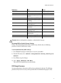
Rack Mount Requirements
You can rack mount your Effects or Editing system. Plan for sufficient space in your rack mount
chassis to install the following components:
• An HP xw9400 system
• An AJA OEM-2K breakout box
• A Miranda DVI-Ramp2
• A Stone Direct storage chassis (XR model)
• Additional Stone Direct expansion chassis (XE model), as required
The form factor units of these components are provided in the following table.
Component
Quantity
Form Factor
Required Rack Space
HP xw9400
1
5U
5U
AJA OEM-2K breakout box
1
1U
1U
Miranda DVI-Ramp2
1
1U
1U
Stone Direct storage chassis (XR)
1
2U
2U
Stone Direct expansion chassis (XE)
(each)
1
2U
2U
Avoiding Damage from Static Electricity
When installing any hardware equipment, take the following precautions to prevent damage to
sensitive components from static discharge:
• Make sure power is turned off on the component you are working on. It is a good idea to
unplug components until all other connections are configured.
• Always wear a grounded static wrist strap. Attach the strap’s alligator clip to any grounded
metal surface on the component’s chassis that you are working on. Place the wristband around
your wrist.
• Do not handle any components unnecessarily, particularly boards and cards that slide in and
out of PCI slots on their parent hardware components.
Grounding Audio Hardware Components
It is important to properly ground your audio components. Otherwise, you may have ground
loops, or humming in the system. To ensure audio components are properly grounded, use the
6
BIOS and Firmwares
XLR-3 cables shipped with your system. Using any other cables may cause humming in the
system.
Receiving Your Shipment
When you receive your shipment, check all the boxes for dents or other markings that may
indicate damage during transport. If you suspect a component is damaged, carefully inspect it
before setting up the system. If you receive a damaged component, call Customer Support.
Use the enclosed packing checklist to ensure that you received all of the parts.
BIOS and Firmwares
In most cases, hardware integration and application installation are done on delivery by an
authorized technician, so you should not have to verify or upgrade the BIOS or the different
firmwares. But, if you are upgrading your Effects or Editing application yourself, you must
follow the next procedures.
System BIOS
System configuration is done prior to delivery by an authorized technician. The procedures in
this section may not be necessary, and are provided here for informational purposes only.
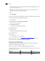
Verifying Your System BIOS
The system BIOS on your workstation must correspond to the certified version required by
your Effects or Editing application version. If the BIOS version on your system does not
correspond to the table below, you must update to the certified version.
Effect or Editing Product Version
Certified BIOS Version
2008
1.05
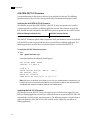
Updating Your System BIOS
The BIOS version installed on your system appears on the screen while booting the
workstation. The following procedure describes how to update a Linux workstation to the
certified BIOS version required by your Autodesk Effects or Editing application.
To update the BIOS on your workstation:
1. Load the DKU CD in the CD-ROM drive on the workstation.
2. Open a terminal.
3. Type:
cd /mnt/cdrom/Utils/BIOS
7
1 Introduction
Each platform supported by the version of your Effects or Editing application has its own
directory that contains an .iso file.
NOTE: For more information about updating the BIOS on your workstation, refer to the
README file also located in the platform’s directory.
4. Type:
cd <platform>
5. Burn the .iso file onto a CD-ROM and place it in the DVD-ROM drive on the workstation.
6. Reboot the workstation and press F10 to enter BIOS.
7. Select a language.
8. From the File menu, select Flash System ROM.
The Select a Drive menu appears.
9. Click Optical Drive.
The Select a Drive confirmation menu appears.
10. Press F10 to confirm.
11. Select the .bin file.
The Flash System ROM confirmation menu appears.
12. Press F10 to confirm.
13. Press any key.
System ROM Flash was successful appears.
14. Verify system BIOS settings. See “Checking Your System BIOS Settings” on page 8.
15. From the File menu, select Save Changes and Exit.
Checking Your System BIOS Settings
You do not normally need to adjust these settings. BIOS settings for the workstation are
provided here for informational purposes only.
To enter the system BIOS, you must press F10 while booting the workstation.
The following table lists the proper Autodesk certified BIOS settings. Items not listed are set to
their default factory settings.
BIOS Menu
Item
Storage
Boot Order
Value
Optical Drive
USB Device
8
BIOS and Firmwares
BIOS Menu
Item
Value
Boot Order, Hard Drive
Integrated SATA
Integrated IDE
Advanced
OS Power Management, ACPI S3 Disabled
Support
Chipset / Memory, ECC Support Enabled
I/O
Chipset / Memory, Memory
Scrubbing
Enable
Chipset / Memory, Memory
Node Interleave
Enable
Chipset / Memory, PCI Serr#
Generation
Enable
Chipset / Memory, Net
Watchdog Timer
Enable
Chipset / Memory, ACPI Bus
Segmentation
Disabled
Chipset / Memory, HPET
Enabled
Device Options, S5 Wake on LAN Disabled
WARNING: Before installing Red Hat 4 Update 3, validate the BIOS Settings.
Restoring BIOS to Default Factory Settings
If there is any doubt about whether items contain factory default values, the following
procedure restores default factory settings.
To restore default factory BIOS settings:
1. Press F10 while booting the workstation to enter the system BIOS.
2. From the File menu, select Default setup | Restore Factory Settings as
Default.
3. Press F10 to accept the changes.
4. Select Apply Defaults and Exit.
This restores the original factory system defaults.
DVI-Ramp Firmware
System configuration is done prior to delivery by an authorized technician. The following
procedures may not be necessary, and are provided here for informational purposes only.
9
1 Introduction
Verifying DVI-Ramp and DVI-Ramp2 Firmware
The firmware on your DVI-Ramp must correspond to the certified version required by your
Effects or Editing application version. Each firmware is itself associated to a DVI-Ramp version
and a hardware version. If the firmware on your DVI-Ramp does not match the hardware
version listed in the table below, you must update the firmware to the certified version.
Effects or Editing Product Version Hardware Version
2008 with
DVI-Ramp
Certified Firmware Version
3.20
3.70
DVI-Ramp
4.20
4.71
DVI-Ramp2
6.00
6.0506
6.0507
6.0508
The DVI-Ramp firmware update utilities required to check your firmware version and perform
the update are included with the DKU version associated with the release of your Effects or
Editing application. The following procedure describes how to verify the firmware version of
the DVI-Ramp.
To verify the firmware version of the DVI-Ramp:
1. With the DVI-Ramp connected to your workstation and powered up, log in as root and
open a terminal.
WARNING: If your DVI-Ramp unit is connected to the HP workstation using a USB-to-Serial
adapter, you must remove the adapter from the USB port, and connect the serial cable of the DVIRamp to the serial port of the workstation. This does not apply to DVI-Ramp2 units.
2. Insert the DKU CD in the CD-ROM drive.
3. Mount the CD-ROM by typing:
mount /mnt/cdrom
NOTE: If your workstation has multiple CD-ROM drives, the drive containing the DKU CD may
not be mapped as /mnt/cdrom. You can use any mapped CD-ROM drive for this procedure by
using the appropriate mount point for the CD-ROM drive in your workstation in these steps.
4. Go to the DVI_firmwareUpdate directory on the DKU CD. Type:
cd /mnt/cdrom/Utils/DVI_firmwareUpdate
5. Run the info command to scan the DVI-Ramp’s current firmware. Type:
./info
10
BIOS and Firmwares
The output is similar to the following example:
Versions:
Hardware = <Hardware Version>
Micro = <Firmware version>
Genlock = 3.21
DVI = 4.01
FrameBuffer = 4.05
SDI = 4.10
Where <Hardware Version> is the current version of the DVI-Ramp hardware, and
<Firmware version> is the firmware currently loaded in the DVI ramp. If the
firmware version does not match the hardware version listed in the table that precedes this
procedure, you must perform the firmware update procedure.
Updating the DVI-Ramp Firmware
The firmware on your DVI-Ramp must correspond to the certified version required by your
Effects or Editing application version. If you verified the firmware on your DVI-Ramp and it did
not match the certified version, you must update it. The following procedure describes how to
update the firmware version of the DVI-Ramp.
To update the DVI-Ramp firmware:
1. Go to the DVI_firmwareUpdate directory on the DKU CD. Type:
cd /mnt/cdrom/Utils/DVI_firmwareUpdate
2. From the DVI_firmwareUpdate directory, launch the DVI-Ramp upgrade utility by typing:
./updateDVI
The script checks the hardware version of the DVI-Ramp and then installs the firmware
update. The update should take between 5 and 10 minutes. You can monitor the progress of
the firmware update in the terminal.
The DVI-Ramp is rebooted several times during the firmware update. Any monitors
connected directly to the DVI-Ramp (such as the graphics monitor and/or a broadcast
monitor) will flash each time the DVI-Ramp is rebooted. This is normal and indicates that
the firmware is being updated.
3. Once the firmware update is complete, updated hardware information for your DVI-Ramp
appears in the terminal.
4. If you had to remove the USB-to-Serial adapter, reconnect the serial cable to the adapter,
then put the adapter back in the USB port. Restart the HP workstation.
11
1 Introduction
AJA OEM-2K PCI-X Firmware
System configuration is done prior to delivery by an authorized technician. The following
procedures may not be necessary, and are provided here for informational purposes only.
Verifying the AJA OEM-2K PCI-X Firmware
The firmware on your AJA OEM-2K PCI-X (AJA PCI-X) must correspond to the certified
version required by your Effects or Editing application version. If the firmware on your AJA
PCI-X board does not correspond to the table below, you must update it to the certified version.
Effect or Editing Product Version
Certified Firmware Version
2008
0x50
The AJA PCI-X firmware update utilities required to check your firmware version are included
with the DKU version associated with the release of your Effects or Editing application. The
following procedure describes how to verify the firmware version of the AJA PCI-X.
To verify the AJA PCI-X firmware version:
h Type:
cat /proc/driver/aja
An output similar to the following should appear:
AJA Driver Name: oem2k
Version: 4.1 Beta 9
Card #: 0
Board Version String: OEM 2K - Rev 0
PCI Version: 0x50
Board ID: 10196500
FPGA built on 2006/08/17 at 08:21:11
NOTE: If there is no aja file in /proc/driver, you are using an outdated driver or the driver is not
loaded and you must install the latest DKU for your workstation. Refer to the Autodesk Effects
and Editing 2008 Software Installation Guide for Linux Workstations.
Updating the AJA PCI-X Firmware
The firmware on your AJA PCI-X must correspond to the certified version required by your
Effects or Editing application version. If you verified the firmware on your AJA PCI-X and it did
not match the certified version, you must update it. The following procedure describes how to
update the firmware of the AJA PCI-X to the certified version required by your Effects or
Editing application.
12
BIOS and Firmwares
To update AJA PCI-X firmware:
1. Log in as root and open a terminal.
2. Insert the DKU CD in the CD-ROM drive.
3. Mount the CD-ROM by typing:
mount /mnt/cdrom
NOTE: If your workstation has multiple CD-ROM drives, the drive containing the DKU CD may
not be mapped as /mnt/cdrom. You can use any mapped CD-ROM drive for this procedure by
using the appropriate mount point for the CD-ROM drive in your workstation in these steps.
4. Go to the AJA_firmwareUpdate directory on the DKU CD. Type:
cd /mnt/cdrom/Utils/AJA_firmwareUpdate
5. Run the AJAfw_update utility to scan the AJA current firmware and, if required, update to
the latest firmware version. Type:
./AJAfw_update
The script checks the firmware of your AJA board, and one of the following events occurs:
• The script detects that the firmware and drivers need to be updated and prompts you to
start the update. In this case, continue to the next step of this procedure.
• The script indicates that the firmware is up-to-date and exits. In this case, you are finished;
go to step 7 of this procedure to eject the DKU CD.
NOTE: For more details about the AJA firmware procedures, consult the README file located in
the current directory.
6. Start the firmware update by typing Y and then pressing ENTER.
While the AJA board’s firmware and drivers are being updated, your workstation appears to
be frozen and your mouse and keyboard do not work. This is normal and indicates that the
firmware is being updated. Once the firmware update is complete, you are returned to the
terminal.
7. When you are returned to the terminal, return to the root directory and eject the DKU CD
from the CD-ROM drive by typing the following commands:
cd /
eject /mnt/cdrom
8. Shut down your Linux workstation by typing:
shutdown -g0
13
1 Introduction
If your workstation does not prompt you to power down, press the power button for 10
seconds to force a power down.
9. Disconnect the power cord.
10. Wait 10 seconds, reconnect the power cord, then restart your workstation normally.
Notation Conventions
A number of style conventions are used throughout this guide. These conventions and examples
of their use are shown as follows.
Convention
Example
Text that you enter in a command line or shell appears in
Courier bold. You must press the Enter key after each
command.
rpm -qa
Variable names appear in Courier, enclosed in angle brackets. <filename>
Variables that appear enclosed in square brackets are
optional.
[<filename>]
Feedback from the command line or shell appears in Courier. limit coredumpsize
Directory names, filenames, URLs, and command line utilities /usr/discreet
appear in italics.
Contacting Customer Support
You can contact Autodesk Media and Entertainment Customer Support at www.autodesk.com/
support. Refer to the following table for additional contact information.
14
Location:
Contact Information:
Within the Americas:
Hotline (North America): 1-800-925-6442
Direct dial: 415-507-5256 (Country code = 1)
Within Montreal: 514-954-7199
8 AM to 8 PM EST Monday to Friday, excluding holidays
[email protected]
Within Europe, Middle-East and
Africa:
Hotline (from London, UK): +44 207 851 8080
9 AM to 5:30 PM (local time)
Monday to Friday, excluding holidays
[email protected]
Within Asia Pacific:
(Excluding India, China,
Australia, New Zealand and
Japan)
Hotline (from Singapore): +65 6555 0399
9 AM to 6 PM (local time)
Monday to Friday, excluding holidays
[email protected]
Contacting Customer Support
Location:
Contact Information:
Within India:
Hotline (from Mumbai): +91 22 66952244
9:30 AM to 6:30 PM (local time)
Monday to Friday, excluding holidays
[email protected]
Within Japan:
Hotline (from Tokyo): 0120 107 290
Direct dial: +81 3 62211810
10 AM to 6 PM (local time)
Monday to Friday, excluding holidays
[email protected]
Within China:
Direct dial: +86 10 65056848
9 AM to 6 PM (local time)
Monday to Friday, excluding holidays
[email protected]
Within Australia and New
Zealand:
Hotline (within Australia to Melbourne): +1 300 368 355
Hotline (within New Zealand to Melbourne): 0800 555301
Direct dial: +61 3 9876 8355
8 AM to 6 PM AEST
Monday to Friday, excluding certain holidays
[email protected]
Customer support is also available through your Autodesk reseller. To find a reseller near you,
consult the reseller look-up database on the Autodesk Web site at www.autodesk.com/resellers.
15
1 Introduction
16
Connecting Peripherals
Summary
Peripherals Connection Diagram . . . . . . . . . . . . . . . . . . . . . . . . . . . . . . . . . . . . . . . . .
Connecting the Keyboard, Mouse, and Tablet . . . . . . . . . . . . . . . . . . . . . . . . . . . . .
Network Connections . . . . . . . . . . . . . . . . . . . . . . . . . . . . . . . . . . . . . . . . . . . . . . . . . . . .
Connecting Storage . . . . . . . . . . . . . . . . . . . . . . . . . . . . . . . . . . . . . . . . . . . . . . . . . . . . . .
Connecting Archive Storage . . . . . . . . . . . . . . . . . . . . . . . . . . . . . . . . . . . . . . . . . . . . . .
17
18
19
20
20
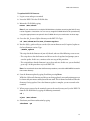
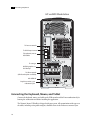
Peripherals Connection Diagram
You must connect all hardware peripheral devices before you boot your workstation. The
following diagram identifies the ports to which the peripherals connect on the HP xw9400
workstation.
All of the diagrams in this document contain a Gigabit Ethernet (GigE) network adapter located
in PCI slot four. Your workstation may be configured with an optional QuickSilver InfiniSERV
9000 PCIe-DDR adapter that replaces the GigE adapter. On the HP xw9400 workstation the PCI
slots are numbered one to seven from top to bottom.
For detailed information on video connections, refer to Chapter 3, “Setting Up Video
Hardware,” on page 23.
For detailed information on audio connections, refer to Chapter 4, “Setting Up Audio
Hardware,” on page 31.
17
2 Connecting Peripherals
HP xw9400 Workstation
To house network
To DVI-Ramp2 control
To keyboard, mouse,
USB tablet
To storage
NVIDIA graphics to
DVI-Ramp2
To Wire network
(Infiniband option available)
AJA OEM-2K
Graphics monitor sync
reference input
Connecting the Keyboard, Mouse, and Tablet
Connect the keyboard, mouse, and tablet to the USB extender and the Linux workstation before
booting the workstation and before installing the application.
The Wacom® Intuos USB tablet is shipped with your system. All customization with respect to
the tablet, including setting tablet margins, should be done in the Preferences menu of your
18
Network Connections
application. For help, see the description of Pointer preferences in the User’s Guide for your
application.
Network Connections
Consult the “Peripherals Connection Diagram” on page 17 as a reference for network interface
card (NIC) locations.
Connecting to Gigabit Ethernet (GigE) Networks
You must use the correct Gigabit Ethernet network card to connect your Linux workstation to
the Wire network. Otherwise, you may degrade the performance of your Wire network.
Do the following to maximize Wire network performance in your facility:
• Connect ports from the add-on network card to the switch used for your Wire network.
• Connect the house network to the on-board network port shown in “Peripherals Connection
Diagram” on page 17. Do not use any of the ports on the add-on network card for your house
network. If the house network is not connected to the on-board network port, consult your
system administrator to reconfigure it.
• Use high-quality Category 6 (Cat 6) network cables when connecting the Linux workstation
to your Wire network switch.
Connecting to the Infiniband (IB) Network
Your Linux workstation may be configured with an optional QuickSilver InfiniSERV 9000
PCIe-DDR series IB adapter. The IB network adapter resides in PCI slot four. On the HP
xw9400 workstation the PCI slots are numbered one to seven from top to bottom. Consult the
“Peripherals Connection Diagram” on page 17 as a reference for the optional IB network
adapter location.
You must use the correct port on the IB network adapter to connect your Linux workstation to
the IB Network.
19
2 Connecting Peripherals
To connect the workstation to IB network:
h Connect port 1 of the IB network adapter to the IB network. On the HP xw9400 workstation
Port 1 is the port on the right. For information on how to configure the IB adapter, refer to
the Stone and Wire Filesystem and Networking Guide.
Connecting Storage
You can connect your Linux workstation to two types of storage:
• One or more Stone Direct disk arrays that provide storage to individual workstations. Refer to
the Autodesk Stone Direct 2008 Configuration Guide for information on connecting disk arrays
to your workstation.
• A storage-area network (SAN), such as a CXFS volume. Refer to the SAN vendor
documentation for details on SAN configuration.
Consult the Autodesk Web site at www.autodesk.com/discreet-documentation for the latest
version of these guides.
WARNING: The 64-bit Linux operating system has a filesystem limit of 8 terabytes. When
configuring your storage, ensure each partition does not exceed 8 terabytes, and that inodes are
correctly configured. Refer to the Stone and Wire Filesystem and Networking Guide.
Connecting and Configuring the ATTO Fibre Channel Adapter
Your Linux workstation is configured with a 4-port ATTO Celerity FC-44ES fibre channel
adapter in PCI slot one. On the HP xw9400 workstation the PCI slots are numbered one to
seven from top to bottom. Consult the “Peripherals Connection Diagram” on page 17 as a
reference for the ATTO fibre channel adapter location.
Connecting Archive Storage
For data archiving, your Effects or Editing 2008 application supports the following devices:
• USB 2 and FireWire® (IEEE 1394) attached devices. They can be formatted as XFS, ext2, ext3,
or HFS (Mac®) file systems. NTFS is not supported.
• Fibre channel devices that use standard UNIX tape device calls.
The fibre channel devices that may be used are the ones for which the vendor confirms the
following:
• The device driver is compliant with standard UNIX tape device calls.
• The device is certified for use with the specific versions of your operating system and kernel,
Linux Red Hat Enterprise Workstation 4.0, Update 3.
20
Connecting Archive Storage
While Autodesk Media & Entertainment makes no certification statement about any device, the
following SCSI devices have been tested and found to be reliable when connected using an
ATTO Fibre Channel to SCSI Bridge 2390:
• Quantum LT03
• Quantum DLT8000
• Quantum DLT7000
• Sony™ AIT3 SDX-D700C
• Sony AIT2
Configuring the Archiving Device
The software initialization file (init.cfg) for your Effects or Editing 2008 application contains
examples of the use of the ClipMgtDevice Tape keywords. Use them to select a block size value
for your tape device, as well as to select a text label that identifies the device in the Archiving
module. Refer to the Configuration File Reference Guide for your operating system for additional
information.
You should also refer to the documentation from your archiving device vendor for guidelines
on the actual block size to use.
21
2 Connecting Peripherals
22
Setting Up Video Hardware
Summary
Video Hardware Components . . . . . . . . . . . . . . . . . . . . . . . . . . . . . . . . . . . . . . . . . . . .
Wiring Your Video Components . . . . . . . . . . . . . . . . . . . . . . . . . . . . . . . . . . . . . . . . . .
Standard VTR Control Cable . . . . . . . . . . . . . . . . . . . . . . . . . . . . . . . . . . . . . . . . . . . . . .
Setting Up VTR Emulation . . . . . . . . . . . . . . . . . . . . . . . . . . . . . . . . . . . . . . . . . . . . . . . .
23
24
26
26
Video Hardware Components
You use the video components to set up video I/O and a broadcast monitor. The only video
hardware you must provide are a sync generator, a VTR, and a HD/SDI broadcast monitor. The
following components are included in your hardware shipment.
AJA OEM-2K board and Breakout Box — The AJA OEM-2K board and breakout box
provides video I/O, audio, and VTR control. The AJA breakout box connects to the AJA OEM2K board and handles SD (NTSC, PAL), and HD at a depth of 8 and 10 bits.
NVIDIA Quadro FX 5500G graphics board — The NVIDIA® Quadro® FX 5500G is the
graphics board for 2K/DI configurations, and provides output to your computer and broadcast
monitor.
LCD graphics monitor — The LCD graphics monitor features a wide screen that makes a 16:9
aspect ratio possible for HD projects. With this monitor, the application runs at a maximum
resolution of 1920x1200.
Miranda DVI-Ramp2 — The DVI-Ramp2 connects the Linux workstation to two display
devices: a high-resolution computer monitor and a broadcast monitor. This allows the
application user interface to be displayed on a standard, non-interlaced, high-resolution
computer monitor, while the portion of the user interface containing video content (preview
window) is extracted and output on a broadcast video monitor. The DVI-Ramp2 can output
either a standard definition serial digital video signal or a high definition serial digital video
signal. It provides a real-time preview to both the graphics display and broadcast monitor.
23
3 Setting Up Video Hardware
Altinex® DA1804NT video distribution amplifier — The Altinex video distribution
amplifier can serve up to four video hardware devices from a single sync source/generator. It
serves the sync signal to the NVIDIA graphics board, the AJA OEM-2K board, and the Miranda
DVI-Ramp2.
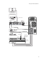
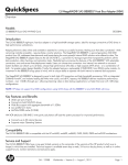
Wiring Your Video Components
Use this section to connect an HP xw9400 workstation equipped with an AJA OEM-2K board
and Miranda DVI-Ramp2 for video I/O.
Note the following about the wiring diagram:
• Do not use an SD (NTSC or PAL) sync generator for HD projects. Always use a tri-level sync
generator for HD projects. Using the wrong sync generator for a project may impact the
stability of your workstation.
• The sync source is connected to the Altinex video distribution amplifier. It is critical to
connect the Altinex distribution amplifier exactly as shown in the diagram to ensure the sync
works correctly.
• The VTR is connected to the SDI In A and SDI Out A ports of the AJA breakout box. You can
use the SDI In B and SDI Out B ports for dual link video I/O.
• VTR control is provided through the RS-422 port on the AJA breakout box.
24
Wiring Your Video Components
SD/HD SDI IN 2
SD/HD SDI IN 1
HD/SDI Monitor
(not included)
Graphics Monitor
VGA
VGA
DVI
DVI Active Cable
75 Ohm
Terminator
REF IN
1
SD/HD SDI OUT A
SD/HD SDI IN
Miranda
DVI Ramp2
2
I
SD/HD
Ref
2
1
SD/HD SDI OUT B
ETH 10/100
USB port
RS-232/GPI
0
DVI-D IN A
DVI-D OUT A
DVI-D IN B
USB
DVI-D OUT B
S y nG
c en
S y nG
c en
Altinex Video
Distribution
Amplifier
12V
2A
DVI (DL.CAB-DVI-DSL-2 )
Standard BNC cable
SDI In / Out
4:4:4
from house sync generation
(Trilevel/NTSC/PAL not included)
to RS-422 VTR
machine control
SDI In / Out
AES/EBU
Audio
Ch. 1/2 In
Ch. 3/4 In
Ch. 5/6 In
Ch. 7/8 In
Ch. 1/2 Out
Ch. 3/4 Out
Ch. 5/6 Out
AJA BOB (Front)
In
Out
In
Out
Ch. 1/2
Ch. 3/4
In
Out
Ch. 5/6
Video MonitorOut
In
Out
Ch. 7/8
SDI 1/A
Y/G/CVBS
SDI 2/B
Ref Loop
Pb/B/Y
Pr/R/C
RS-422
Ch.1(L)
Ch.2(R)
75 Ohm
Terminator
AJA BOB (Back)
A Jwww.aja.c
A om
Ch. 7/8 Out
K3-Box
102053
Connect to Host
J1
In 1/A
In 2/B
Out 1/A
Out 2/B
25
3 Setting Up Video Hardware
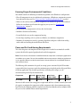
Standard VTR Control Cable
The following diagram depicts the RS-422 control cable pinouts for the standard VTR control
cable.
Standard VTR Control Cable:
Linux/AJA Controlling VTR (Normal Video I/O Control Cable)
VTR
Linux/AJA
1
6
2
7
3
8
4
9
5
1
6
2
7
3
8
4
9
5
OEM-2K: MALE DB9
OEM-LH: FEMALE DB9
MALE DB9
2 - RX 7 - RX +
3 - TX 8 - TX+
WHT
2 - TX -
BLK
7 - TX +
RED
3 - RX -
BLK
8 - RX+
GND
4 - GND (SHIELD)
PAIR 1
PAIR 2
4 - GND (SHIELD)
Setting Up VTR Emulation
You can configure your Editing application to emulate a VTR for both input and output in real
time. You control the emulator from the application or device that sees the Editing application
as a VTR.
The following procedure describes how to configure the hardware for VTR emulation. Consult
the “VTR Emulation” chapter in the User’s Guide for your Editing application for more
information.
26
Setting Up VTR Emulation
To configure hardware for VTR emulation:
1. Connect the video I/O cables between the devices involved in the VTR emulation process
(out-to-in/in-to-out). Make sure the connections support the video standard you want to
work with.
If you intend to use the emulator as a Player, it is recommended that you connect one black
or colour bar SDI signal to the input of the system serving as the VTR emulator. This ensures
the Player is stable and correctly synced.
NOTE: VTR emulation requires an Editing workstation with a video board. The Video keyword
for the corresponding device must be uncommented in the software initialisation
configuration file. See the description of the Video keyword in the Configuration File Reference
Guide for Linux Workstations for your release.
2. Connect the audio I/O cables between the devices involved in the VTR emulation process
(out-to-in/in-to-out).
If you intend to use the emulator as a Player, it is recommended that you connect an external
AES signal such as a tone to the input of the system serving as the VTR emulator. This
ensures the Player is stable and correctly synced.
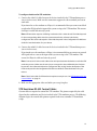
NOTE: Connect an RS-422 control cable to the serial ports between the devices used in the VTR
emulation process. Make sure the serial ports correspond to those defined by the Emulator
keywords in the software initialisation configuration file, init.cfg. See the description of the
Emulator keyword in the Configuration File Reference Guide for Linux Workstations for your
release.
NOTE: The RS-422 cables for VTR emulation require custom pinouts. See “VTR Emulation RS-422
Control Cables” on page 27.
3. Make sure the appropriate video and audio sync setup is in place.
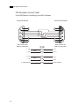
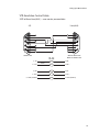
VTR Emulation RS-422 Control Cables
Custom cables are required to control the VTR emulator. The pinouts required by the cable
depend on the workstation and device involved in the VTR emulation process. The following
diagrams depict the control cable pinouts required for the most common VTR emulation
setups.
27
3 Setting Up Video Hardware
VTR-Emulation Control Cable:
Linux(AJA) Master Controlling Linux(AJA) Emulator
Linux(AJA) Master
Linux(AJA) Emulator
1
6
2
7
3
8
4
9
5
1
6
2
7
3
8
4
9
5
OEM-2K: MALE DB9
OEM-LH: FEMALE DB9
OEM-2K: MALE DB9
OEM-LH: FEMALE DB9
2 - RX 7 - RX +
8 - TX 3 - TX+
4 - GND (SHIELD)
28
WHT
8 - TX -
BLK
3 - TX +
RED
2 - RX -
BLK
7 - RX+
GND
4 - GND (SHIELD)
PAIR 1
PAIR 2
Setting Up VTR Emulation
VTR-Emulation Control Cable:
SGI® to/from Linux(AJA) — one master, one emulator
SGI
Linux(AJA)
1
6
2
7
3
8
4
9
5
1
6
2
7
3
8
4
9
5
OEM-2K: MALE DB9
OEM-LH: FEMALE DB9
FEMALE DB9
3 - TX 4 - TX +
2 - RX 6 - RX +
5 - GND (SHIELD)
WHT
2 - RX -
BLK
7 - RX +
RED
8 - TX -
BLK
3 - TX +
GND
1 - GND (SHIELD)
PAIR 1
PAIR 2
29
3 Setting Up Video Hardware
VTR-Emulation Control Cable:
3rd-Party Device Master Controlling Linux(AJA) Emulator
3rd-Party Device Master
Linux(AJA) Emulator
1
6
2
7
3
8
4
9
5
1
6
2
7
3
8
4
9
5
OEM-2K: MALE DB9
OEM-LH: FEMALE DB9
MALE DB9
2 - RX 7 - RX +
8 - TX 3 - TX+
4 - GND (SHIELD)
30
WHT
8 - TX -
BLK
3 - TX +
RED
2 - RX -
BLK
7 - RX+
GND
4 - GND (SHIELD)
PAIR 1
PAIR2
Setting Up Audio Hardware
Summary
About Audio . . . . . . . . . . . . . . . . . . . . . . . . . . . . . . . . . . . . . . . . . . . . . . . . . . . . . . . . . . . . .
Audio Wiring Workflow . . . . . . . . . . . . . . . . . . . . . . . . . . . . . . . . . . . . . . . . . . . . . . . . . .
Audio Hardware Components . . . . . . . . . . . . . . . . . . . . . . . . . . . . . . . . . . . . . . . . . . . .
Understanding Remote vs. Local Control of the Lucid Converter . . . . . . . . . . . .
Audio Wiring . . . . . . . . . . . . . . . . . . . . . . . . . . . . . . . . . . . . . . . . . . . . . . . . . . . . . . . . . . . .
Configuring the Lucid ADA 88192 Converter . . . . . . . . . . . . . . . . . . . . . . . . . . . . . .
Audio Keywords in the Software Initialisation Configuration File . . . . . . . . . . .
31
31
32
32
32
34
36
About Audio
Your application uses the Discreet® Native Audio subsystem. Discreet Native Audio offers 8
audio input and 8 audio output channels. They all use 24-bit audio resolution.
Audio Wiring Workflow
The following procedure provides the general workflow for setting up the audio subsystem of
your Effects or Editing application.
To wire the audio subsystem:
1. Ensure that all of your workstation peripherals and video hardware components are
properly connected. If necessary, refer to Chapter 2, “Connecting Peripherals,” on page 17
and Chapter 3, “Setting Up Video Hardware,” on page 23.
2. Verify that you have all the required audio hardware components. See “Audio Hardware
Components” on page 32.
3. Determine whether you want to control the Lucid converter remotely or locally. This affects
the way you wire the audio hardware. See “Understanding Remote vs. Local Control of the
Lucid Converter” on page 32.
31
4 Setting Up Audio Hardware
4. Connect your audio hardware devices. To avoid system instability, make sure you connect
your audio hardware as illustrated for your configuration. See “Audio Wiring” on page 32.
5. Configure the Lucid converter for remote or local control. See “Configuring the Lucid ADA
88192 Converter” on page 34.
6. Set the appropriate keywords in the software initialisation file. See “Audio Keywords in the
Software Initialisation Configuration File” on page 36.
Audio Hardware Components
Discreet Native Audio uses the following hardware components, shipped with your system.
Lucid Converter ADA 88192 — Converts signals between the Linux workstation and all
digital or analog audio I/O devices.
AJA Balanced Audio breakout box and AJA OEM-2K board — The Balanced Audio
breakout box is the audio component of the AJA Breakout Box. It provides connections for
audio I/O. This breakout box connects to the AJA OEM-2K board on your workstation. The
OEM-2K board provides real-time input and output of uncompressed SD and HD video signals
as well as audio data at 24-bit resolution. The OEM-2K board handles balanced AES/EBU audio
signals from the Balanced Audio breakout box.
Understanding Remote vs. Local Control of the Lucid Converter
You can control the converter either remotely or locally. Remote control of the converter means
that you adjust converter settings through the audio preferences of the application. If you want
to control the converter remotely, you must connect the converter to the serial port of the HP
xw9400 workstation. Local control means you adjust converter settings manually, using the
controls on the front of the converter. Controlling the converter remotely is the recommended
method as it does not require physical access to the converter to change settings.
Whether you control the converter remotely or locally, you should take any necessary
precautions to prevent inadvertent adjustments to settings via the controls on the front of the
converter. For example, if the converter is one of several in a machine room, you might label
each with the name of the computer to which it is connected, along with whether control is local
or remote.
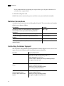
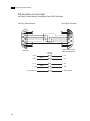
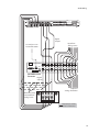
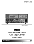
Audio Wiring
To connect the Discreet Native Audio hardware components to the AJA breakout box, refer to
the following diagram.
32
Audio Wiring
AJA
AES/EBU
Audio
Ch. 1/2 In
Ch. 3/4 In
Ch. 5/6 In
Ch. 7/8 In
Ch. 1/2 Out
Ch. 3/4 Out
Ch. 5/6 Out
Ch. 1/2
Ch. 7/8 Out
In
Out
In
Out
Ch. 3/4
In
Out
Ch. 5/6
Video Monitor Out
In
Out
Ch. 7/8
SDI 1/A
Y/G/CVBS
SDI 2/B
Pb/B/Y
RS-422
Pr/R/C
Ref Loop
Ch.1(L)
Ch.2(R)
AJA BOB (Front)
Digital
outputs
Input from
analog source
to serial port 1 on
Linux workstation
RS-232
ADAT OUT 1-8
WORD CLOCK
INPUT
ADAT IN 1-8
OUTPUT
Analog Inputs
AES/EBU Digital Inputs
88192 A/D D/A CONVERTER
7-8
7-8
5-6
3-4
AES/EBU Digital Outputs
5-6
3-4
1-2
8
7
6
1-2
8
7
6
5
4
Analog Outputs
5
4
3
2
1
3
2
1
Lucid ADA 88192
Converter
Digital
outputs
Output to
analog destination
Alternative setup
converted from
analog source
IN
IN
IN
IN
OUT OUT OUT OUT
VTR
Required for remote
control of converter
33
4 Setting Up Audio Hardware
Configuring the Lucid ADA 88192 Converter
You must manually configure the Lucid converter for either remote or local control. This section
describes how to use the controls on the front of the converter to adjust settings, and lists the
proper settings for remote control and for local control.
Adjusting Lucid ADA 88192 Converter Settings
You configure the converter through a series of setup menus that appear in the display on the
front of the converter. Use the encoder dial and button immediately to the right of the display to
navigate these menus and adjust settings.
The top level setup menu contains the following menu items: ADAT, AES, Analog, Meter, Route,
Sync, and System. Each of these menu items takes you into a submenu, from which you can
select and adjust settings.
The procedures below provide basic information on navigating and adjusting settings. If you
require additional information, refer to the Lucid ADA 88192 manual included with your
shipment.
To navigate menus and adjust settings:
h Use the encoder dial and the button as follows.
To:
Do this:
Select a menu option Rotate the dial to highlight the option, then press the dial to select
that option. If the option you select has choices (as for example in
the Route menu), rotate the dial again to move through the choices,
and press the dial to select an option.
Back up one level in
the menu tree
Press the button.
Navigate to the top
level setup menu
Press the button. Repeat until you are in the top level setup menu.
To reset all settings to their factory defaults:
1. In the top level setup menu, select System, then select Miscellany.
2. In the Miscellany menu, select Defaults: RESET.
All settings are reset to their factory defaults.
NOTE: The factory default for the items in the AES setup menu is SRC ON. Both local and remote
control require these items to be set to SRC OFF. If you reset to defaults, be sure to manually set
these items back to OFF (you cannot adjust these settings remotely).
34
Configuring the Lucid ADA 88192 Converter
Lucid ADA 88192 Converter Settings for Remote Control
You must configure the following settings to control the converter remotely. Any setting not
listed here either has no effect with the application or can be set through the audio preferences
of the application.
Menu
Menu Item
ADAT
ADAT INs: SRC ON
ADAT INs: SMUX OFF
Comment
AES
AES IN1+2: SRC OFF
AES IN3+4: SRC OFF
AES IN5+6: SRC OFF
AES IN7+8: SRC OFF
Analog
Analog INs: SoftClip
IN1+2: SoftClip OFF
IN3+4: SoftClip OFF
IN5+6: SoftClip OFF
IN7+8: SoftClip OFF
Meter
Clip Detect: 3
3 is the recommended setting
System
Miscellany
Route Unit: 8
8 is the recommended setting
Lucid ADA 88192 Converter Settings for Local Control
You must configure the following settings to control the converter locally. Any setting not listed
here either has no effect with the application or can be set to any of the values available for it.
Menu
Menu Item
ADAT
ADAT INs: SRC ON
ADAT INs: SMUX OFF
AES
AES IN1+2: SRC OFF
AES IN3+4: SRC OFF
AES IN5+6: SRC OFF
AES IN7+8: SRC OFF
Analog
Analog INs: SoftClip
IN1+2: SoftClip ON
IN3+4: SoftClip ON
IN5+6: SoftClip ON
IN7+8: SoftClip ON
Analog
Analog INs: Gain
set each input channel to a
value in the range
-95.5 to +31.5 dB
Analog
Analog OUTs: Level
set either -10 or +4 for each
output channel
Meter
Clip Detect: 3
Comment
3 is the recommended setting
35
4 Setting Up Audio Hardware
Menu
Menu Item
Comment
Route
For analog audio:
AES INs --> ADAT OUTs
Analog INs --> AES OUTs
AES INs --> Analog OUTs
If these options do not appear, verify
that Route Unit (in the System,
Miscellany menu) is set to 8.
For digital audio:
AES INs --> ADAT OUTs
AES INs --> AES OUTs
AES INs --> ANALOG OUT
Sync
Internal OFF
External AES 1+2
System
Miscellany
Route Unit: 8
External AES 1+2 is the recommended
setting.
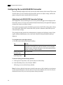
Audio Keywords in the Software Initialisation Configuration File
There are two keywords in the software initialisation file (by default, init.cfg) that must be
uncommented and set to the correct values to ensure Discreet Native Audio works properly. The
first, Audiodevice, enables Discreet Native Audio. The second, MidiDevice, determines
whether control of the Lucid converter is remote or local.
Keyword:
Setting:
Audiodevice
AJA
MidiDevice
If you are using local control of the converter, comment out this
keyword.
If you are using remote control of the converter, uncomment the
keyword, set the serial port parameter to /dev/ttyS1 and leave all
other parameters set to their default value.
For additional information on these keywords and help setting them, see the Configuration File
Reference Guide for Linux Workstations.
36
index
Index
A
M
air conditioning, requirements 5
audio
Discreet Native Audio 31
hardware components 32
keywords in software initialisation file 36
wiring workflow 31
memory requirements 4
mouse, connecting 18
B
broadcast monitor, wiring 24
C
configuring, Lucid ADA 88192 converter 34
D
Discreet Native Audio 31
documentation, set of guides 2
N
notation conventions 14
P
power, requirements 5
S
software initialisation file, audio keywords 36
T
tablet, connecting 18
V
emulation, setting up VTR 26
video hardware components 23
video I/O, wiring 24
VTR emulation, setting up 26
H
W
E
hardware configuration guidelines 3
I
initialisation file keywords, audio 36
Wire network, connecting to 19
wiring video I/O and broadcast monitor 24
workflow, audio wiring 31
workflow, hardware setup and software installation 3, 7
K
keyboard, connecting 18
L
Lucid ADA 88192 converter, configuring 34
37
Index
38