1
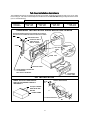
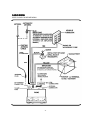
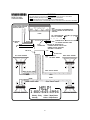
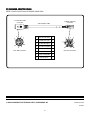
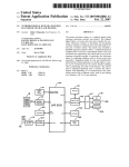
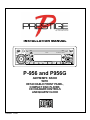
INSTALLATION MANUAL
P-956G
MULTI
JOG
ILL
MODE
1
PAU
2 SCN
3
RPT
CD-R/RW PLAYBACK
4
SHF
5
CD-
6
CD+
P-956 and P956G
AM/FM/MPX RADIO
WITH
DETACHABLE FRONT PANEL,
COMPACT DISC PLAYER,
CD CHANGER CONTROLS
AND QUARTZ CLOCK
Released: 7-14-03
INSTALLATION INSTRUCTIONS
This unit is designed for installation in cars, trucks, and vans with an existing radio opening. In many cases, a special installation
kit will be required to mount the radio to the dashboard. These kits are available at electronics supply stores and car stereo
specialist shops. Always check the kit application before purchasing to make sure the kit works with your vehicle. If you need a
kit but cannot find it available, call our toll-free “HELP” line at 1-800-645-4994.
UNIVERSAL INSTALLATION PROCEDURE USING MOUNTING SLEEVE
1. Remove the detachable front panel if it is attached to the chassis by pushing the “Release” button. Slide the mounting sleeve
off of the chassis. If it is locked into position, use the removal tools (supplied) to disengage it.
2. Check the dashboard opening size by sliding the mounting sleeve into it. If the opening is not large enough, carefully cut or
file as necessary until the sleeve easily slides into the opening. Do not force the sleeve into the opening or cause it to bend
or bow. Check that there will be sufficient space behind the dashboard for the radio chassis.
3. Locate the series of bend tabs along the top, bottom, and sides of the mounting sleeve. With the sleeve fully inserted into the
dashboard opening, bend as many of the tabs outward as necessary so that the sleeve is firmly secured to the dashboard.
4. Place the radio in front of the dashboard opening so that the wiring can be brought through the mounting sleeve. Follow the
wiring diagram carefully and make certain all connections of the wiring harness are secure and insulated with wire nuts or
electrical tape to insure proper operation of the unit. After completing the wiring connections, attach the front panel and turn
the unit on to confirm operation (ignition switch must be “on”). If unit does not operate, re-check all wiring until problem is
corrected. Once proper operation is achieved, turn off the ignition switch and proceed with final mounting of the chassis.
5. Carefully slide the radio into the mounting sleeve making sure it is right-side-up until it is fully seated and the spring clips lock
it into place.
6. Attach one end of the perforated support strap (supplied) to the screw stud on the rear of the chassis using the hex nut provided.
Fasten the other end of the perforated strap to a secure part of the dashboard either above or below the radio using the screw
and hex nut provided. Bend the strap to position it as necessary.
CAUTION: The rear of the radio must be supported with the strap to prevent damage to the dashboard from the weight of the
radio or improper operation due to vibration.
7. Re-attach the front panel to the chassis and test radio operation by referring to the Operating Instructions for the unit.
INSTALLATION USING KITS
1. If your vehicle requires the use of an installation kit to mount this radio, follow the instructions included with the installation kit
to attach the radio to the mounting plate supplied with the kit.
2. Wire and test the radio as described in Step 4 of the installation procedure.
3. Install the radio/mounting plate assembly to the sub-dashboard according to the instructions of the installation kit.
4. Attach the support strap to the radio and dashboard as described in Step 6 above.
5. Replace the dashboard trim panel.
ISO INSTALLATION PROCEDURE
This unit has threaded holes in the chassis side panels which may be used with the original factory mounting brackets of some Toyota,
Nissan, Mitsubishi, Isuzu, Hyundai and Honda vehicles to mount the radio to the dashboard. Please consult with your local car stereo
specialist shop for assistance on this type of installation.
1. Remove the existing factory radio from its dashboard or center console mounting. Save all hardware and brackets as they will
be used to mount the new radio.
2. Carefully unsnap the plastic frame from the front of the new radio chassis. Remove and discard the frame.
3. Remove the factory mounting brackets and hardware from the existing radio and attach them to the new radio.
CAUTION : DO NOT EXCEED M5 X 8 MM MAXIMUM SCREW SIZE.
LONGER SCREWS MAY TOUCH AND DAMAGE COMPONENTS INSIDE THE CHASSIS.
4. Wire the new radio to the vehicle as per step 4 of the Universal Installation Procedure.
5. Mount the new radio assembly to the dashboard or center console using the reverse procedure of step 1.
-2-
Toll-Fr
ion As
sis
oll-Free e Ins
Instt allat
allation
Assis
sistt anc
ancee
The installation and wiring connections for this unit are so simple, we doubt you'll need our help, but, if you do, we're
here to help you. Just call our toll-free telephone assistance line at 1-800-645-4994 during the days and hours shown
(U.S.A. and Canada only).
TIME ZONE
EASTERN
CENTRAL
PACIFIC
MOUNTAIN
DAY
MON.-FRI.
SATURDAY
5:30AM - 4PM
6AM - 2PM
6:30AM - 5PM
7AM - 3PM
8:30AM - 7PM
9AM - 5PM
7:30AM - 6PM
8AM - 4PM
UNIVERSAL INSTALLATION USING MOUNTING SLEEVE
EXISTING DASH OPENING (FILE EDGES TO FIT IF NECESSARY-DO NOT OVERFILE)
NOTE: IF DASH IS SOLID, USE MOUNTING SLEEVE AS A TEMPLATE & CUT OPENING
NUT
PERFORATED STRAP
FASTEN THIS END TO
SCREW STUD ON
REAR OF CHASSIS
BEND TOP TABS
UPWARD
BEND BOTTOM TABS
DOWNWARD
SCREW
RADIO
SCREW STUD
REMOVAL
TOOLS
MOUNTING SLEEVE
FASTEN THIS END TO SECURE PART
OF DASHBOARD.
DRILL HOLE IF NECESSARY.
DETACHABLE
FRONT PANEL
ISO INSTALLATION
REMOVE THE PLASTIC FRAME FROM THE
FRONT OF THE CHASSIS BY CAREFULLY
UNSNAPPING IT.
TYPICAL INSTALLATION
MAX. SIZE
M5 x 8
Unsnap AT 2 PLACES
EACH ON TOP AND
BOTTOM
PLASTIC FRAME
FACTORY MOUNTING BRACKETS
-3-
R A DIO WIRING
REFER TO PAGE 5 FOR SPEAKER WIRING
PANEL
ILLUMINATION
PINK
-4-
SPE
A K ER WIRING
SPEA
WARNING!
l
l
l
l
REFER TO PAGE 4
FOR RADIO WIRING
THE AMPLIFIERS IN THIS RADIO ARE ONLY DESIGNED FOR USE WITH 4 SPEAKERS.
NEVER COMBINE (BRIDGE) OUTPUTS FOR USE WITH 2 SPEAKERS.
NEVER GROUND NEGATIVE SPEAKER LEADS TO CHASSIS GROUND.
FAILURE TO WIRE EXACTLY AS SHOWN BELOW MAY CAUSE ELECTRICAL DAMAGE TO THE RADIO.
RCA JACKS LINE OUT FOR USE WITH
OPTIONAL EXTERNAL AMPLIFIERS
RED = RIGHT, WHITE = LEFT
NOTE:
CALL 1-800-645-4994 FOR RECOMMENDATIONS
OF MODEL CHANGERS THAT WILL WORK WITH
YOUR RADIO.
RADIO
DIN CABLE (SUPPLIED
WITH CD CHANGER).
TELEPHONE
MUTE
GRAY
LOW
HI
PINK
OPTIONAL CD CHANGER
6
COMPA CT
8-PIN DIN SOCKET FOR CONNECTION TO
CD CHANGER ADAPTER CABLE
BLACK
ISO-TO-8 PIN DIN SOCKET CD
CHANGER ADAPTER CABLE, PART
NUMBER P956CDC (SUPPLIED)
SEE PAGE 6 FOR DETAILS
8-PIN
CONNECTORS
8-PIN PLUG
8-PIN PLUG
LEFT FRONT SPEAKER
SEE PAGE 4
FOR RADIO WIRING
RIGHT FRONT SPEAKER
GRAY w/BLACK STRIPE
WHITE w/BLACK STRIPE
WHITE
GRAY
VIOLET
GREEN
GREEN w/BLACK STRIPE
VIOLET w/BLACK STRIPE
HELP!
LEFT REAR SPEAKER
1-800-645-4994
Monday - Friday
Saturday
8:30am - 7:00pm Eastern
9:00am - 5:00pm Eastern
-5-
RIGHT REAR SPEAKER
CD CH
A NGER A
DA
PTER CABLE
CHA
ADA
DAPTER
REFER TO PAGE 5 FOR OPTIONAL CD CHANGER CONNECTIONS
To CDC DIN Cable
Connector
To Radio CDC ISO
Connector
8-Pin Adapter Cable
2
3
1
4
8
5
6
7
8-Pin DIN Connector
1
CD Left Input (Wht)
1
2
+12 Volts Acc (Yel)
2
3
CD Data Bus (Brn)
3
4
CD Audio Grd (Shld)
4
5
Data Bus Grd (Shld)
5
6
CD Right Input (Red) 6
7
Control Voltage (Blk)
7
8
CDC On (Grn)
8
1
3
4
5
6
© 2003 AUDIOVOX ELECTRONICS CORP., HAUPPAUGE, NY
2
7
8
8-Pin ISO Connector
Printed in China
128-6839
-6-