1
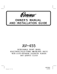
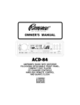
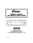
Installation Instructions for
Detachable Face Stereo Systems
CALL TOLL-FREE FOR ANSWERS TO INSTALLATION PROBLEMS
Continental U.S. : 1 - 800 - 645 - 4994
Monday - Friday : 9:00 AM - 7:00 PM Eastern Time
Saturday : 9:00 AM - 5:00 PM Eastern Time
IMPORTANT - RETAIN THIS DOCUMENT FOR FUTURE REFERENCE.
Consignes d’Installation des Systèmes Stéréo
avec Panneau Avant Amovible
APPELEZ LE NUMERO VERT POUR TOUTE QUESTION CONCERNANT L’INSTALLATION
Territoire Continental Des E.U. : 1 - 800 - 645 - 4994
Lundi au Vendredi : 9 H - 19 H Heure de la Côte Est
Samedi : 9 H - 17 H Heure de la Côte Est
IMPORTANT - CONSERVER CE DOCUMENT POUR TOUTE REFERENCE ULTERIEURE.
Instrucciones para la Instalación
de Sistemas Estereofónicos
con Panel Delantero Desmontable
LLAME SIN CARGO PARA FORMULAR PREGUNTAS SOBRE PROBLEMAS DE INSTALACION
Territorio Continental De EE.UU. : 1 - 800 - 645 - 4994
Lunes a Viernes : 9:00 AM - 7:00 PM Zona Horaria del Este
Sabados : 9:00 AM - 5:00 PM Zona Horaria del Este
IMPORTANTE - GUARDE ESTAS INSTRUCCIONES PARA CONSULTARLAS EN EL FUTURO.
© 2000 Audiovox Corporation, 150 Marcus Blvd., Hauppauge, N.Y. 11788
128-5726 (P-942)
INSTALLATION INSTRUCTIONS
UNIVERSAL INSTALLATION PROCEDURE USING MOUNTING SLEEVE
This unit is designed to fit into a standard DIN dashboard opening of 182 x 52 mm, common in many cars, trucks and vans. your car
does not have an existing opening of this size, it will be necessary to cut or file an opening to these dimensions. The rear side (without
the lip) of the mounting sleeve may be used as a template to cut the required opening.
In some cases, a special installation or adaptor kit may be required to properly mount the unit. These kits are available at electronics
stores and car stereo specialist shops. Always check the application before purchasing to be certain that it works with your vehicle.
For assistance or answers to installation problems, call Audiovox toll-free at 1-800-645-4994 (Continental U.S. only, 9:00 AM-7:00
PM Eastern Time Monday-Friday, 9:00 AM-5:00 PM Saturday, Holidays excluded), or consult with your local car stereo specialist shop.
1. Remove the detachable front panel if it is attached to the chassis by pushing the “Release” button. Slide the mounting sleeve
off of the chassis. If it is locked into position, use the removal tools (supplied) to disengage it.
2. Check the dashboard opening size by sliding the mounting sleeve into it. If the opening is not large enough, carefully cut or file
as necessary until the sleeve easily slides into the opening. Do not force the sleeve into the opening or cause it to bend or bow.
3. Check that there will be sufficient space behind the dashboard for the radio chassis.
4. In most installations, it is more convenient to complete the wiring before mounting the radio in the dashboard.
Follow the wiring diagram carefully and make certain all connections of the wiring harness are secure and insulated with wire nuts
or electrical tape to insure proper operation of the unit. After completing the wiring connections, plug the 9-pin and 4-pin connectors
into the mating sockets on the rear of the chassis, attach the front panel, and turn the unit on to confirm operation (ignition switch must
be “on”). If unit does not operate, re-check all wiring until problem is corrected. Once proper operation is achieved, turn off the
ignition switch, and proceed with final mounting of the chassis.
5. Carefully slide the radio into the mounting sleeve making sure it is right-side-up until it is fully seated and the spring clips lock
it into place.
6. Locate the series of bend tabs along the top, bottom, and sides of the mounting sleeve. With the sleeve fully inserted into the
dashboard opening, bend as many of the tabs outward as necessary so that the sleeve is firmly secured to the dashboard.
7. Thread and tighten the supplied screw stud to the mating hole on the rear of the chassis. Place the radio in front of the dashboard
opening so that the wiring (9-pin and 4-pin connectors, antenna lead, RCA leads if used, etc.) can be brought through the mounting
sleeve and plugged into the respective sockets on the rear of the chassis.
8. Carefully slide the radio into the mounting sleeve making sure it is right-side-up until it is fully seated and the spring clips lock
it into place.
9. Attach one end of the perforated support strap (supplied) to the screw stud using the hex nut provided. Fasten the other end of
the perforated strap to a secure part of the dashboard either above or below the radio using the screw and hex nut provided. Bend
the strap to position it as necessary.
CAUTION: The rear of the radio must be supported with the strap to prevent damage to the dashboard from the weight
of the radio or improper operation due to vibration.
10. Re-attach the front panel to the chassis and test radio operation by referring to the Operating Instructions for the unit.
REMOVING THE RADIO FROM MOUNTING SLEEVE INSTALLATIONS
1. Should it be necessary to remove the radio for servicing or other reasons, first remove the detachable front panel and trim ring..
2. Remove the rear support strap by taking off the hex nut securing it to the screw stud on the rear of the chassis.
3. Use the removal tools (supplied) to disengage the side spring clips and pull the radio out of the mounting sleeve.
INSTALLATION USING KITS
1. If your vehicle requires the use of an installation kit to mount this radio, follow the instructions included with the installation kit to
attach the radio to the mounting plate supplied with the kit.
2. Wire and test the radio as described in Step 4, Universal Installation procedure.
3. Install the radio/mounting plate assembly to the sub-dashboard according to the instructions of the installation kit.
4. Attach the support strap to the radio and dashboard as described in Step 6, Universal Installation procedure.
5. Replace the dashboard trim panel.
ISO INSTALLATION PROCEDURE
This unit has threaded holes in the chassis side panels which may be used with the original factory mounting brackets of some Toyota,
Nissan, Mitsubishi, Isuzu, Hyundai and Honda vehicles to mount the radio to the dashboard. Please consult with your local car stereo
specialist shop for assistance on this type of installation.
1. Remove the existing factory radio from its dashboard or center console mounting. Save all hardware and brackets as they will
be used to mount the new radio.
2. Carefully un-snap the plastic frame from the front of the new radio chassis. Remove and discard the frame.
3. Remove the factory mounting brackets and hardware from the existing radio and attach them to the new radio.
CAUTION: DO NOT EXCEED M5 X 8 MM MAXIMUM SCREW SIZE. LONGER SCREWS MAY TOUCH AND DAMAGE
COMPONENTS INSIDE THE CHASSIS. DEPENDING ON YOUR VEHICLE, YOU MAY BE REQUIRED
TO USE M5 X 8 MM OR M4 X 7 MM SCREWS. BOTH SIZES ARE PROVIDED FOR THE INSTALLATION.
4. Wire the new radio to the vehicle as per Step 4, Universal Installation procedure.
5. Mount the new radio assembly to the dashboard or center console using the reverse procedure of step 1 above.
-1-
UNIVERSAL INSTALLATION USING MOUNTING SLEEVE
EXISTING DASH OPENING
FILE EDGES TO FIT IF NECESSARY - DO NOT OVERFILE
NOTE: IF DASH IS SOLID, USE REAR SIDE (WITHOUT THE LIP) OF
MOUNTING SLEEVE AS A TEMPLATE & CUT OPENING
BEND TOP TABS
UPWARD
NUT (5MM)
PERFORATED STRAP
FASTEN THIS END TO
SCREW STUD ON
REAR OF CHASSIS
BEND BOTTOM TABS
DOWNWARD
SCREW (5MM)
RADIO
SCREW STUD
NUT (5MM)
MOUNTING SLEEVE
FASTEN THIS END TO SECURE PART OF DASHBOARD.
REMOVAL TOOLS
TE
MU
UD
LO
F
T/
NO
MO
S
/P
AS
R
WE
PO
CAUTION:
FOR PROPER OPERATION OF THE CD PLAYER, THE CHASSIS MUST BE
MOUNTED WITHIN 20° OF HORIZONTAL. MAKE SURE THE UNIT IS
MOUNTED WITHIN THIS LIMITATION.
CD
6
5
4
E
AS
LE
RE
3
2
D
BN
1
L
SE
20° MAX.
SIDE VIEW
OF
CHASSIS
DETACHABLE
FRONT PANEL
FRONT PANEL
ISO INSTALLATION
TYPICAL INSTALLATION
REMOVE THE PLASTIC FRAME FROM THE
FRONT OF THE THE CHASSIS BY CAREFULLY
UN-SNAPPING IT.
MAX.
SIZE
M5 x 8
UN-SNAP AT 2
PLACES EACH ON
TOP AND BOTTOM
MAP/COIN
POCKET
FACTORY MOUNTING
BRACKETS
FACTORY MOUNTING
HARDWARE (4PCS)
-2-
MAX.
SIZE
M5 x 8
POWER
ANTENNA
WIRING DIAGRAM
MAST
ANTENNA
RADIO
ANTENNA SOCKET
ON REAR OF RADIO
FUSE BOX
1pc - 10 AMP
1pc - 0.5 AMP
9-PIN PLUG
4-PIN PLUG
BLUE (POWER ANTENNA LEAD)
TO GROUNDED
METAL
PART OF CAR
(REMOVE ANY PAINT
DRILL HOLE IF
NECESSARY)
TO CONSTANT
+12 VOLT SOURCE
TO SWITCHED
+12 VOLT SOURCE
BLUE WIRE CAN BE USED TO REMOTELY ACTIVE AN
AUTOMATIC POWER ANTENNA OR TURN ON AN
BLUE WIRE CAN BE USED TO REMOTELY ACTIVATE AN
OPTIONAL EXTERNAL AMPLIFIER. REFER TO ANTENNA
AUTOMATIC POWER ANTENNA OR TURN ON AN OPTIONAL
OR AMPLIFIER INSTALLATION INSTRUCTIONS.
EXTERNAL AMPLIFIER. REFER TO ANTENNA OR AMPLIFIER
INSTALLATION INSTRUCTIONS.
BLACK (GROUND)
YELLOW (CAR BATTERY +12V.)
RED (FUSE BLOCK RADIO
ACC. +12V.)
CAUTION : NEGATIVE WIRES (-) MUST CONNECT
AS SHOWN. NEVER GROUND THE NEGATIVE
WIRES FROM SPEAKERS TO METAL PART OF CAR.
LEFT
FRONT
SPEAKER
4 - 8 OHMS
m
+
m
WHITE w/BLACK
STRIPE
GRAY w/BLACK
STRIPE
WHITE
GRAY
+
m
m
+
m
RIGHT FRONT
SPEAKER
4 - 8 OHMS
USE WIRE NUTS OR SOLDER
AND TAPE ALL SPLICES
USE WIRE NUTS OR SOLDER
AND TAPE ALL SPLICES
LEFT REAR
SPEAKER
4 - 8 OHMS
m
GREEN
VIOLET
GREEN w/BLACK
STRIPE
VIOLET w/BLACK
STRIPE
+
m
m
RIGHT REAR
SPEAKER
4 - 8 OHMS
CAUTION !
l THE AMPLIFIERS IN THIS RADIO ARE ONLY DESIGNED FOR USE WITH 4 SPEAKERS.
l NEVER COMBINE (BRIDGE) OUTPUTS FOR USE WITH 2 SPEAKERS.
l NEVER GROUND NEGATIVE SPEAKER LEADS TO CHASSIS GROUND.
l FAILURE TO WIRE CORRECTLY MAY CAUSE DAMAGE TO THE RADIO.
-3-