1
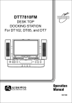
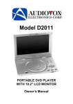
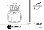
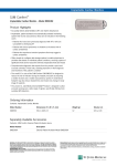
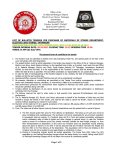
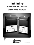
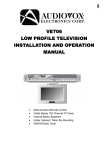
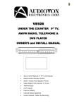
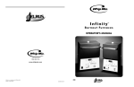
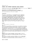
DKP102
UNDER COUNTER
DOCKING STATION
for DT102, DT85, DT7
MESSAGE
POWER
SOURCE
AUTO PRO.
PLAY
TV
CHANNEL
REC
RADIO TUNE
VOLUME
BASS BOOST
OPEN
RADIO BAND/ALARM OFF
®
CLOCK SET
STORE
CLOCK MODE
TIMER
MESSAGE
MIC
Operation and
Installation Manual
128-7350
Cautions And Warnings
RISK OF ELECTRIC SHOCK
DO NOT OPEN
The lightning flash with arrowhead symbol, within an equilateral triangle, is intended to
alert the user to the presence of un-insulated “dange The lightning flash with arrowhead
symbol, within an equilateral triangle, is intended to alert the user to the presence of uninsulated “dangerous Voltage” within the product’s enclosure that may be of sufficient
magnitude to constitute a risk of electric to persons.
The exclamation point within an equilateral triangle is intended to alert the user to the
presence of important operating and maintenance (servicing ) instructions in the literature
accompanying the appliance.
1. Placement
To prevent fire or electric shock, do not expose this appliance to rain or moisture. Do not place
the set on an unstable cart, stand, tripod, bracket or table to prevent it from falling. Keep the
DVD Player away from strong magnets, heat sources, direct sunlight, and excessive dust. If
the DVD Player is brought directly from a cold to a warm location, moisture may condense
inside the DVD Player. When you move it from a cold to a warm location, wait for about one
hour before operating the DVD Player, or remove the disc and leave the DVD Player turned
ON until the moisture evaporates.
2. Caution
Do not spill or spray liquid of any kind on or in the system (this may result in a fire or electric
shock). Do not place anything heavy on the DVD Player. To ensure proper ventilation and
proper operation, never cover or block the slots and openings with a cloth or other material.
Keep the DVD Player away from an open flame such as fire, candle etc.
It is hazardous to replace the battery incorrectly. Replace the battery only with the same or
equivalent type, in order to protect the environment, please dispose the dispose the battery
properly.
3. Warning
To reduce the risk of electric shock, do not perform any servicing other than that contained in
the operating instructions unless you are qualified to do so. There are no user-serviceable
parts inside. Refer all servicing to qualified service personnel. Servicing should be done only
by qualified service personnel.
4. Cleaning DVD Player
When cleaning, make sure the system is unplugged from the power source. Do not use liquid
cleaners or aerosol cleaners. Use a cloth lightly dampened with water for cleaning the exterior
of the system only.
5. Disc
Do not use irregularly shaped discs such as heart or star-shaped discs as they may cause the
DVD Player to malfunction. Do not stick paper, tape or glue on the disc. Do not expose the disc
to direct sunlight or heat sources. Do not touch the surface of disc. Handle the disc by its edge.
lean the disc by wiping the disc from the center out with a cleaning cloth. Remove the disc from
the DVD Player and store it in its case after playing. Software producers may intentionally fix
some playback operations of discs. Since this DVD Player plays discs according to the disc
contents the software producers designed, some playback features may not be available. Also
refer to the instructions supplied with the discs.
Materials Included In This Package
1) DKP102 Under Counter Docking Station for DT102, DT85 & DT7 (P/N: 136-3960) ~ 1pc
2) Hardware Package
1.6” (40.5mm) Phillips Head Screws – (4 pcs)
1.4” (35mm) Phillips Head Screws – (4 pcs)
1” (25mm) Phillips Head Screws – (4 pcs)
Washers – (4 pcs)
Spacers – 3/4" (4 pcs)
Spacers – 1/2" (4 pcs)
Spacers – 1/4" (4 pcs)
3) Remote Control (P/N: 136-3956) ~ 1pc
4) Adaptor AC to DC 100V/240V DC 12V 2.5A (P/N: 112-3542) ~ 1pc
5) AM / FM+BP Antenna (P/N: AMFM+BP) ~1pc
6) Paper Template (P/N: 128-7424) ~1pc
7) Antenna Adaptor L (P/N: 154-1130) ~ 2pcs
1
3
2
POWER
EJECT
FMM
ON/OFF
CHANNEL
SELECT
1
2
3
4
5
6
7
8
SOURCE
AUTO
MEMORY
SKIP/
SEARCH
ERASE/
WRITE
9
-
+
0
SEEK / CH
MUTE
VOLUME
PIX
SEARCH
SEARCH
ENTER
MENU
SETUP
RETURN
TV
AM
FM
4
6
7
TOOLS REQUIRED:
• Drill and Drill Bit
• Nail or Awl
• Philips Screwdriver
• Masking Tape
• Ruler or Tape Measure
• Scissors
• Countersink (Optional)
• Safety Glasses
• Mounting Template
1
REPEAT
DVD
RADIO
DISPLAY
BAND
RECALL
AUDIO
ZOOM
ANGLE
II PAUSE
5
SEEK / CH
A-B
STOP
TV/CATV
STORE
SUBTITLE
PLAY
Main Features
• Under Counter Docking Station for DT102, DT85, DT7
• 125 Channel Cable Ready TV Tuner
• AM / FM Radio•Alarm Clock
• AV Input
• Personal Message Recorder
• Bass Boost
• Countdown Timer
2
Connections & Setup
Mounting Instructions
Before Mounting
Empty contents from the selected counter which the unit will be mounted.
Clean the underside of the counter.
We recommend the unit be mounted to the front edge of the counter.
Mounting Procedure (Refer Figure 1)
1) Choose an appropriate mounting location underneath a cabinet or shelf. Close proximity to an
electrical outlet and a TV antenna or cable connection will facilitate a neat, easy installation.
Do not mount the DKP102 above a range or oven. Be sure that the location chosen will
provide adequate access to the electrical connection on the rear of the unit before
continuing.
2) If the location chosen has bottom edge molding it may be necessary to use the mounting spacers
provided to effectively lower the DKP102 below or even with the molding. Measure the distance
between the bottom and the bottom of the cabinet. For large molding choose a combination
of spacers which will allow the DKP102 to be secured to the bottom of the cabinet.
3) Measure the thickness of the bottom of the cabinet or shelf and the spacers chosen. Select
the shortest screw length which will secure the DKP102 to the bottom of the cabinet.
4) Cut out the template supplied and tape it in place onto the cabinet surface to be drilled. Center
punch the four holes indicated on the template and remove the template.
5 ) Carefully drill four 1/8” (5MM)holes at the locations marked above. Place the screws selected through
the DKP102 and then through the spacers(if required from the bottom-up).
6) Position the DKP102 and screw it in place using the selected screws. Do not over tighten.
7) Connect your TV antenna or cable system to the antenna connector on the rear of the DKP102.
8) Plug the AC adaptor into the rear of the DKP102 and then into the wall.
9) Attach the supplied AM/FM antenna to the AM/FM antenna jacks on the rear of the DKP102.
10) Route the wires safely away from heat and moisture sources and secure them in place using
the self adhesive wire mounting clip provided.
3
1
2
Template
3a
Cabinet surface
Spacer
3
DKP102
Side View
Mounting Screw
128-7424
To prevent heat damage, do not place
heating or cooking appliances beneath
this unit.
Install the unit as far as possible from
a source of noise. (For example
refrigerator, microwave oven, flourescent
lamp etc).
Figure 1
4
Main Features
Front Panel Controls
12
3
4
5
SOURCE
AUTO PRO.
6
7
8
PLAY
REC
MESSAGE
POWER
TV
RADIO TUNE
CHANNEL
20
VOLUME
19
18
BASS BOOST
17
OPEN
RADIO BAND/AlARM OFF
CLOCK SET
15
14
16
STORE
CLOCK MODE
13
TIMER
MESSAGE
12 11 10
MIC
9
1. Power Indicator– Bright red when power is on.
2. Power Button – To turn the DKP102 on or off.
3. Source Button – Press this button to select from the four available sources DVD, TV , AV, Radio.
4. Auto Pro. Button – When this button is pressed, all TV channels are searched and channels that are
detected with signals of sufficient levels are automatically stored in memory.
5. LCD Display Window – The LCD display shows the current time, source selected and radio
station.
6. Record Button – Press this button to record up to a 2 minute message.
7. Play Button – Press this button to playback the recorded message.
8. Numeric Buttons (1-5) – Used to recall the radio presets.
9. Mic – Microphone used for message recording .
10. Message Indicator – Flashes to indicate a message is waiting.
11. Timer Button – Used to set the timer function and turn off the timer buzzer when activated.
12. Clock Mode Button – Used to select the clock or alarm item to be set.
13. Store Button – Used to set the AM/FM presets into memory.
14. Radio Tune/Clock Set
– In Standby mode these buttons are used for setting hours, minutes, and to select
from 12 and 24 hour mode.
– In operation mode these buttons are used for radio tuning Up and Down.
15. Radio Band / Alarm Off Button – Radio Band selector. (Between FM1, FM2 and AM) Press this
button to turn off the alarm when activated.
16. Open Button – Used to unlock the shuttle housing.
17. Bass Boost Button – Used to increase the low frequency (Bass) response.
18. Volume Up/Down Button – Used to increase and decrease the volume level.
19. Channel Up/Down Button – Used to go to the next channel Up or Down.
20. Sensor Cover – Allows the remote control to operate the DKP102 and the installed shuttle
(DT102, DT85, DT7).
5
Main Features
Back Panel Controls
1
TV ANT
2
3
3
3
4
5
DC 12V
AUDIO R
AUDIO L
VIDEO IN
FM ANT
AM ANT
1. TV ANT – Connect the coaxial cable from an antenna or cable TV system to this jack.
2. DC 12V – Connect the supplied AC to DC adapter to this jack. The shuttle is designed for
negative ground 12V DC operation.
3. AV IN – The DKP102 will accept an AV input through the AV jacks located on the rear of the unit.
The video device could be a video game system, video camera, or other input device.
• VIDEO IN – Yellow
• AUDIO IN (L ) – White
• AUDIO IN (R) – Red.
4. FM ANT – Connect the FM radio antenna to this jack.
5. AM ANT – Connect the AM radio antenna to this jack.
6
Remote Control Operation
Battery Installation
Before attempting to operate your Remote
Control, install the batteries as described
below.
1) Turn the Remote Control face down. Using a
fingernail, lift the battery cover off.
2) Install two “AAA” batteries. Make sure that
proper polarity (+ or -) is observed.
3) Align the cover tabs with the remote control
and press down until the cover clicks.
The remote control will operate the VDS102T
and Audiovox shuttle models (DT102, DT85 or
DT7) It is not a universal remote control and
will not control equipment from other
BATTERY COVER
Remote Control Function Descriptions
POWER
1
EJECT
FMM
ON/OFF
CHANNEL
SELECT
1
2
3
4
5
6
7
8
9
-
+
SOURCE
2
3
4
5
6
7
8
9
10
11
AUTO
MEMORY
SKIP/
SEARCH
ERASE/
WRITE
0
SEARCH
SEARCH
ENTER
MENU
SETUP
RETURN
TV
12
13
14
15
16
17
18
19
20
21
SEEK / CH
MUTE
VOLUME
PIX
SEEK / CH
A-B
REPEAT
DVD
RADIO
DISPLAY
BAND
RECALL
STORE
AUDIO
ZOOM
ANGLE
SUBTITLE
II PAUSE
TV/CATV
PLAY
STOP
42
41
40
39
38
37
36
35
34
33
32
31
30
29
28
27
26
25
24
23
22
7
* Function control is available on the unit and the remote control.
** Used only when Shuttle (DT102, DT85 or DT7) is installed.
1. POWER Button*
Press this button to turn the DTT7810FM ON.
Press the button again to turn the DTT7810FM OFF.
2. SOURCE Button*
Use to select one of the four sources (DVD, TV, AV, and Radio)
3. AUTO MEMORY Button
(AUTO PROGRAM Button)**
When the AUTO MEMORY button is pressed, all channels are searched and
channels that are detected with signals of sufficient levels are automatically stored inmemory.
4. SKIP / SEARCH Button**
This button selects between SKIP ON and SKIP OFF mode. In “SKIP mode” the TV tuner will only
stop on channels that are programmed into memory. In SKIP OFF mode the TV will stop on all
active channels.
5. ERASE / WRITE Button**
While tuned to a channel, pressing this button will store or erase the channel from memory.
The word “ADD” and the stored channel numbers are displayed in “GREEN”. The word “ERASE” and
the erased channel numbers are displayed in “RED”.
6. SEEK / CHANNEL UP (5) Button**
Use this button to increase the TV channel number or radio station to the desired channel and to
scroll upward in menu options.
7. MUTE Button
Press this button to mute the audio.
Pressing the button again restores the sound to the previously set level.
8. ENTER Button**
Used to implement a selected setting or menu option.
9. LEFT (3) Button**
Allows the user to shift left in the menu options.
-OrSEARCH(6) Button**
When this button is pressed radio stations are searched in descending order and
the tuner will stop on the next active channel
10. MENU Button**
Allows the user to access the DVD root.
11. RETURN Button**
Not used in this model.
12. TV Mode Select Button**
Switches certain function keys on the remote control to TV functions.
13. DVD Mode Select button**
Switches certain function keys on the remote control to DVD functions.
14. DISPLAY Button**
Press to display the current DVD disc information.
or radio station
8
15. BAND Button**
Used to select the desired radio band (FM1/FM2/AM)
16. AUDIO Button**
Press this button to display and select the desired AUDIO language. Each time the button is
pressed, the language or track changes.
NOTE: The languages & tracks you can select vary from disc to disc.
17. ZOOM Button **
Press this button to enlarge the picture.
18. PAUSE(;)Button**
Allows the user to pause the playback. Pressing the pause button again will put the DVD player in
step (;4) mode allowing frame by frame playback. Press PLAY to return to normal playback
19. STOP(<)Button**
Disc playback will be stopped.
20. PREVIOUS(9)Button**
Allows the user to return to the previous chapter or track.
21. NEXT(:)Button**
Allows the user to skip to the next chapter or track.
22. REV(7)Button**
Allows the user to search in a backward direction at 2, 4, 8, and 20 times the normal speed.
23. FWD (8) Button**
Allows the user to search in a forward direction at 2, 4,8, and 20 times the normal speed.
24. PLAY (4)Button**
Press this button to activate the play mode when a disc is loaded into the disc compartment.
25. ANGLE Button**
Press this button to display and select the available camera angles. Each time the button is
pressed the angle will change.
NOTE: The number of angles vary from disc to disc.
26. SUBTITLE Button**
Press this button to display and select the available subtitle language in DVD mode. Each time the
button is pressed, the subtitle language changes.
NOTE: The type & number of languages for subtitles vary from disc to disc.
27. RECALL Button**
Used to recall the radio display and select preset stations.
28. STORE Button
Used to store radio presets into memory.
29. RADIO Button
Switches certain function keys on the remote to radio functions..
30. TV/CATV Button
Use this button to select regular (AIR) 69-channel broadcast TV or 125-channel cable TV (standard
Cable, HRC cable, or IRC cable). As the button is pressed, the on-screen display will cycle as
Follows:
AIR
CABLE-S
CABLE-H
9
CABLE-I
31. A-B Button
Allow the user to repeat playback of a DVD or CD from point A to point B.
32. REPEAT Button**
Allows the user to repeat a chapter, title, track, or all of a DVD, CD or MP3.
33. SEEK / CHANNEL DOWN (6) Button
Use this button to decrease the TV channel number or radio station to the desired channel and to
scroll downward in the menu options.
34. SETUP Button**
Allows the user to access the DVD setup menu and select various playback options (Display,
OSD Language, Defaults, Parental Control, Password, Exit Setup).
35. RIGHT (4) Button**
Allows the user to shift to the right in the menu options.
-OrSEARCH(5) Button**When this button is pressed radio stations are searched in
ascending order and the tuner will stop on the next active channel.
36. PIX Button (PICTURE SELECT)**
Each time this button is pressed, the OSD will display the “adjustment bars” for BRIGHTNESS,
CONTRAST, COLOR or TINT. Once the desired adjustment bar is displayed, use the VOLUME
UP/DOWN buttons to adjust the setting. The display will automatically turn off if no adjustments
are made within 6 seconds, or if any other button is pressed.
37. VOLUME (–) Button
Press this button to decrease the volume level.
38. VOLUME (+) Button
Press this button to increase the volume level.
39. NUMERIC KEYPAD
Allows the user to directly access specific TV channels, enter a parental control password and
select a specific track or chapter.
40. FMM ON/OFF
Not Used On This Model
41. CHANNEL SELECT Button**
Not Used On This Model
42. EJECT (5) Button**
Used to eject the disc.
10
System Panel Controls
DKP102 Operation
SETTING THE CLOCK:
NOTE: All settings are preformed in standby mode.
1.Selecting 12 or 24 hour display mode:
a.) Press the “clock mode” button once. The 12H/24H and AM/PM indicator will flash.
b.) Press the “radio tune/clock set” (-) or (+) button to toggle between 12 or 24 hour modes.
2. Setting the time:
a.) Press the “clock mode” button twice. The hours and minutes will flash.
b.) Press the “radio tune/clock set”(-) button to set the hour. This will also set AM/PM.
c.) Press the “radio tune/clock set”(+) button to set the minutes.
3. Selecting the alarm type:
a.) Press the “clock mode” button three times. The alarm indicator will flash.
b.) Press the “radio tune/clock set” (-) or (+) button to toggle between the three alarm options
(Alarm/Radio and OFF). A musical note will appear to indicate the radio has been selected.
A bell will appear to indicate the alarm tone has been selected. If the alarm OFF mode is
selected there will be no indicator displayed
4. Setting the alarm time:
a.) Press the “clock mode” button four times. The alarm indicator will be displayed and the hours
and minutes will flash.
b.) Press the “radio tune/clock set” (-) button to set the hour. This will also set AM/PM.
c.) Press the “radio tune/clock set” (+) button to set the minutes.
d.) Press the clock set button to turn off the alarm.
5.Recording a voice message
a.) Press the “REC” button until " REC " appears on the display.
b.) You can record a personal message up to 2 minutes long.
c.) When the message is complete press the “REC” button again to stop recording.
d.) The message indicator will flash to indicate a message is waiting.
e.) Press the “REC” button to delete the recorded message.
6.Playback of the voice message
a.) Press the “PLAY” button until " PLAY " appear on the display.
b.) Press the “PLAY” button again to stop playback of the message.
7.Timer countdown
- Maximum countdown time of 24 hours is allowed.
- Press the “TIMER” button to set the timer countdown.
- Press the “clock set” button to set the timer (-) for hours (+) for minutes.
- Press the “Timer” button to start the count down.
- Press the “Timer” button again to stop the count down.
- A buzzer will sound when the count down timer is completed
- Press the “Timer” button stop the buzzer.
Note: If the DKP102 is on and the alarm is set to the radio source the alarm will not sound. When the
alarm is set to the buzzer source, the buzzer will sound at the same time as the program audio.
11
Screen And System Panel Controls
RADIO MODE:
AM / FM – Press the source button until “Radio” appears on the display.
Press the “Radio Band” button to select the following: ( AM, FM1 and FM2)
Tune Radio Channel – Press the “Radio Tune” button either Up (+) or Down (-) to manually tune
through the frequencies. “-” Button to decrease the radio frequency and the
“+” button to increase the radio frequency.
Storing a Radio Station in Memory
1.) Press preset button 1 through 5 to select the preset channel number.
2.) Press the “Radio Tune” (+) or (-) button to tune to the desired radio station
3.) Press the “Store” button to enter the station into memory.
“Memo” will be displayed on the LCD display to
indicate the channel has been stored in memory.
–To store the next radio station in memory follow steps 1-3 above.
A maximum of 5 presets are available for each radio band (AM,FM1
and FM2).
Seek Tuning – Press and hold the Radio Tuner Up (+) or Down (-) button for 2 seconds to start seek
tuning . The DTT7810FM will search for and stop on the next active station.
Accessing Preset Stations – Pressing the “Recall” button repeatedly to access the available presets.
Manual Tuning – Press the Radio Tune Up (+) or Down (-) button repeatedly to manually tune to the
desired station.
NOTE: Consult the owners manual supplied with your shuttle (DT102, DT85, DT7) product for
complete DVD operating instructions.
12
Screen And System Panel Controls
DKP102 WITH DT102
Note: The DKP102 default source is the DVD shuttle. When power is turned OFF the DKP102
will default to the DVD shuttle.
SOURCE SELECTION:
1. DVD mode – When power is turned ON the DKP102 will be in DVD mode. When one of the
DVD shuttles is installed it will power ON a moment after the DPK102 is turned
ON.
2. TV mode – Press the “Source” button once.
– The DKP102 will be in TV tuner mode.
3. AV mode – Press the “Source” button twice.
– The DKP102 will be in AV mode. Any A/V source connected to the AV inputs on
the rear of the unit will be displayed.
4. Radio mode – Press the “Source” button three times.
– The DKP102 will be in Radio mode. The unit will be in the last band that was
selected (FM1, FM2, or AM)
13
Installing the Shuttle (DT102, DT85 and DT7 ) into the DKP102
Pressing the Open button will unlock the shuttle housing and it will drop down slightly. Pivot the housing
downward until it is at a right angle to the main unit.
4
1
Shuttle Housing
(Optional)
2
3
180°
AV1 Input
1) Lift the shuttle clamp (1) up to the top.
2) Install the lower (2) portion of the shuttle into the bottom of the shuttle housing (3).
3) Gently push the upper portion (4) of the shuttle into the shuttle housing and lower the shuttle
clamp (1) to hold the shuttle in position.
4) Rotate the shuttle housing until the back portion is visible. Gently tighten the locking screw on
the rear of the shuttle housing.
14
Troubleshooting
PROBLEM
SOLUTION
The DVD Player will not play
Make sure the AV IN/OUT switch on the side of the player
is in the OUT position for standard play.
Check the type of disc. This DVD Player only plays DVD's,
Audio CDs and MP3s.
Make sure that the shuttle is installed correctly.
Make sure the correct source (DVD) has been selected.
There is no sound from the
Speakers
Make sure the system settings are correct.
Make sure the volume is turned UP.
Make sure the sound setup of the DVD is correct.
Is the disc dirty or warped? Clean or replace disc.
Make sure no headphones are plugged into the
headphone jack.
There is no picture
Make sure the system is turned ON and in the correct
video mode.
Make sure your system connections are correct.
Poor AV performance
Is your disc dirty or warped? Clean or replace disc.
There is no sound when using
wireless headphones
Make sure the IRT switch is set to ON.
Make sure the batteries of the headphones are fresh.
The remote control does not
work
Make sure there aren’t any obstructions between the
remote control and the DVD Player.
Make sure the you are pointing the remote control at the
DVD Player.
Make sure the batteries are inserted correctly (check
polarity).
Replace weak batteries.
The words“Invalid Key” appear
on screen
The feature or action cannot be completed at this time because:
The disc’s software restricts it.
The disc’s software doesn’t support the feature (e.g., angles)
The feature is not available at the moment.
You’ve requested a title or chapter number that is out of
range.
Replacement Parts
Remote Control
136-3956
15
®
ELECTRONICS CORP .
90 DAY LIMITED WARRANTY
Applies to Audiovox Video Products
AUDIOVOX ELECTRONICS CORP. (the Company) warrants to the original retail purchaser of
this product that should this product or any part thereof, under normal use and conditions, be
proven defective in material or workmanship within ninety (90) days from the date of original
purchase, such defect(s) will be repaired or replaced with reconditioned product (at the
Company's option) without charge for parts and repair labor. A game controller, if supplied, is
similarly waranted for ninety (90) days.
To obtain repair or replacement within the terms of this Warranty, the product is to be delivered
with proof of warranty coverage (e.g. dated bill of sale), specification of defect(s), transportation
prepaid, to the Company at the address shown below.
This Warranty does not extend to the elimination of externally generated static or noise, to
correction of antenna problems, to costs incurred for installation, removal or reinstallation of the
product, or to damage to digital memory cards, discs, speakers, accessories, or electrical
systems.
This Warranty does not apply to any product or part thereof which, in the opinion of the
Company, has suffered or been damaged through alteration, improper installation, mishandling,
misuse, neglect, accident, or by removal or defacement of the factory serial number / bar code
label(s). THE EXTENT OF THE COMPANY'S LIABILITY UNDER THIS WARRANTY IS
LIMITED TO THE REPAIR OR REPLACEMENT PROVIDED ABOVE AND, IN NO EVENT,
SHALL THE COMPANY'S LIABILITY EXCEED THE PURCHASE PRICE PAID BY
PURCHASER FOR THE PRODUCT.
This Warranty is in lieu of all other express warranties or liabilities. ANY IMPLIED
WARRANTIES, INCLUDING ANY IMPLIED WARRANTY OF MERCHANTABILITY, SHALL BE
LIMITED TO THE DURATION OF THIS WRITTEN WARRANTY. ANY ACTION FOR BREACH
OF ANY WARRANTY HEREUNDER INCLUDING ANY IMPLIED WARRANTY OF
MERCHANTABILITY MUST BE BROUGHT WITHIN A PERIOD OF 24 MONTHS FROM DATE
OF ORIGINAL PURCHASE. IN NO CASE SHALL THE COMPANY BE LIABLE FOR ANY
CONSEQUENTIAL OR INCIDENTAL DAMAGES FOR BREACH OF THIS OR ANY OTHER
WARRANTY, EXPRESS OR IMPLIED, WHATSOEVER. No person or representative is
authorized to assume for the Company any liability other than expressed herein in connection
with the sale of this product.
Some states do not allow limitations on how long an implied warranty lasts or the exclusion or
limitation of incidental or consequential damage so the above limitations or exclusions may not
apply to you. This Warranty gives you specific legal rights and you may also have other rights
which vary from state to state.
U.S.A. : AUDIOVOX ELECTRONICS CORPORATION, 150 MARCUS BLVD., HAUPPAUGE,
NEW YORK 11788 • 1-800-645-4994
CANADA : CALL 1-800-645-4994 FOR LOCATION OF WARRANTY STATION SERVING YOUR AREA
© 2005 Audiovox Electronics Corporation
128-5556E
For Customer Service
Visit Our Website At
WWW.audiovox.com
Product Information, Photos,
FAQ’s Owner’s Manuals
© 2005 Audiovox Electronics Corp., Hauppauge, NY 11788
128-7350