1
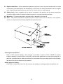
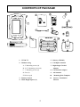
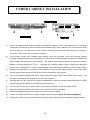
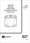
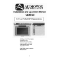
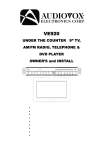
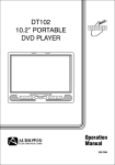
VE706
LOW PROFILE TELEVISION
INSTALLATION AND OPERATION
MANUAL
•
•
•
•
•
Multi-function Remote Control
Cable Ready 125 Channel TV Tuner
Internal Stereo Speakers
Under Cabinet / Table Top Mounting
AM/FM Radio Tuner
0
INTRODUCTION
WARNING – To prevent fire or shock hazard, do not expose this unit to moisture.
CAUTION: TO REDUCE THE RISK OF ELECTRIC
CAUT ION
SHOCK, DO NOT REMOVE COVER (OR BACK).
NO USER-SERVICEABLE PARTS INSIDE. REFER
SERVICING
TO
QUALIFIED
SERVICE
PERSONNEL.
This symbol is intended to alert the user to the presence of uninsured “dangerous
voltage” within the product’s enclosure that may be of sufficient magnitude to
constitute a risk of electric shock to persons.
This symbol is intended to alert the user to the presence of important operating and
maintenance (servicing) instructions in the literature accompanying the appliance.
TO PREVENT ELECTRIC SHOCK: DO NOT USE THIS POLARIZED AC PLUG
WITH AN EXTENSION CORD, RECEPTACLE OR OTHER OUTLET UNLESS
THE BLADES CAN BE FULLY INSERTED TO PREVENT BLADE EXPOSURE.
1
INFORMATION
This equipment generates and uses radio frequency energy and if not installed and used properly, that is,
in strict accordance with the manufacture’s instructions, may cause or receive unwanted interference.
This unit complies with FCC Rules Part 15, which are designed to provide reasonable protection against
interference in a residential installation. However, there is no guarantee that interference will not occur in a
particular installation. If this equipment does cause harmful interference to radio or television reception,
which can be determined by turning the equipment off and on, the user is encouraged to try to correct the
interference by one or more of the following measures:
- Reorient or relocate the receiving antenna
- Increase the separation between the equipment and receiver
- Connect the equipment into an outlet on a circuit different from that to which the receiver is
connected
- Consult the dealer or an experienced radio/TV technician for help
NOTE:
Record Model Number and Serial Number in the space provided below. Refer to these numbers if you
need to call your AUDIOVOX dealer regarding this product.
MODEL No.
SERIAL No.
_____________________
_______________________
2
IMPORTANT SAFETY INFORMATION
1.
Read Instructions – All the safety and operating instructions should be read before the product is
operated.
2.
Retain Instructions – The safety and operating instructions should be retained for future reference.
3.
Head Warnings – All warnings on the product and in the operating instructions should be adhered to.
4.
Follow Instructions – All operating and use instructions should be followed.
5.
Cleaning – Unplug this product from the wall outlet before cleaning. Do not use liquid or aerosol
cleaners. Use a damp cloth for cleaning.
Do not apply pressure to the LCD screen.
Excess
pressure can damage the screen.
6.
External Accessories – Do not use external accessories not recommended by the product
manufacturer, as they may cause a hazard.
7.
Water and Moisture – Do not use this product near water – for example, near a bath tub, kitchen
sink, laundry tub, in a wet basement, near a swimming pool, or similar situations.
8.
Mounting considerations – Do not place this product on an unstable cart, stand, tripod bracket, or
table. The Product may fall, causing serious injury to a child or adult, and serious damage to the
product. Use only with a cart, stand, tripod, bracket, or table recommended by the manufacture, or
sold with the product. Any mounting of the product should follow the manufacture’s instructions, and
should use the mounting accessories recommended by the manufacturer.
9.
Carts - A product and cart combination should be moved with care. Quick
stops, excessive force, and uneven surfaces may cause the product and cart
combination to overturn.
10. Ventilation – Slots and openings in the cabinet are provided for ventilation
and to ensure reliable operation of the product and protect it from overheating. These openings
must not be blocked or covered. The openings should never be blocked by placing the product on a
bed, sofa, rug, or other similar surface. This product should not be placed in a built-in installation
such as a bookcase or rack unless proper ventilation is provided.
11. Power Sources – This product should be operated only from the type of power source indicated on
the marking label. If you are not sure of the type of power supply in your home, consult your product
dealer or local power company.
12. Grounding or Polarization – This product may be equipped with a polarized alternating current line
plug (a plug having one blade wider than the other). This plug will fit into the power outlet only one
way. This is a safety feature. If you are unable to insert the plug fully into the outlet, try reversing the
3
plug. If the plug still cannot be inserted, contact your electrician to replace your outlet. Do not defeat
the safety purpose of the polarized plug.
13. Power-Cord Protection – Power-supply cords should be routed so that they are not likely to be
walked on or pinched by items placed upon or against them paying particular attention to cords at
plugs, convenience receptacles, and the point where they exit from the product.
14. Outdoor Antenna Grounding – If an outside antenna or cable system is connected to the product,
be sure the antenna or cable system is grounded in order to provide some protection against voltage
surges and built-up static charges. Article 810 of the National Electrical Code, ANSI/NFPA 70, provide
information with regard to proper grounding of the mast and supporting structure, grounding of the
lead-in wire to an antenna discharge unit, size of grounding conductors, location of antennadischarges unit, connection to grounding electrode (Refer to the figure on page 6).
15. Lightning – For added protection of this product during a lightning storm, or when it is left
unattended and unused for long periods of time, unplug it from the wall outlet and disconnect the
antenna or cable system. This will prevent damage to the product due to lightning and power-line
surges.
16. Power Lines – An outside antenna system should not be located in the vicinity of overhead power
lines or other electric light or power circuit, or where it can fall into such power lines or circuits.
When installing on outside antenna system, extreme care should be taken to keep from touching
such power lines or circuits as contact with them might be fatal.
17. Overloading – Do not overload wall outlets, extension cords, or integral convenience receptacles, as
this can result in a risk of fire or electric shock.
18. Object and Liquid Entry – Never push objects of any kind into this product through openings in the
chassis as they may touch dangerous voltages points or short-out parts that could result in a fire or
electric shock. Never spill liquid of any kind on the product.
19. Servicing – Do not attempt to service this product yourself as opening or removing covers my
expose you to dangerous voltages or other hazards. Refer servicing to qualified service personnel.
20. Damage Requiring Service – Unplug this product from the wall outlet and refer servicing to qualified
service personnel under the following conditions.
A.
When the power-supply cord or plug is damaged.
B.
If liquid has been spilled, or an object has fallen into the product.
C.
If the product has been exposed to rain or water.
D.
If the product does not operate normally by following the operating instructions. Adjust only
those controls that are covered by the operating instructions, as an improper adjustment of
other controls may result in damage and will often require extensive work by a qualified
technician to restore the product to it’s normal operation.
E.
F.
If the product has been dropped or damaged in any way.
When the product exhibits a significant change in performance – this indicates a need or
service.
4
21. Replacement Parts – When replacement parts are required, be sure the service technician has used
replacement parts specified by the manufacturer or that have the same characteristics as the original
part. Unauthorized substitutions may result in fire, electric shock or other hazards.
22. Safety check - Upon completion of any service or repairs to this product, ask the service technician
to perform safety checks to determine that the product is in proper operating condition.
23. Mounting – The product should be mounted only as directed in this manual.
24. Heat – The product should be situated away from heat sources such a radiators, heat registers,
stoves, or other products (including amplifiers) that produce heat.
- Cable System Installation:
Note to CATV system installer: “This reminder is provided to call the CATV (CABLE-TV) system
installer’s attention to article 820-40 of the NEC, that provides guidelines for proper grounding and, in
particular, specified that the cable ground shall be connected to the grounding system of the building,
as close to the point of cable entry as practical”
- Under cabinet mounting:
CAUTION: to reduce the risk of fire, do not place any heating or cooking product beneath this unit.
5
Table Of Contents
Before You Begin
Introduction................................................. 1
Important Safety Information..................... 3
Table of Contents ....................................... 6
Contents of package .................................. 7
Installation
Under Cabinet Installation.......................... 8
Countertop/Desktop Installation................ 9
Front Panel Controls................................... 10
Rear Panel Connectors............................... 11
LCD Control Functions…………………….. 12
Remote Control Functions
Battery Installation...................................... 13
Modes of Operation
Remote Control Functions......................... 14
Operation...................................................... 15
Initial Set up................................................... 15
Channel Tuning Set up.................................. 15
Positioning the Screen................................... 15
Setting the Time............................................. 15
Setting and Activating The Alarm................... 16
Deactivating Alarm......................................... 16
Setting the Alarm Tones................................. 16
Setting the Cable TV Mode............................ 16
Setting the Air TV Mode................................. 17
Setting the Presets (In FM, AM or TV
Technical Specifications
Modes)........................................................... 17
Troubleshooting Check List
Technical Specifications............................. 18
Troubleshooting Check List……………….. 19
6
CONTENTS OF PACKAGE
FM/AM
PWR
TV
MUTE
VOL
CH ENT CH
VOL
SEEK
AP
1
2
3
DEL
4
5
6
ADD
7
8
9
0
1. VE706 TV
5. Battery (CR2025)
2. Hardware bag
6. FM Dipole Antenna
A. 2” Mounting screws (4)
7. Right Angle Coaxial
B. 2-1/2” Mounting screws (4)
C. 3” Mounting screws (4)
Adaptor
8. FM Antenna Adaptor
D. Foot (4)
9. AM Antenna
E. Hole cap (4)
10.
3. Remote Control
Mounting Hole Template
11. Owners / Installation
4. Multi Height Spacer (4)
Manual
7
UNDER CABINET INSTALLATION
1)
Choose an appropriate mounting location underneath a cabinet or shelf. Close proximity to an electrical
outlet and a TV antenna or cable connection will facilitate a neat, easy installation. Do not mount the VE706
above a range or oven. Be sure that the location chosen will provide adequate access to the electrical
connection on the rear of the unit before continuing.
2)
If the location chosen has a bottom edge molding it may be necessary to use the mounting spacers
provided to effectively lower the VE706 below or even with the molding. Measure the distance between the
edge molding and the bottom of the cabinet. The spacers and mounting holes are stepped to achieve
different mounting heights from .5” to 1”. Adjusting the mounting height is done by lifting and rotating the
spacer in the mounting hole. Choose a spacer height, which will allow the VE706 to clear the edge molding.
3)
Measure the thickness of the bottom of the cabinet or shelf and the spacer height chosen. Select the
shortest screw length, which will secure the VE706 to the bottom of the cabinet.
4)
Cut out the template supplied and tape it in place onto the cabinet surface to be drilled. Center punch
the
5)
Carefully drill four 1/8″ holes at the locations marked above. Place the screws selected through the VE706
four holes indicated on the template and remove the template.
and then through the spacers (if required from the bottom-up)
6)
Connect your TV antenna or cable system to the antenna connector on the rear of the VE706.
7)
Attach the FM Dipole Antenna and position the antenna for the best reception.
8)
Attach the AM Antenna and position the antenna for the best reception.
9)
Position the VE706 and mount it in place using the selected screws. (Note: Do not over-tighten.)
10) Plug the AC power cable into the wall outlet. Route the wires safely away from heat and moisture sources.
8
COUNTERTOP/DESKTOP INSTALLATION
NOTE: Use caution to avoid damaging the LCD screen and the main unit when converting this
unit from an under-counter unit to a countertop unit. Leave the protective plastic on the screen
until this procedure is completed.
1)
Place the unit (with the screen facing up) on a soft padded surface.
2)
Pivot the screen so that it is perpendicular to the front of the unit and then turn it sideways.
3)
Remove the hinge guide covers (#1) using a flat blade screwdriver inserted into the removal slots.
Unscrew the mounting screws (#2). Remove the connector from the unit (#3), be careful not to
damage the screen (#5).
4)
Turn the unit over and remove the blank cover (#4)
5)
Connect the plug of the LCD monitor into the connector (#3). (Note: align the “L” and “R”
stamped on the screen mounting bracket with the “L” and “R” molded into the connector
housing).
6)
Replace the screws and slide the hinge guide covers onto the unit, be careful to not damage the
7)
Insert the rubber pieces (#6) (Foot, Mounting Cap - please refer to the illustration above) into the
wires. (Note: Do not over-tighten).
unit. Install the blank cover on the unused port.
9
FRONT PANEL CONTROLS
18
19
12:00
ON/OFF
SET
ADD
DEL
AP
TV
FM
VOLUME
AM
CH
P1
P2
P3
P4
MUTE
SEEK
1
9
2
10
3
11
4
12
5
13
6
14
7
15
8
16
17
19
1)
ON/OFF BUTTON – Power ON/OFF.
2)
SET BUTTON – Press this button to set the TIME, ALARM, TV Mode.
3)
ADD BUTTON – Press this button to add a selected channel.
4)
DEL BUTTON – Press this button to delete a selected channel.
5)
AP BUTTON – Press and Hold this button to start the Auto Program feature.
6)
TV BUTTON – Press this button to select TV mode and Press and Hold this button to change the
aspect ratio.
7)
FM BUTTON – Press this button to select FM Radio mode.
8)
AM BUTTON – Press this button to select AM Radio mode.
9)
MUTE BUTTON – Press this button to mute the audio (++++ will appear and blink on the display
when the system is muted).
10) P4 - BUTTON – Selected Preset Channel “4” in the Radio or TV mode
11) P3 - BUTTON – Selected Preset Channel “3” in the Radio or TV mode.
12) P2 - BUTTON – Selected Preset Channel “2” in the Radio or TV mode.
13) P1- BUTTON – Selected Preset Channel “1” in the Radio or TV mode.
14) VOLUME UP (X) BUTTON – Press this button to raise the volume.
15) VOLUME DOWN (W) BUTTON – Press this button to lower the volume.
16) SEEK BUTTONS (TS-Right Side) – Press these buttons to go to next available channel with
sufficient signal strength.
17) CHANNEL BUTTONS (TS-Left Side) – Press these buttons to go to next available channel.
18) DISPLAY WINDOW – Displays the channel/station number, time, and selected source.
19) REMOTE INFRARED SENSORS-These sensors receive infrared command signals from the hand
held remote control unit.
10
REAR PANEL CONNECTIONS
1
2
3
4
1)
AC LINE CORD – Connects to AC power outlet.
2)
FM ANTENNA – Allows the VE706 to be connected to a 75-Ohm external coaxial antenna for the
reception of FM broadcast signals.
3)
AM ANTENNA - Allows the VE706 to be connected to an external antenna for the reception of AM
broadcast signals.
4)
TV ANTENNA (75 OHM ANTENNA CONNECTOR) -Allows the VE706 to be connected to a 75ohm external coaxial antenna or cable TV system.
11
LCD Control Functions
1. MENU Button – When pressed, the LCD control MENU is displayed.
2. SEL Button – Used to enter the picture menu. Highlight the menu item to be changed using the
UP/DOWN buttons and then press Select to adjust the highlighted item..
3. UP Button – Scrolls upward through menu items, also adjusts selected item in upward (increase)
direction.
4. DOWN Button – Scrolls downward through menu items; also adjusts selected item; in downward
(decrease) direction.
NOTE: To reset all of the picture settings to the factory settings, highlight RESET and press the SEL
button.
12
BATTERY INSTALLATION
1) Turn the Remote Control face down. Place a fingernail, or coin in the open slot, slide battery holder
out.
2) Install the CR2025 battery into its proper slot. (Note: Be sure to observe the correct polarity
when inserting the battery).
3) Slide the battery holder in until it clicks.
13
REMOTE CONTROL FUNCTIONS
6
7
PWR
FM/AM
TV
8
1
2
MUTE
VOL
9
10
CH ENT CH
3
4
VOL
SEEK
A/P
1
2
3
DEL
11
4
5
6
ADD
12
7
8
9
0
5
1. POWER ON/OFF (PWR)
Press this button to turn the VE706 on. Press the button again to turn the VE706 off.
2. ENTER (ENT)
This button is used after entering the channel number.
3. CHANNEL UP/DOWN (S T)
Press these buttons to advance to the next higher or lower channel.
4. AUTO PROGRAM (AP)
Press this button for a half second to scan and store all active TV channels in memory.
5. NUMERICAL BUTTONS (1~9, 0)
Press these buttons to make a direct channel selection.
6. VOLUME UP/DOWN BUTTONS (S T)
Press these buttons to increase or decrease the volume.
7. FM/AM
Each time this button is pressed, the VE706 will alternate between AM and FM.
8. TV BUTTON (TV)
Used to select TV function, Press and Hold to change the TV aspect ratio.
9. MUTE BUTTON (MUTE)
Press this button to mute the audio (++++ will blink on display).
10. SEEK BUTTONS (IW XI)
Use these buttons to advance to the next higher or lower channel/station with sufficient signal
strength.
11. DELETE BUTTON (DEL)
Press this button to delete the selected channel from memory.
12. ADD BUTTON (ADD)
Press this button to add the selected channel to memory.
14
OPERATION
Initial Setup: This unit defaults to cable TV mode. When the unit is first powered on, it will detect
the cable system and auto-program the TV tuner to the available stations. Please wait while the
unit auto-programs before attempting to operate the unit.
During this time the unit will not
respond to any commands. The unit will respond normally once the cable mode and channel
search mode is concluded.
CHANNEL TUNING SET UP
In addition to normal broadcast reception of VHF and UHF channels, if you are Cable TV subscriber, your
new TV is capable of receiving many unscrambled Cable channels without the use of a converter box.
When set to broadcast (AIR) TV, it receives CH2-CH69. When set to one of the CATV modes (STD, HRC,
or IRC) it receives CH1-CH125. NOTE: Most cable companies broadcast in STD Mode
After a power interruption, the unit will go into a cable mode search (HRC, IRC, STD) and channel
search mode automatically. During this time the unit will not respond to any commands. The
unit will respond normally once the cable mode and channel search mode is concluded.
POSITIONING THE SCREEN
Press the screen lock button and pivot the screen forward until a comfortable viewing angle is reached.
The screen may also be rotated from side to side. Do not force the screen beyond its rotational limit. The
VE706 is now ready for use.
Pressing the PWR button on the unit or the remote will turn the system on or off. Remember to turn the
unit off and pivot the screen to the closed position when not in use.
SETTING THE TIME
NOTE: All settings (except setting the presets) are performed with the VE706 turned off.
1) Press the SET button and the minutes will flash.
2) Use the CH up/down button to set the minutes.
3) Press the SEEK button to toggle between the hour and minutes.
4) Use the CH up/down button to set the hour. (Check AM/PM indicator)
5) Press the ON/OFF button to return to the time display.
15
SETTING and ACTIVATING ALARM
NOTE: The VE706 must be turned “OFF” when performing the following procedure.
1) Press the SET button twice to enter the alarm mode, press the P3 button to toggle between the
active and deactivated mode.
NOTE: If a series of dashes appear (--: --), the Alarm is DEACTIVATED.
2) Press the CH up/down buttons to set the desired hour/minute. When setting the alarm, check the
AM/PM indicator to assure the proper setting.
3) Press the SEEK buttons to toggle between the hours and minutes.
4) Press the On/OFF button. The alarm is now set and activated. Once the alarm is set it will sound
each day at the same time as long as it is activated.
DEACTIVATING ALARM
1) Press the SET button twice to enter the alarm mode.
2) Press the P3 button once. The set time will disappear from the Display Window and a series of
dashes (--: --) will appear, Alarm DEACTIVATED mode.
3) Press the ON/OFF button. The alarm is now deactivated.
NOTE: The set time will be stored in memory and can be reactivated whenever desired by
performing step 1) of the ACTIVATING ALARM procedure.
SETTING THE ALARM TONES
1) Press the SET button twice (power off).
2) Press the P4 button once to hear the alarm tone.
NOTE: Alarm must be in the “Activated” mode to hear tones.
3) Each time CH UP/DOWN button(s) is pressed it will select a different alarm tone.
4) Press the ON/OFF button to confirm the selected tone.
5) When the alarm sounds, press the set button to turn it off.
SETTING THE CABLE TV MODE
1) Press the SET button three times to enter the TV/Cable configuration mode.
2) CABLE or AIR will appear on the display.
3) Press the SEEK button to select Cable mode.
4) Press the CH UP/DOWN button(s) to select the desired cable mode (STD/IRC/HRC).
5) When the desired mode is reached, press the ON/OFF button to confirm.
16
SETTING THE AIR TV MODE
1) Press the SET button three times to enter the TV/Cable configuration mode.
2) Press the SEEK button to select the AIR mode.
3) Press the ON/OFF button to confirm.
SETTING THE PRESETS (IN AM, FM OR TV MODES)
1) Tune the desired channel/station.
2) Press the SET button and the display flashes.
3) Press desired preset (P1, P2, P3 & P4) to confirm the selection.
17
TECHNICAL SPECIFICATIONS
GENERAL
Power Supply
AC100-240V ~50/60Hz 25watts
Operating Temperature
0°~40°C / 32°~104°F
Operating Humidity
10% ~ 75%
Body Size
400 X 280 X 56mm / 15.7” x 11.0” x 3.25”Inches
Weight
3.2 Kg / 4.2Lbs
DISPLAY
Illumination
CCFL Edge Lit Tube
Backlighting Life Expectancy
10,000Hrs
Resolution
1440(W) X 234(H)
Screen
7” TFT LCD (16:9)
TV Channels
VHF/UHF (2-69), CABLE TV (STD,IRC,HRC) 1 - 125
TV System
NTSC
MISC
Radio Frequency Range
Audio output
AM 530KHz – 1710KHz
FM 87.5MHz – 107.9MHz
1.2W / 8ohm (2 Speakers)
18
TROUBLESHOOTING CHECK LIST
Problem
Poor Reception
Solution
•
Verify Tuner setting matches Antenna/Cable
broadcast system.
Remote control will not function
•
Verify that the sensor on the VE706 is not
obstructed.
•
Verify
that
the
infrared
LED
on
the
transmitter is not obstructed.
•
Check the condition of the remote control
battery.
Black and White Reception
•
Verify Tuner setting matches Antenna/Cable
broadcast system. Try other system types
with the instructions on page 16 of this
manual.
19
90 DAY LIMITED WARRANTY
Applies to Audiovox Video Products
AUDIOVOX ELECTRONICS CORP. (the Company) warrants to the original retail purchaser of this product that should this product or any part thereof, under normal use and
conditions, be proven defective in material or workmanship within ninety (90) days from the date of original purchase, such defect(s) will be repaired or replaced with
reconditioned product (at the Company's option) without charge for parts and repair labor. A game controller, if supplied, is similarly waranteed for ninety (90) days.
To obtain repair or replacement within the terms of this Warranty, the product is to be delivered with proof of warranty coverage (e.g. dated bill of sale), specification of
defect(s), transportation prepaid, to the Company at the address shown below.
This Warranty does not extend to the elimination of externally generated static or noise, to correction of antenna problems, to costs incurred for installation, removal or
reinstallation of the product, or to damage to digital memory cards, discs, speakers, accessories, or electrical systems.
This Warranty does not apply to any product or part thereof which, in the opinion of the Company, has suffered or been damaged through alteration, improper installation,
mishandling, misuse, neglect, accident, or by removal or defacement of the factory serial number/bar code label(s). THE EXTENT OF THE COMPANY'S LIABILITY
UNDER THIS WARRANTY IS LIMITED TO THE REPAIR OR REPLACEMENT PROVIDED ABOVE AND, IN NO EVENT, SHALL THE COMPANY'S LIABILITY EXCEED
THE PURCHASE PRICE PAID BY PURCHASER FOR THE PRODUCT.
This Warranty is in lieu of all other express warranties or liabilities. ANY IMPLIED WARRANTIES, INCLUDING ANY IMPLIED WARRANTY OF MERCHANTABILITY,
SHALL BE LIMITED TO THE DURATION OF THIS WRITTEN WARRANTY. ANY ACTION FOR BREACH OF ANY WARRANTY HEREUNDER INCLUDING ANY
IMPLIED WARRANTY OF MERCHANTABILITY MUST BE BROUGHT WITHIN A PERIOD OF 24 MONTHS FROM DATE OF ORIGINAL PURCHASE. IN NO CASE
SHALL THE COMPANY BE LIABLE FOR ANY CONSEQUENTIAL OR INCIDENTAL DAMAGES FOR BREACH OF THIS OR ANY OTHER WARRANTY, EXPRESS OR
IMPLIED, WHATSOEVER. No person or representative is authorized to assume for the Company any liability other than expressed herein in connection with the sale of
this product.
Some states do not allow limitations on how long an implied warranty lasts or the exclusion or limitation of incidental or consequential damage so the above limitations or
.
exclusions may not apply to you. This Warranty gives you specific legal rights and you may also have other rights which vary from state to state
U.S.A. : AUDIOVOX ELECTRONICS CORPORATION, 150 MARCUS BLVD., HAUPPAUGE, NEW YORK 11788 1-800-645-4994
CANADA : CALL 1-800-645-4994 FOR LOCATION OF WARRANTY STATION SERVING YOUR AREA
© 2006 Audiovox Electronics Corporation
128-5556E
© 2006 Audiovox Electronics Corporation
20
128-7645