1
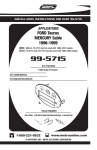
INSTALLATION GUIDE FOR:
Model : CDI-100R
ISO-DIN MOUNT CD CHANGER
CONTROLLER / FM MODULATOR
Form No. 128-5260
PARTS LIST
Item
1
2
3
4
Description
CDI-100 CDC Controller
M4 x .8P x 8mm
M5 x .8P x 8mm
ISO-DIN Trim Ring
Quantity
1
4
4
1
RADIO/MAP POCKET DIS-ASSEMBLY
1. Remove factory radio dash panel to expose sub-dash.
2. Remove radio/map pocket assembly from the subdash. Retain the factory supplied mounting hardware.
3. Disconnect the factory radio harness and antenna
lead. Loosen the radio mounting screws on one side of
the radio/map pocket assembly.
4. Remove the pocket attached to the factory radio
mounting bracket and discard as it will not be used in
conjunction with the CDI-100R.
CDI-100R PREPARATION
1. Install the CDI-100R into the bracket assembly below
the factory radio. Make sure to align the CDI-100R face
with the front of the factory radio. Select the appropriate size screws, Item #2 or Item #3, from CDI-100R
hardware bag to secure the CDI-100R to the factory
radio bracket. Secure the factory supplied radio mounting screws. (See Fig. 1)
CAUTION: Do not use longer screws or damage to
the interior parts of the unit may occur.
2. Plug the 8-pin circular DIN connector from the remotely
mounted CD changer into the mating socket on the
rear of the CDI-100R. (See Fig. 2)
3. Plug the cable from the vehicle antenna into the female
antenna connector on the CDI-100R.
4. Plug the male antenna connector from the CDI-100R
into the antenna socket on the factory radio.
5. Re-connect the power/speaker connector(s) to the
factory radio.
6. Connect the Green w/White Stripe, Orange w/White
Stripe, and Black w/White Stripe wires to constant +12
volts, switched +12 volts, and ground, respectively, as
indicated in Fig. 2.
7. After completing the wiring in steps 2 through 5,
perform a function test of the radio and CDI-100R to
confirm correct operation (ignition switch must be "on"
during testing and adjustment).
ADJUSTMENT OF FM OUTPUT FREQUENCY
The output frequency of the CDI-100R is factory set to
89.1 MHz. If there is interference from a local station on
89.1 MHz., the output frequency of the CDI-100R can be
changed to 88.7 MHz. by sliding the switch on the bottom
of the chassis to the "88.7 MHz." position.
ADJUSTMENT OF AUDIO LEVEL
The audio level from the CDI-100R is factory-set to
provide the correct volume balance between radio and
CD changer in the majority of installations and usually will
not require any adjustment. If, however, a large difference in volume level is noted when switching between
CD changer and FM radio operation, the audio level from
the CD changer may be adjusted as follows:
1. With the CD changer off, tune to an FM station and
adjust the volume control on the radio to a normal
listening level.
2. Leaving the volume control at the setting, turn on the
CD changer and tune the radio to the modulator output
frequency (89.1 or 88.7 MHz.).
3. Select a LOUD section of the CD. If the volume level
is comparable to that of the FM station in step 1, no
adjustment is necessary. If it is noticeably louder or
more quiet than that of the radio station, use a
#0 Phillips screwdriver to adjust the "AUDIO LEVEL"
control on the bottom of the chassis so that the CD
changer volume is comparable to that of the radio
station.
IMPORTANT: If the CDI-100R audio level is adjusted
too high, it may result in unacceptable levels of distortion during loud sections of CD's. If set too low, it may
result in poor signal/noise levels during CD changer
operation.
RADIO/CDI-100R INSTALLATION
1. Dress the wires so there is no interference when
installing the factory radio/CDI-100R assembly into
sub-dash.
2. Re-install the factory radio/CDI-100R bracket assembly into the vehicle's sub-dash, utilizing the factory
supplied mounting hardware previously removed.
3. Replace the dash panel.
Fig. 1
FACTORY RADIO/CDI-1OOR ASSEMBLY
FRONT VIEW
FACTORY
RADIO BRACKET
(TYPICAL)
FACTORY RADIO
(TYPICAL)
FACTORY
SUPPLIED RADIO
MOUNTING SCREWS
ALIGN FRONT OF
CDI-100R WITH FRONT
OF FACTORY RADIO
CDI-100R
CDI-100R
MOUNTING SCREWS
(ITEM #2 or #3)
AUDIO LEVEL ADJUSTMENT
(ON BOTTOM OF CHASSIS)
FREQUENCY SWITCH
(ON BOTTOM OF CHASSIS)
FACTORY RADIO/CDI-1OOR ASSEMBLY
Fig. 2
REAR VIEW
FACTORY RADIO
POWER/SPEAKER CONNECTOR
(LOCATION AND TYPE WILL VARY)
GROUND
(BLACK w/WHITE STRIPE)
FUSE 2A
TO
+12 VOLTS SWITCHED
(ORANGE w/WHITE STRIPE)
FUS
E 5A
TO
+12 VOLTS CONSTANT
(GREEN w/WHITE STRIPE)
ANTENNA SOCKET
(LOCATION AND TYPE WILL VARY)
MALE ANTENNA CONNECTOR
FEMALE ANTENNA CONNECTOR
FROM VEHICLE ANTENNA
8-PIN DIN CONNECTOR
FROM CD CHANGER