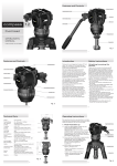
1
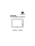
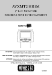
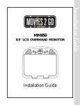
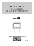
AVXMTGHR1MA
7” LCD MONITOR
FOR REAR SEAT ENTERTAINMENT
OPERATION AND INSTALLATION MANUAL
Important Notice
Installation of headrest products require careful planning and preparation. Be extremely careful
with seats that have airbags built into them. Keep wiring away from any air bag wiring (usually
identified by yellow connectors and yellow wire jackets). Damage to air bag wiring can result in
personal injury to vehicle occupants. If you have any questions regarding wire routing or
installation in a vehicle, please contact Audiovox Technical Support at 1-800-225-6074.
When connecting power and ground in a mobile video installation, insure that the ACC wire is
fused at the point where it is connected to the vehicle ACC wiring. Failure to do so can result in
damage to the vehicle if a short circuit develops between the vehicle connection point and the
mobile video product.
An LCD panel and/or video monitor may be installed in a motor vehicle and visible to the driver if
the LCD panel or video monitor is used for vehicle information, system control, rear or side
observation or navigation. If the LCD panel or video monitor is used for television reception,
video or DVD play, the LCD panel or video monitor must be installed so that these features will
only function when the vehicle is in “park” or when the vehicle’s parking brake is applied.
An LCD panel or video monitor used for television reception, video or DVD play that operates
when the vehicle is in gear or when the parking is not applied must be installed to the rear of the
driver’s seat where it will not be visible, directly or indirectly, to the operator of the motor vehicle.
Licensed under one or more of the following patents:
Patent NOS. 7,245,274 , 6,899,365 and 6,678,892
FEATURES
• 7” Digital TFT (Thin Film Transistor) Active Matrix LCD (Liquid Crystal Display) Monitor
• OSD (On Screen Display) for control of picture quality and functions
• Two Audio / Video Source inputs (AV and AUX).
• Screen mode selection (4:3, 16:9)
• Full function remote control
• IR headphone (optional)
SPECIFICATIONS
Type
TFT Active Matrix LCD
Resolution
480x234
Pixels
336,960
Operation Temperature
32 ~113º F (0 ~ 45º C)
Storage Temperature
-4 ~ 149º F (-20 ~ 65º C)
Backlit life
20,000 Hours
Video Display System
NTSC / PAL
Headphone Audio Output
0.03W @ 32 ohms
Power Source
Dimension (L x W x H)
12 VDC
147mm x 275mm x 200mm
5.7in x 10.8in x 7.8in
Specifications subject to change without notice.
3
MATERIAL TO USE IN THIS PACKAGE:
1) AVXMTGHR1MA System Monitor (AVXMTGHR1MA )
NOTE: The AVXMTGHR1DA monitor has been designed
with interchangeable covers. The headrest cover as
supplied is covered with shale colored vinyl. Black vinyl
and pewter vinyl can replace the shale colored vinyl.
.
NOTE:Headrest cable is included with the monitor.
LCD REMOTE
1) Remote Control
(P/N 136-5436) - (1pc)
2) AV Adapter Cable
(P/N 112B3227)-(1pc)
VIDEO
SELECT
MENU
MODE
SELECT
3) AV IN / Power Cable, 8 Pin Din to 3 RCA (Red)
(P/N 112-4309)-(1pc)
4) Shrink Tubing, Black
(P/N 138-1495 )-(1pc)
5) Black Vinyl Headrest Cover
(P/N 126-1377)-(1pc)
6) Pewter Vinyl Headrest Cover
(P/N 126-1378)-(1pc)
7) Support Tube Adaptor Box
(P/N 170-0170)-(1 Tray )
4
HEADREST COVER REPLACEMENT:
NOTE: If desired, replace the headrest cover before installing the headrest in the vehicle.
1. Using a Philips screwdriver, unscrew the two Philips screws and lift the bottom edge
of the monitor upward.
Unscrew Philips Screws
2. Remove the velcro tabs securing the headrest cover.
Remove Velcro Tabs
3. Replace the headrest cover with the desired color and secure the headrest cover by
re-attaching the velcro tabs.
4.Place the monitor cable into the space on the right side of the headrest and lower the
monitor into position to align the two Philips screws with the screw holes in the headrest.
Close the screen and press the PUSH button to secure the screen.
Push
5.Tighten screws
Tighten Philips Screws
5
VEHICLE PREPARATION
1) Decide on the system configuration and the options that will be installed.
2) Read the manual and get familiar with the electrical requirements and
connections.
3) Decide on the mounting locations and methods of mounting the products that
will be connected to the AVXMTGHR1MA.
4) Prepare the vehicle by removing any interior trim necessary to gain access to
the vehicle's wiring as well as all areas where interconnecting wire harnesses
will be located. This manual will only focus for the installation of the
AVXMTGHR1MA Monitor in the supplied configuration.
NOTE: The Master Monitor should be installed in the passenger position most
used.
5) Locate an accessory power source +12VDC (ACC) present when the ignition key is
in the accessory and run positions. 0VDC should be present when the ignition key
is in the OFF position), and a good ground. Generally, these wires can be
found at the ignition switch or fusebox.
NOTE: Ensure that the accessory power is fused at the source. Failure to do so
may result in vehicle wiring damage.
6) Run the wiring harnesses throughout the vehicle as necessary. (Refer to the Wiring
Diagrams on page 7, as well as the wiring instructions for the individual
components and accessory options being installed). Be sure, that all the wiring is
protected from sharp edges and is routed in such a manner that it will not be
pinched when it is fully installed. Be sure to leave enough slack in the wiring at
each component to allow sufficient working room. Be sure to leave enough slack
in the monitor cables to allow the headrest to move up or down, and seat
movement.
7) Install the headrests:
a. Remove vehicle's original headrests.
b. Insert appropriate support tube adaptors in vehicle post guides (if needed).
c. Hold the headrest above the seat and insert the two cables into the vehicle
support guides. Make sure that the headrest is in the correct position (display
facing the rear).
d. Route the cables through the seat back and out the bottom of the seat while
pulling the cables to remove the slack. Be sure to leave enough slack in the
monitor cables to allow the headrest to move up or down.
8) Connect all the components together (electrically) and verify proper operation of all
the system functions.
9) If 2 AVXMTGHR1MA’s are installed in a vehicle, set one unit to IRTA and the
other unit to IRTB. See page 10 for instructions.
6
AVXMTGHR1MA WIRING DIAGRAM
Headrest Monitor
RED
Video In Yellow
Audio In Left White
Audio In Right Red
+12V (ACC)
Ground-
AV IN / Power Cable, 8 Pin Din to 3 RCA (Red)
(P/N 112-4309)
7
AVXMTGHR1MA CONTROLS AND INDICATORS DIAGRAM (FRONT VIEW)
POWER
-
MUTE
SOURCE
+
VOLUME
INCREASES VOLUME*
MENU
VOLUME
MUTE
DECREASES VOLUME*
IR HEADPHONE
TRANSMITTER LENS
COVER
IR SENSOR
OPEN
AUX IN
HEADPHONE JACK
* The AUX IN/AV input signal volume should be set prior to setting the unit’s
volume setting.
REMOTE CONTROL OPERATION
NOTE: The remote control has a battery installed with a pull tab to prevent battery
discharge. Remove the pull tab before attempting to use the remote.
Battery Replacement
1. Depress the tab (1) and slide the battery holder (2) out in the direction of the
arrow.
2. Install one CR2025 battery. Make sure that the proper polarity (+ or -) is
observed.
3. Slide the battery holder into the remote control until it locks.
8
Remote Control Function Description
1
2
3
4
5
6
1. POWER ( ) Button*
Press this button to turn the unit ON and OFF.
2. VIDEO SELECT Button*
Each time the button is pressed, the audio/video source will change in the
following sequence: AV > AUX
3. MENU Button*
Press this button to enter the system menu which contains features and options to
customize the screen display and change the OSD language.
4. CURSOR (t) Button
Press to select the level of the picture adjustments when the unit is in picture
adjustment mode or to decrease the volume for the wired headphones.
5.
CURSOR (u) Button
Press to select the level of the picture adjustments when the unit is in picture adjustment
mode or to increase the volume for the wired headphones.
6.
MODE SELECT Button
Press to allows the user to change the screen format (aspect ratio from 4:3 or to
16:9).
* Function control is available on the unit and the remote control.
9
MENU ADJUSTMENT
The System Menu contains features and options that allow you to customize your
system.
1)
Press the “ ” button on unit or press the MENU button on the remote control,
the menu display below will appear on the screen.
2) Use the cursor buttons t u buttons to change the setting .
3) To select the next menu press the “ ” button or the MENU button on the remote
control.
MENU DISPLAY
The first adjustment to appear is the volume adjustment. The volume can be adjusted
from 0 to 32.
16
The picture can be adjusted under the system menu. The picture adjustments consist
of brightness (BRIGHT), CONTRAST, COLOR, TINT (for NTSC only). The
adjustments range from 0 to 32. The TINT adjustment range is -16 to +16.
BRIGHTNESS
16
CONTRAST
16
COLOR
16
TINT
0
The screen mode select feature allows the user to change the screen format (aspect
ratio from 4:3 or to 16:9).
SCREEN MODE
16:9
The IRT can be set to Channel A or Channel B for use with optional wireless
headphones. The default channel is Channel B. The IRT function can also be set to
off.
IRT
A
IRT
B
The OSD Language feature allows the user to select the language for the on-screen
display. The user can either select English, Dutch, French, Spanish, Portuguese,
Italian, Russian or Chinese for the OSD language.
OSD LANGUAGE
ENGLISH
The RESET function allows all setting options to be reset to factory settings.
RESET
10
Applies to Movies To Go Mobile Video Products
VOXX ELECTRONICS CORP. (the Company) warrants to the original
retail purchaser of this product that should this product or any part thereof,
under normal use and conditions, be proven defective in material or workman
ship within 12 months from the date of original purchase, such defect(s) will
be repaired or replaced with reconditioned product (at the Company's option)
without charge for parts and repair labor. A game controller, if supplied, is
similarly warranted for ninety (90) days.
To obtain repair or replacement within the terms of this Warranty, the product
is to be delivered with proof of warranty coverage (e.g. dated bill of sale),
specification of defect(s), transportation prepaid, to the Company at the
address shown below.
This Warranty does not extend to the elimination of externally generated static
or noise, to correction of antenna problems, to costs incurred for
installation, removal or reinstallation of the product, or to damage to digital
memory/media devices, gaming devices, discs, speakers, accessories, or
vehicle electrical systems.
This Warranty does not apply to any product or part thereof which, in the
opinion of the Company, has suffered or been damaged through alteration,
improper installation, mishandling, misuse, neglect, accident, or by removal
or defacement of the factory serial number/bar code label(s). THE EXTENT
OF THE COMPANY'S LIABILITY UNDER THIS WARRANTY IS LIMITED TO
THE REPAIR OR REPLACEMENT PROVIDED ABOVE AND, IN NO EVENT,
SHALL THE COMPANY'S LIABILITY EXCEED THE PURCHASE PRICE PAID
BY PURCHASER FOR THE PRODUCT.
This Warranty is in lieu of all other express warranties or liabilities. ANY
IMPLIED WARRANTIES, INCLUDING ANY IMPLIED WARRANTY OF
MERCHANTABILITY, SHALL BE LIMITED TO THE DURATION OF THIS
WRITTEN WARRANTY. ANY ACTION FOR BREACH OF ANY WARRANTY
H E R E U N D E R I N C L U D I N G A N Y I M P L I E D WA R R A N T Y O F
MERCHANTABILITY MUST BE BROUGHT WITHIN A PERIOD OF 24
MONTHS FROM DATE OF ORIGINAL PURCHASE. IN NO CASE SHALL
THE COMPANY BE LIABLE FOR ANY CONSEQUENTIAL OR INCIDENTAL
DAMAGES FOR BREACH OF THIS OR ANY OTHER WARRANTY. No
person or representative is authorized to assume for the Company any liability
other than expressed herein in connection with the sale of this product.
VOXX Electronics Corporation,
150 Marcus Blvd., Hauppauge, New York 11788 l 1-800-645-4994
11
128-9329
© 2014 Voxx Electronics Corp., Hauppauge, NY 11788
128-9342