1
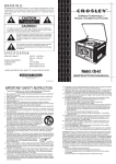
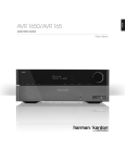
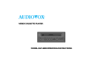
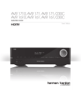
MODEL AVP-7380
Video Cassette Player
and
Built-in TV Tuner
with Voice Status Annunciator
Owner’s Instruction Manual
128-6163
1 of 24
THIS PAGE INTENTIONALLY LEFT BLANK
2
128-6163
2 of 24
Contents
Thank You ................................................................................... 3
Safety Precautions ...................................................................... 3
Cautions and Warnings ............................................................. 5
Important Safeguards ................................................................. 6
Service ........................................................................................ 7
Features ...................................................................................... 9
Front Panel Operation ............................................................... 10
Rear Panel Connections ........................................................... 11
Remote Control Operation ........................................................ 13
Getting Started ........................................................................... 15
VCP to Vehicle Connection ....................................................... 15
12 Volt Power Notes .................................................................. 15
Making VCP Connections .......................................................... 16
Basic Operation ......................................................................... 17
Specifications ............................................................................ 21
Feature List ................................................................................ 22
Bill of Material ............................................................................. 22
A. Thank You
Thank you for choosing the AVP-7380 Video Cassette Player
with built-in TV Tuner and Voice Status Annunciator. This unit is
the result of advanced technology in audio and video electronics.
Please read this manual completely before operation and retain it
for future reference.
B. Safety Instructions
1 . Read Instructions -All the safety and operating instructions
should be read before the Video Cassette Player is
operated.
2. Retain Instructions - The safety and operating instructions
should be retained for future reference.
3. Heed Cautions and Warnings -All cautions and warnings
regarding the Video Cassette Player should be adhered to.
4. Follow Instructions -All operating instructions should be
followed.
3
128-6163
3 of 24
5. Cleaning - Unplug or turn off vehicle power to the Video
Cassette Player before cleaning. Do not use liquid cleaners
or aerosol cleaners. Use only a damp cloth for cleaning.
6. Attachments - Do not use attachments not recommended
by the Video Cassette Player manufacturer as they may
cause hazards.
7. Water and Moisture - Do not use this video product near
water; for example, near a bath tub, kitchen sink, near a
swimming pool or other wet locations.
8. Accessories - Do not place the Video Cassette Player on an
unstable cart, stand, tripod, bracket, or table. The Video
Cassette Player may fall, causing serious injury to a child or
adult, and serious damage to the Video Cassette Player. Use
only with a cart, stand, tripod, bracket, or table recommended
by the manufacturer or sold with the Video Cassette Player.
When used in vehicles, the Video Cassette Player must be
securely fastened.
9. Ventilation - Slots and openings in the cabinet are
provided for ventilation to insure reliable operation of the
Video Cassette Player and to protect it from overheating.
These openings must not be blocked or covered. The
openings should never be blocked by placing the Video
Cassette Player on a bed, sofa, rug or other similar surface.
The Video Cassette Player should never be placed near or
over a radiator or heat register. This video product should
not be placed in a built-in installation such as a book case
orrack unless proper ventilation is provided.
10. Power Sources - The Video Cassette Player should be
operated only from the type of power source indicated on
the marking label. If you are not sure of the type of power
supplied to your home, consult your appliance dealer or
local power company. For video products intended to
operate from battery power of other sources, refer to the
operating instructions.
4
128-6163
4 of 24
C. Cautions and Warnings
1. Cleaning Video Head
Use only good quality VHS tapes and discard worn out
tapes to prevent video head clogging. If the heads get dirty
over a period of time during normal operation of the VCP,
the picture will be snowy and the auto-tracking will not
adjust the snow out of the picture. We recommend using
cleaning cartridges sparingly to restore normal picture.
2. Placement
To prevent fire or electric shock, do not expose this
appliance to rain, moisture, or direct sunlight, keep the unit
away from radiators or other sources of heat. Do not
operate or store the unit close to strong magnetic fields.
Do not place the set on an unstable cart, stand, tripod,
bracket or table to prevent it from falling.
3. Ventilation
Never cover or block the slots and openings in the cabinet
with a cloth or other material to ensure proper ventilation.
4. Object and Liquid Entry
Do not push objects of any kind into the set through
openings; do not spill liquid of any kind on or in the set. It
may result in a fire or electric shock. Do not place anything
heavy on the unit.
5.
Disassemble
To reduce the risk of electric shock, do not remove the
cover (or back). No user-serviceable parts inside. Refer
servicing to qualified service personnel.
5
128-6163
5 of 24
6. Cleaning Unit
Made sure unit is unplugged from power source. Do not
use liquid cleaners or aerosol cleaners. Use a cloth lightly
dampened with water for cleaning the exterior
of the set.
7. Power
This unit should be operated only from the type of power
source indicated on the marking label. Use only the
supplied power cable matching this set to avoid electric
hazards. When the unit is left unattended and unused
for long periods of time, unplug it from the power source.
Always disconnect the power source first and then the
jack from the unit.
8. Cassette
Do not force a cassette into the compartment when the
power cord is Unplugged. An inverted cassette cannot be
inserted. After playing a video cassette, remove it from
the player. Do not move the player with a cassette in the
compartment. Store videocassettes in the sleeves or cases
and position them vertically.
D. Important Safeguards
At room temperature, if you pour a
cold liquid into a glass, water vapor in
the air will condense on the surface
of the glass, This is moisture condensation. The moisture condensation
may occur inside of VCPs; if used in
this condition, it will cause damage
to the head and the tape.
6
128-6163
6 of 24
When moving the VCP from a cold place
to heated place.
Or the temperature of surroundings goes
up due to vehicle heating switched on.
Or moving the VCP suddenly from air conditioned room to a place of high
temperature or humidity in summer may
cause the dew indicator to appear on video
monitor display.
When the moisture condensation occurs
inside of the VCP, NEVER insert the
cassette into the cassette compartment.
Remove the cassette, if loaded, by
pressing the STOP/EJECT key. Only
operate the VCP after the moisture
condensation has completely dried out.
Normally, it takes about 2 hours.
SERVICE --- :
-if the set has been subjected to excessive
shock by being dropped, or the cabinet has
been damaged.
-if the set does not operate normally when
following the operating instructions, adjust
only those controls that are specified in the
operating instructions. Improper adjustment of
other controls may result in damage and will
often require extensive work by a qualified
technician to restore the set to normal
operation.
-when the set exhibits a distinct change in
performance, this indicates a need for service.
7
128-6163
7 of 24
Servicing- Do not attempt to service
the set yourself as opening or
removing covers may expose you to
dangerous voltage or other hazards.
Refer all servicing to qualified service
personnel.
Replacement of Parts - When replacement of parts is required,
be sure the service technician has used replacement parts specified by the manufacturer that have the same characteristics as the
original parts. Unauthorized substitutions may result in fire, electric
shock, or other hazards.
Safety Check - Upon completion of
any service or repairs to the set, ask
the service technician to perform
routine safety checks (as specified by
the manufacturer) to determine that the
set is in safe operating condition.
8
128-6163
8 of 24
E. Features
CONGRATULATIONS on your purchase of the Audiovox Model
AVP-7380 Video Cassette Player. This unit is designed to satisfy
all your VHS tape playback needs and with proper use and care,
will offer many years of viewing enjoyment. The features of the
Model AVP-7380 Video Cassette Player include:
• DIGITAL AUTO TRACKING
This VCP plays clear pictures without special operations.
In the Auto Tracking Mode.
• SELF PICTURE ADJUSTMENT
Since HEAD DRUM rotation continuously compensates for
voltage change or tape condition, the picture is always stable.
• AUTO START FUNCTION
This VCP will automatically power on and go into PLAY mode
when a cassette is inserted.
• 2-HEAD PLAYBACK
• AUTO REPEAT PLAYBACK
In the AUTO REPEAT mode, the VCP will , at the end of the
tape, rewind and enter the playback mode.
• INFRARED (IR) INPUT FOR REMOTE CONTROL
• DC OPERATION WITH SPECIALIZED TAPE MECHANISM
• DIAMOND-LIKE COATED (DLC) VIDEO HEAD
A special coating on the tape drum which prevents oxide and
moisture build-up.
• ILLUMINATED FUNCTION
• DEW SENSOR
BUTTONS
Prevents a tape from being played when moisture is detected
in the unit.
9
128-6163
9 5of 24
Features (Continued)
• 3 MONITOR OUTPUT PORTS
• FRONT AND REAR A/V INPUTS
• BUILT-IN 69 CHANNEL TV TUNER
• BUILT-IN VCP STATUS ANNUNCIATOR
• FULL FUNCTION REMOTE
F. Front Panel Operation
POWER Button (1)
When pressed this button alternately turns the VCP on and off.
When power is turned on, the annunciator says “Power On”; the
power indicator lights red and the other function buttons light green.
When power is turned off, the annunciator says “Power Off”.
Remote Control Sensor (2)
Infrared sensor responds to remote control inputs for VCP
operation.
AUTO REPEAT Button (3)
When this button is pressed the VCP is in the Auto Repeat Playback mode, and the button indicator lights red. At the end of the
tape, the rewind function takes over; the tape will automatically
rewind to the beginning and playback will commence again.
1.
2.
3.
4.
5.
6.
7.
8.
9.
10.
Power On/Off Button
Remote Control Sensor
Auto Repeat Button
Stop/Eject Button
Fast Rewind Button
Play Button
Fast Forward Button
Video Input Jack
Audio Left Input Jack
Audio Right Input Jack
10
128-6163
10 of 24
STOP/EJECT Button (4)
When pressed once, the annunciator says “Stop” and the tape is
stopped. When pressed again the tape is ejected.
REW/Review Button (5)
If this button is pressed in the PLAYBACK mode, the VCP enters
the reverse picture search mode. If pressed in STOP mode, the
annunciator says “Rewind” and the tape will rewind at high speed.
PLAY Button (6)
Press this key to play back a recorded tape. In the playback mode,
the annunciator says “Play” and the playback indicator lights.
F FWD/Cue Button (7)
When this button is pressed during playback, the VCP enters the
forward picture search mode. When pressed during stop, the
annunciator says “Fast Forward” and the tape will fast forward at
high speed.
VIDEO IN Jack (8)
Connect this jack to the video out jack/terminal of your Game
machine, Camcorder, or Portable DVD Player.
AUDIO IN L Jack (9)
Connect this jack to the left audio out jack/terminal of your Game
machine, Camcorder, or Portable DVD Player.
AUDIO IN R Jack (10)
Connect this jack to the right audio out jack/terminal of your Game
machine, Camcorder, or Portable DVD Player.
11
128-6163
11 of 24
G. Rear Panel Connections
DC 12V INPUT Jack (1)
When using a DC power source, connect this jack to 12 Vdc TV
ANT. Connector (2)
Connect the TV antenna to this connector.
MONITOR PORT 1 Connector (3)
Connects to external Monitor for remote viewing purposes.
MONITOR PORT 2 Connector (4)
Connects to external monitor for remote viewing purposes.
MONITOR PORT 3 Connector (5)
Connects to external monitor for remote viewing purposes.
VIDEO INPUT Jack (6)
Connect this jack to the video out jack/terminal of your Game
machine, Camcorder, or Portable DVD Player.
AUDIO INPUT L Jack (7)
Connect this jack to the left audio out jack/terminal of your Game
machine, Camcorder, or Portable DVD Player.
AUDIO INPUT R Jack (8)
Connect this jack to the left audio out jack/terminal of your Game
machine, Camcorder, or Portable DVD Player.
SPEAKER OUTPUT Jack (9)
Connect the external speaker to this jack for voice annunciator.
REMIR Jack (10)
This connector provides the interface with the IR input of the
Remote Control.
12
128-6163
12 of 24
EXTERNAL SPEAKER
1. Voice High/Low/Off Switch
2. Plug of Speaker
H. Remote Control Operation
TV/VIDEO Button (1)
Pressing this button selects from TV (external antenna
connected to the Antenna jack), VIDEO 1 (internal VCP) or VIDEO
2 (front or rear A/V inputs).
NOTE: Plugging into the front panel A/V inputs overides all other
inputs.
Keypad Buttons (2)
These buttons provide direct access to TV channels. The channel
number chosen will be displayed on the screen for 4 seconds.
1. TV/VIDEO Key
2. Number Keys
3. Skip Search Key
4. Erase Write Key
5. Channel Up Key
6. Channel Down Key
7. Auto Memory Key
8. Main Power Key
9. Rewind Key
10. FastForward Key
11. Play Key
12. Stop Key
SKIP/SEARCH Button (3)
Pressing this button toggles between skip mode on and skip
mode off. With skip mode on, only the channels programmed in
memory are accessed with the channel up/down buttons; with
skip mode off, all channels can be accessed with the channel
up/down buttons.
13
128-6163
13 of 24
ERASE/WRITE Button (4)
This button is used to add or erase channels from memory. To
erase a channel, use the keypad buttons to select the desired
channel and press the ERASE/WRITE button; ERASED will
appear on the screen. To add a channel to memory, use the
keypad buttons to select the desired channel and press the
ERASE/WRITE button; ADD will appear on the screen.
Channel Up ( CH ) Button (5)
Pressing this button with skip mode off will access all channels
in the up direction; with skip mode on, only those channels
stored in memory can be accessed.
Channel Down (
CH ) Button (6)
Pressing this button with skip mode off will access all channels
in the down direction; with skip mode on, only those channels
stored in memory can be accessed.
AUTO MEMORY Button (7)
When this button is pressed, the tuner will scan all strong
broadcast signals and store them in memory.
MAIN POWER Button (8)
When pressed, this button alternately turns the AVP-7380 on
and off; the annunciator says “Power On” or “Power Off”.
REW Button (9)
If this button is pressed in the PLAYBACK mode, the VCP enters
the reverse picture search mode. If pressed in STOP mode, the
annunciator says “Rewind” and the tape will rewind at high speed.
F FWD Button (10)
When this button is pressed during playback, the VCP enters
the forward picture search mode. When pressed in stop mode,
the annunciator says “Fast Forward” and the tape will fast
forward at high speed.
14
128-6163
14 of 24
PLAY Button (11)
Press this key to play back a recorded tape. In the playback mode,
the annunciator says “Play” and the playback indicator lights.
STOP Button (12)
When pressed once, the annunciator says “Stop” and the tape is
stopped. When pressed again the tape is ejected.
I. Getting Started
VCP TO VEHICLE CONNECTION
• Connect the unit to a 12 Vdc source only.
• The unit should be connected to the vehicle only after
verifying the polarity of the Power Source (12 Vdc with
negative ground).
12 VOLT POWER NOTES
• This VCP operates on 12 Vdc only. If you apply more than
18 Vdc, the VCP will automatically turnoff.
15
128-6163
15 of 24
• If the polarity is reversed, the unit will not operate.
• Use of this VCP is not recommended in excessive heat. If
the inside temperature of the vehicle is over 100 F, do not use
the VCP. Allow the VCP to cool before use.
MAKING VCP CONNECTIONS
1. Powering the Unit:
Insert one end of the power connector into the 4 PIN DC
12V jack on the back of the unit; connect the other end to
an ACC (switched) power source of the vehicle.
2. Connecting the Antenna:
Connect the coaxial cable of the external antenna to the TV
ANT jack on the back of the unit.
3. Driving the External Monitors:
Connect any of the 3 MONITOR PORTS in the rear of the
unit to the external monitor to output DC 12V power, audio,
video and IR input signals all in one DIN jack to the external
monitor. Depending on the connector type of the monitor,
you can use the supplied DIN convertor cable, or the DIN
cable that we may supply as the optional accessory.
4. A/V Inputs:
a.Plug the video output from an auxiliary source such as
Game and Camcorder into the yellow video jack,
and the audio L and audio R into the appropriate jacks in
the front of the unit.
NOTE: Plugging into the front panel A/V inputs overides
all other inputs. (TV, VCP, Rear Aux input)
b. Plug the video output from an auxiliary source such as
DVD Player, VCP, VCR and so on into yellow video jack,
and the audio L and audio R into the appropriate jacks in
the rear of the unit.
5. External Speaker:
Input the plug of the separate Speaker into the
SPEAKEROUTPUT JACK for transmitting the sound from
16
128-6163
16 of 24
the built-in voice annunciator to the Speaker. Use the LOW/
MED/HI switch to adjust the volume.
6. Control the Unit Remotely:
Plug REMIR into this jack and extend the sensor of the REMIR
to where the driver can control the unit conveniently with the
Remote Control pointing to the sensor.
7. Secure the VCP to the vehicle using the supplied mounting
brackets to ensure safe operation.
J. Basic Operation
1. POWER
Plug in the unit, and the power lamp will turn on. Press the
POWER key to switch on or off the power. The lamp will be
brighter when the unit is on.
2. TV/VIDEO
Press the TV/VIDEO key on the remote control to select the
tuner (TV) mode, the VCP mode (VIDEO 1) and the rear AV
INPUT mode (VIDEO 2) in turn. When the power turns on,
the unit goes to the mode with last memory.
NOTE: Plugging the front-mounted AV inputs overides all
other inputs.
3. CASSETTE LOADING/UNLOADING
a. Loading the Cassette:
1) Gently push the cassette into the cassette
compartment, making sure the cassette arrow is on
top.
NOTE:The cassette cannot be inserted upside
down.
2) If VCP power is off when the cassette is inserted,
power will turn on as long as the VCP is connected
to the power source, and the cassette will begin to
play.
17
128-6163
17 of 24
b. Unloading the Cassette:
If the VCP is in the playback mode, press the STOP/
EJECT button twice; the first press will stop tape play,
and the second press will eject the tape.
NOTE:
The cassette will be ejected even if VCP power
is off, as long as the unit is connected to the
power source.
4. AUTO MEMORY
Press the AUTO MEMORY key for searching and storing
automatically the TV channels with on-screen display,
the unit will start to play the first channel automatically.
5. SKIP SEARCH
a. Press the SKIP SEARCH key until SKIP MODE ON is
displayed on the screen. Then if using the channel up
and down keys, the TV will stop only on the active TV
channels.
b. Press the SKIP SEARCH key until SKIP MODE OFF is
displayed on the screen. Then all the TV channels will
be shown using the channel up and down keys.
6. CHANNEL UP/DOWN
Press the CHANNEL UP and DOWN keys to get your
desired TV channel.
7. DIRECT ACCESS
Press the number keys to make a direct TV channel
selection. The channel number chosen will be displayed on
the screen for about 4 seconds.
18
128-6163
18 of 24
8. ERASE/WRITE
To erase a TV channel, press the ERASE/WRITE key until
MANUAL MEMORY has “erase” displayed on the screen. To
store a TV channel, press this key until MANUAL MEMORY
has “add” displayed on the screen.
9. VCP AUTO START
After plugging the DC power cord, push the cassette into the
cassette compartment gently, the VCP automatically
powers on if it was off, and goes into the play mode. Select
VIDEO 1.
10. STOP/EJECT
Press the STOP/EJECT key to stop tape; the voice
annunciator will say “STOP”. Press this key once
more to eject tape.
11. HIGH/LOW/OFF
Push the HI/LO/OFF switch to select high volume, low
volume, or volume off for the Voice Status Annunciator
Speaker. (Located on external speaker).
12. REWIND/SCAN
a. Press the REWIND key once in the playback mode, and
the VCP enters the reverse picture search mode and
the tape will rewind rapidly with picture. The rewind
indicator lamp will blink. Press this key once more, the
tape will rewind/scan at a high speed with the lamp
blinking more quickly.
19
128-6163
19 of 24
b. Press the REWIND key in the stop mode, the voice annunciator will say “REWIND” , and the tape will
rewind at a very high speed without any picture or
sound. The rewind indicator lamp will blink very quickly.
13. PLAYBACK
Press the PLAYBACK key in the stop mode to playback a
tape, and the voice annunciator will say “PLAY”. You can
also press this key to release special operations such
as the search mode.
14. FAST FORWARD/SCAN
a. Press the FAST FORWARD key once in the playback
mode; the VCP enters the forward picture search mode
and the tape advances rapidly with picture. The
fast forward indicator lamp will blink. Press this key
once more; the tape will forward/scan at a high speed
with the lamp blinking more quickly.
b. Press the FAST FORWARD key in the stop mode, the
voice annunciator will say “FAST FORWARD”, and the
tape will advances at a very high speed without any
picture or sound. The fast forward indicator lamp will
blink very quickly.
15. AUTO REPEAT
When this button is pressed the VCP is in the Auto Repeat
Playback mode, and the button indicator lights red. At the
end of the tape, the rewind function takes over; the tape will
automatically rewind to the beginning and playback will commence again.
20
128-6163
20 of 24
K. Specifications
System
Remote Control
Antenna
Channels
NTSC
Infrared
External Antenna Jack
2-6 (VHF low), 7-13 (VHF high),
14-69 (UHF)
1 track
12.7mm
33.35mm/s
180 minutes with T-180 set to
Audio track
Tape width
Tape speed SP
Playback time
SP mode
FF/REW time
Heads
Video Output
Video signal-to noise ratio
Audio output
Audio signal-to–noise ratio SP
Frequency response SP
Power Supply
Power Consumption
Operating Humidity
Operating Temperature
Storage Temperature
Less than 7 minutes with
T-120
2 helical scanning system
1.0 Vp/p, 75ohm, unbalanced
Better than 40 dB
1W
Better than 40 dB
100 Hz-7kHz
DC 12V
30W
10~75%
41~104 degrees Fahrenheit
(5~40) centigrade
4~140 degrees Fahrenheit
(-20~60) centigrade
10.9” x 3.8” x 9.8”
7 pounds 6 ounces
Dimensions (W x H x D)
Weight
21
128-6163
21 of 24
L. Bill of Material
* 1 x VCP with built-in TV Tuner & Voice Status Annunciator
* 1 x Speaker
* 1 x Remote Control
* 1 x REMIR
* 1 x DIN Convertor Cable
* 1 x DC Power Connector
* 2 x Brackets with 4 x Screws
* 1 x Owner’s Manual
22
128-6163
22 of 24
36 MONTH LIMITED WARRANTY
Applies to Audiovox Mobile Video Products
AUDIOVOX ELECTRONICS CORP. (the Company) warrants to the original retail
purchaser of this product that should this product or any part thereof, under
normal use and conditions, be proven defective in material or workmanship
within 36 months from the date of original purchase, such defect(s) will be
repaired or replaced with reconditioned product (at the Company's option)
without charge for parts and repair labor.
To obtain repair or replacement within the terms of this Warranty, the product
is to be delivered with proof of warranty coverage (e.g. dated bill of sale),
specification of defect(s), transportation prepaid, to the Company at the
address shown below.
This Warranty does not extend to the elimination of externally generated static
or noise, to correction of antenna problems, to costs incurred for installation,
removal or reinstallation of the product, or to damage to tapes, discs, speakers,
accessories, or vehicle electrical systems.
This Warranty does not apply to any product or part thereof which, in the
opinion of the Company, has suffered or been damaged through alteration,
improper installation, mishandling, misuse, neglect, accident, or by removal or
defacement of the factory serial number/bar code label(s). THE EXTENT OF
THE COMPANY'S LIABILITY UNDER THIS WARRANTY IS LIMITED TO THE
REPAIR OR REPLACEMENT PROVIDED ABOVE AND, IN NO EVENT, SHALL THE
COMPANY'S LIABILITY EXCEED THE PURCHASE PRICE PAID BY PURCHASER
FOR THE PRODUCT.
This Warranty is in lieu of all other express warranties or liabilities. ANY IMPLIED
WARRANTIES, INCLUDING ANY IMPLIED WARRANTY OF MERCHANTABILITY, SHALL BE LIMITED TO THE DURATION OF THIS WRITTEN WARRANTY.
ANY ACTION FOR BREACH OF ANY WARRANTY HEREUNDER INCLUDING
ANY IMPLIED WARRANTY OF MERCHANTABILITY MUST BE BROUGHT
WITHIN A PERIOD OF 48 MONTHS FROM DATE OF ORIGINAL PURCHASE. IN
NO CASE SHALL THE COMPANY BE LIABLE FOR ANY CONSEQUENTIAL OR
INCIDENTAL DAMAGES FOR BREACH OF THIS OR ANY OTHER WARRANTY,
EXPRESS OR IMPLIED, WHATSOEVER. No person or representative is
authorized to assume for the Company any liability other than expressed herein
in connection with the sale of this product.
Some states do not allow limitations on how long an implied warranty lasts or
the exclusion or limitation of incidental or consequential damage so the above
limitations or exclusions may not apply to you. This Warranty gives you specific
legal rights and you may also have other rights which vary from state to state.
U.S.A. :
AUDIOVOX ELECTRONICS CORPORATION, 150 MARCUS BLVD.,
HAUPPAUGE, NEW YORK 11788 1-800-645-4994
CANADA : CALL 1-800-645-4994 FOR LOCATION OF WARRANTY STATION
SERVING YOUR AREA
128-5148C
23
128-6163
23 of 24
© 2001 Audiovox Electronics Corp., Hauppauge, NY 11788
Printed in Korea
128-6163
24
128-6163
24 of 24